
Abstract
This paper proposes an attitude control scheme for the Dove flapping wing micro air vehicle in intermittent flapping and gliding flight. The Dove flapping wing micro air vehicle adopts intermittent flapping and gliding flight to make the wing movements more natural; this strategy also has the potential to reduce energy consumption. To implement this specific flight mode, this paper proposes a closed-loop active disturbance rejection control strategy to stabilize the attitude during the processes of flapping flight, transition and gliding flight. The active disturbance rejection control controller is composed of three parts: a tracking differentiator, a linear extended state observer and a nonlinear state error feedback controller. The tracking differentiator estimates the given target signal and the differential signal in real time. The extended state observer estimates the system states and system nonlinearity. Moreover, the bandwidth parameterization method is applied to determine the observer gains. The stability of the closed-loop system is verified using Lyapunov’s theorem. Several outdoor flight experiments have been conducted to verify the effectiveness of the proposed control method, and the results show that the proposed method can guarantee the stability of intermittent flapping and gliding flight.
Keywords
Introduction
Inspired by the unmatched flying capabilities of birds in nature, researchers have developed many types of bird-like flapping wing air vehicles,1–4 The Dove flapping wing micro air vehicle (FWMAV) is one of them. 4 Similar to large- and medium-sized birds, the Dove FWMAV often flies via a process consisting of low-frequency flapping flight, transition and gliding flight due to the high mass and large inertial force of the flapping wings. This combined flight mode integrating low-frequency flapping flight and gliding flight is often called the intermittent flapping and gliding flight mode.5,6 A simplified profile of this flight mode is shown in Figure 1. The most significant advantages of intermittent flapping and gliding flight are the resultant increases in flight range and endurance. 7 However, this flight mode poses difficulties in control system design, especially in control of transitions between flapping and gliding.
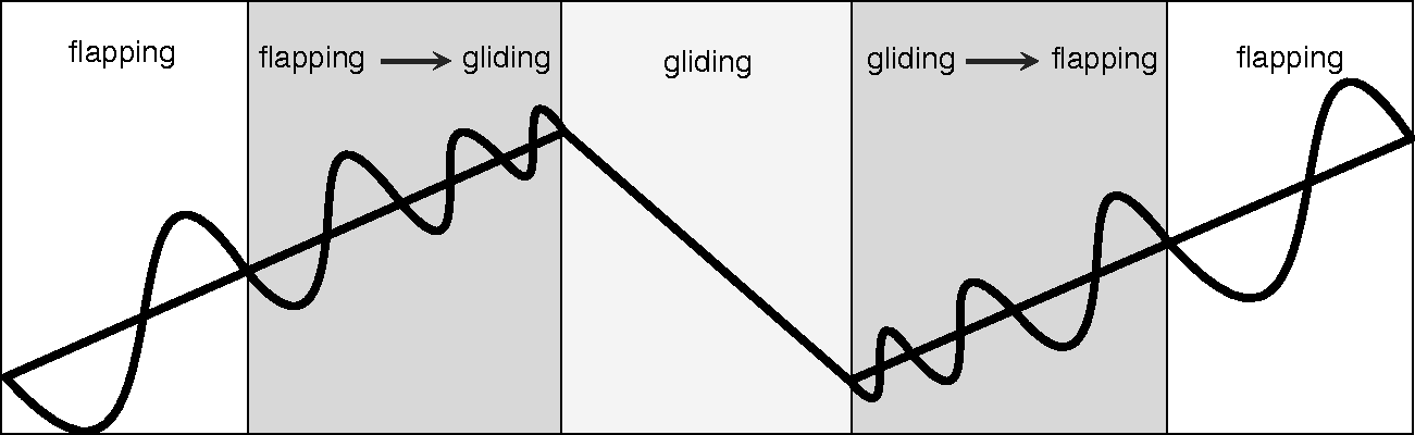
A simplified profile of the intermittent flapping and gliding flight mode.
First, the dynamic characteristics of the system exhibit large variations during the transitions between the two flight modes. In the flapping flight mode, the aerodynamic force and torque vary periodically, and the characteristics are strongly nonlinear. 8 By contrast, in the gliding flight mode, the aerodynamic force and torque vary linearly within certain ranges. 9
Second, a precise aerodynamic model of the transition process between the two flight modes is difficult to establish. The flapping frequency and flapping amplitude are time varying in the transition process. Moreover, the three-dimensional form of the flapping motion is complicated, and the flapping wings experience flexible deformations. Therefore, it is difficult to obtain a precise aerodynamic model. Although some approximation methods for aerodynamic force calculations have been proposed by researchers, such as the quasi-steady model,10,11 the thrust calculation accuracy is still not high.
Furthermore, FWMAVs are inevitably affected by unknown external disturbances in flight, such as wind disturbances and electromagnetic interference, which further complicates the control system design.
So far, significant progress has been made in flight control of FWMAVs in both low-frequency flapping flight and gliding flights.12–19 For low-frequency flapping mode, Baek et al. 14 designed a closed-loop attitude control system using the proportional-integral-derivative (PID) control technique. Without the help of external measurement instruments, the system gives an ornithopter the ability to fly towards a target using only onboard sensing and computation. Roberts et al. 15 modeled the diving behavior of a real FWMAV. They employed lookup tables with metamodels to control dive maneuver that is demonstrated on the Robo Raven FWMAV platform. Autonomous dives were executed successfully and reached within 6 m of the goal location, which is very close to the model error. Dietl et al. 16 tested and compared the control effects of several different controllers. The results of flight simulations showed that periodic time-varying controllers can effectively decrease tracking errors. He et al. 17 constructed a full-state feedback controller. With measurement results from a Vicon composite motion capture system, the altitude control of the FWAMV was satisfactory. Because the flapping wings are fixed in a particular position in the gliding flight mode, FWMAVs operating in this mode have the same flight pattern as fixed-wing aircraft. As a result, the common control methods applied for the gliding flight of fixed-wing aircraft, such as adaptive control methods 18 and robust control methods, 19 can also be used for the gliding flight of FWMAVs with only slight changes. Notably, the above control system design methodologies mostly solve only the control problem associated with a single flight mode. Very few works address the control problem for the transition process between flapping and gliding flight.
The characteristics of the aerodynamic forces exhibit large variations during the transformations between the flapping and gliding modes, and the efficiency of the control surface gradually decreases with decreasing flight speed. Consequently, the control effect of the traditional PID method deteriorates, potentially even causing flight accidents. To ensure stable control during the transition process and while considering the needs of both the flapping and gliding processes, this paper presents an active disturbance rejection control (ADRC) method to address the problems encountered in intermittent flapping and gliding flight. This control strategy is independent of a precise mathematical model and has a strong anti-interference ability.20–22 It is able to estimate the total disturbance of the system, including changes in the system dynamics. The controller presented in this paper is composed of three parts: a tracking differentiator, a linear extended state observer (ESO) and a nonlinear state error feedback controller. The function of the tracking differentiator is to smooth the target signal and obtain the corresponding differential value. This approach can reduce system overshoot and response time. 23 Therefore, the tracking differentiator can protect the actuator of an FWMAV from being damaged. The ESO is less dependent on an accurate model and takes the system nonlinearity as the extended state to be estimated. This observer has high efficiency in estimating nonlinear dynamics. 24 Hence, it is appropriate for intermittent flapping and gliding flight. The nonlinear state error feedback controller is constructed with nonsmooth functions. Thus, small errors lead to high gains, and large errors lead to small gains.25,26 This feature guarantees effective control during intermittent flapping and gliding flight. Under the synergistic effects of these three system components, an ADRC controller is developed to overcome the problems related to large variations in the system dynamics, imprecise mathematical models and unknown external disturbances.
Compared with other works, the main contributions of this paper are as follows.
An ADRC strategy is applied to control the attitude of the Dove FWMAV during intermittent flapping and gliding flight, which involves a nonlinear time-varying system. Outdoor flight tests reveal good control effects with the proposed controller. The convergence of the ESO is demonstrated. The stability of the closed-loop system is proven by using the Lyapunov stability theorem.
The remainder of this paper is organized as follows. The Dove FWMAV with flapping and gliding flight capabilities is introduced in the Dove FWMAV section. The dynamic model of the FWMAV system and the problem formulations are given in the Dynamic model of the Dove FWMAV section. An attitude controller design strategy and a stability analysis of the closed-loop system based on a Lyapunov function are presented in the Control design section. Then, several outdoor flapping and gliding intermittent flight experiments are conducted to verify the effectiveness of the attitude controller we proposed. The experimental results are presented in the Experimental results and analysis section, and concluding remarks are given in the Conclusion section.
Dove FWMAV
The Dove FWMAV considered in this paper is shown in Figure 2. The geometric parameters of the wing and fuselage are similar to those of adult pigeons. The planar dimensions of a single flapping wing are shown in Figure 3. The basic parameters of the flying platform are listed in Table 1. The lift force and thrust needed for flight are generated by a pair of flapping wings. The driving mechanism of the Dove FWMAV is shown in Figure 4. The design of this mechanism is based on the four-bar principle. When the Dove is operating in the gliding flight mode, the four-bar mechanism is simply held in the dead point position to ensure that the position of the flapping wings is fixed. The actuators of the Dove FWMAV are shown in Figure 5. The tailerons are driven by two steering gears. A pitch control torque is generated by deflecting the control surfaces in the same direction. A roll control torque is generated by deflecting the control surfaces in opposite directions. This bird-like FWMAV has high structural efficiency 27 and the ability to perform both flapping flight and gliding flight. 28 Hence, this paper takes the Dove as the control object to study the problem of attitude control in intermittent flapping and gliding flight.

Photograph of the Dove FWMAV.
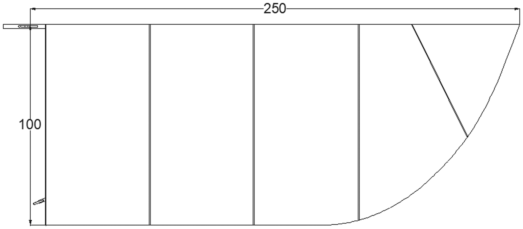
The planar dimensions of a single flapping wing.
Basic parameters of the Dove FWMAV.

FWMAV: Flapping wing micro air vehicle.

Driving mechanism of the Dove FWMAV.

Actuators of the Dove FWMAV.
The origin of the body-axis coordinate system is located at the centre of mass. The attitude of the aircraft is represented by the roll, pitch, and yaw angles.
Dynamic model of the Dove FWMAV
Based on rigid body dynamics theory, the following equations of angular motion from Liu
29
are adopted to describe the motion characteristics during intermittent flapping and gliding flight

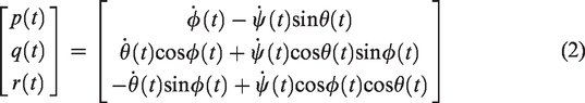
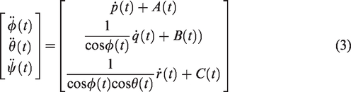


As the flapping frequency and amplitude decrease, the changes in the three axial torques,
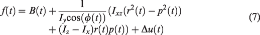
For simplicity, we take pitch control as an example in this paper. The other two control channels can be analyzed using the same method. The dynamics equation for the pitch channel can be expressed as follows


Control design
In consideration of the complicated nonlinear characteristics of the studied FWMAV during intermittent flapping and gliding flight, an ADRC strategy is designed to stably and accurately achieve attitude control. The block diagram of the ADRC is shown in Figure 6.
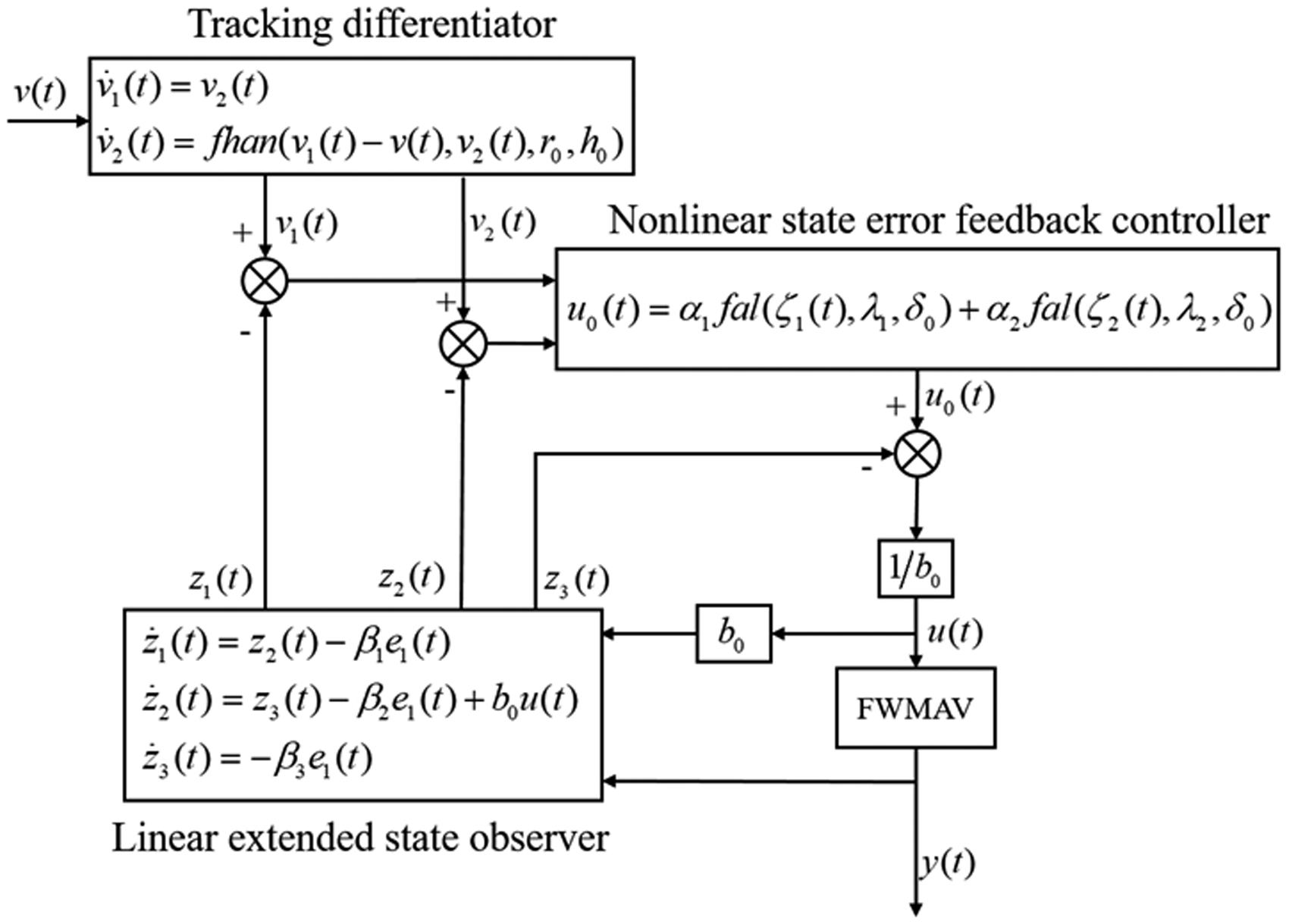
The block diagram of the ADRC controller.
In Figure 6, the function of the tracking differentiator is to smooth the input signal
Tracking differentiator design
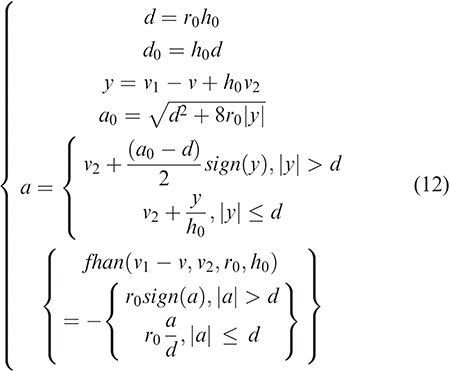
Since the input signal is occasionally abrupt, the differential signal is fairly large in magnitude. If the corresponding control law is designed by utilizing the large differential signal, system overshoot can easily occur. To avoid this problem, a transient process must be constructed. Note that the selection of a nonlinear function in the design of the tracking differentiator is not invariable. However, the most widely used form for tracking differentiators was proposed in Han,
20
and this form has been proven to be correct and effective in various practical systems. On the basis of the form presented in Han,
20
the tracking differentiator proposed in this paper is designed to obtain the continuous and smooth differential signal for the actual target signal in this paper. The tracking differentiator is designed as follows

Linear ESO design
To simplify the parameter adjustment process and controller structure for practical engineering applications, a linear ESO is introduced to address uncertain disturbances and the unknown nonlinear dynamics of the FWMAV system, as described in equation (10). For simplicity, the strongly nonlinear term 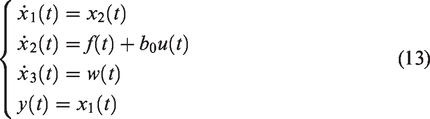


We assume that
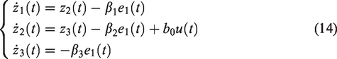
Notably, the constructed linear ESO (equation (14)) is able to observe the total disturbance, i.e.
Nonlinear state error feedback controller design
The different feedback forms of the system state variables significantly differ in restraining uncertain disturbances. The superiority of a nonlinear feedback form in this respect is obvious. The errors between the tracking differentiator and the linear ESO are given as follows


For simplicity, 
Then, the error equation (17) can be written in the following form

Based on the above analysis, from equations (11), (17) and (20), we propose the following error system

Note that Consider the closed-loop system (equation (22)) with the nonlinear state error feedback controller (equation (18)). If the controller gains A Lyapunov function is constructed as follows

where
According to equations (18), (21) and (23), the derivative of 

According to the analysis above, we conclude that
Letting 
That is, an appropriate coefficient
According to the analysis above, we conclude that if the coefficients
Experimental results and analysis
The flight test platform consisted of a Dove FWMAV, an autopilot, a ground control station, and a remote-control unit. An elevator was installed on the horizontal stabilizer to achieve attitude control. The microcontroller was a PX4 open-source autopilot running on Pixfalcon hardware. The QGroundControl software was used for control instruction generation and flight data surveillance. The flight target signal was generated by the autopilot. To verify the effectiveness and practicability of the proposed control method, we conducted several outdoor flight tests, including flapping flight tests, gliding flight tests and intermittent flapping and gliding flight tests. The experimental results presented here are based on real flight data. During testing, the data recording and the operation of the control algorithm were all performed online. Real flight data were recorded on the onboard memory card. In each of the three types of tests, the ADRC controller had the same controller gains. Moreover, the test results were analysed and compared with those of the proportional-derivative control method, which is one of the most universally used methods in aircraft attitude control applications. The controller structure of the proportional-derivative method is as follows:
Basic parameters of the ADRC controller.

ADRC: Active disturbance rejection control.
Experimental results in the flapping flight mode
The target signal designed for the flapping flight tests is as follows

It is a sinusoidal signal. The coefficients in the formula were determined based on the flight capability of the aircraft. The throttle signal was in the full position, that is,

Experimental results for tracking a sinusoidal signal with an amplitude of 4.5° and a frequency of 0.2 Hz using the proposed ADRC controller.

Experimental results for tracking a sinusoidal signal with an amplitude of 4.5° and a frequency of 0.2 Hz using the proportional-derivative controller.
The flapping frequency was measured to be approximately 10 Hz in the flapping flight tests. Because of the influence of the wing motion, the pitch angle is characterized by periodic fluctuations within a small range. The pitch data is generally going to show up as a “double peak” in flapping flight. The reason for this behaviour is that there is a non-zero thrust component in addition to the lift that affects the attitude of the FWMAV. As shown in Figure 7, although the pitch angle fluctuates periodically, the overall trend tracks the target signal “PitchSP” with a small phase delay. Moreover, the observed value
Experimental results in the gliding flight mode
The target signal designed for the gliding flight tests is as follows

It is a step signal. The coefficients in the formula were selected according to the actual variation range of the pitch angle. The throttle signal was in the zero position, that is,

Experimental results for tracking a step signal at 6.75° using the ADRC controller.

Experimental results for tracking a step signal at 6.75° using the proportional-derivative controller.
The efficiency of the control surface gradually decreases over time in the gliding flight mode. 32 If the airspeed is too low, a flight stall may occur, which is a threat to flight safety. Therefore, the duration of gliding flight should not be too long, which requires a fast response time of the controller. In this study, the gliding time was designed to be 2.5 s. As shown in Figure 9, the pitch output can be controlled to track a step signal at 6.75° based on the ADRC method. The tracking differentiator constructs a transient process and smoothens the target signal. The time delay is approximately 1 s. The control results of the proportional-derivative controller are shown in Figure 10. As seen from the trend of the curves, as time continues to elapse, the pitch angle output may eventually be able to track the target signal. However, it is difficult to track the signal within 2.5 s. As shown in this figure, compared with the control results of the ADRC method, the proportional-derivative controller has a longer time delay and a larger tracking error.
Experimental results in the intermittent flapping and gliding flight mode
Birds in nature can dynamically adjust their intermittent flapping and gliding flight strategy in accordance with their flight states and the external environment. The energy costs are closely related to specific flight strategies. 33 To verify the effect of the proposed controller, a fixed flight strategy was adopted in this study. A flow chart of the flight process during the intermittent flight tests is shown in Figure 11. Before each test, to ensure flight safety, it was necessary to check whether the altitude and attitude were in the appropriate ranges.

Flow chart of the flight process during the intermittent flight tests.
For the intermittent flapping and gliding flight tests, the target signal was designed as follows
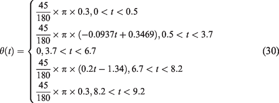
To achieve safe intermittent flapping and gliding flight, the throttle signal was designed as follows

During intermittent flapping and gliding flight, the throttle signal was controlled based on formula (31). The result was that the flapping frequency decreased to zero in the transition mode. Snapshot images of the flapping mode and the gliding mode are shown in Figure 12. The tracking effect of the ADRC controller is shown in Figures 13 through 15.
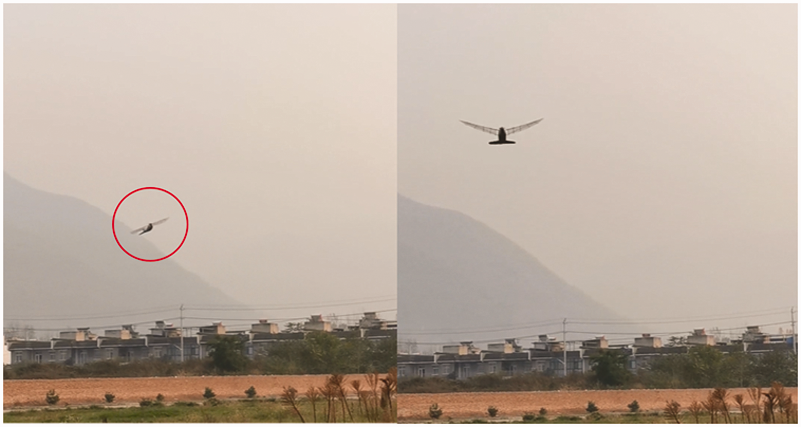
Snapshot images of the flapping mode (left) and the gliding mode (right).
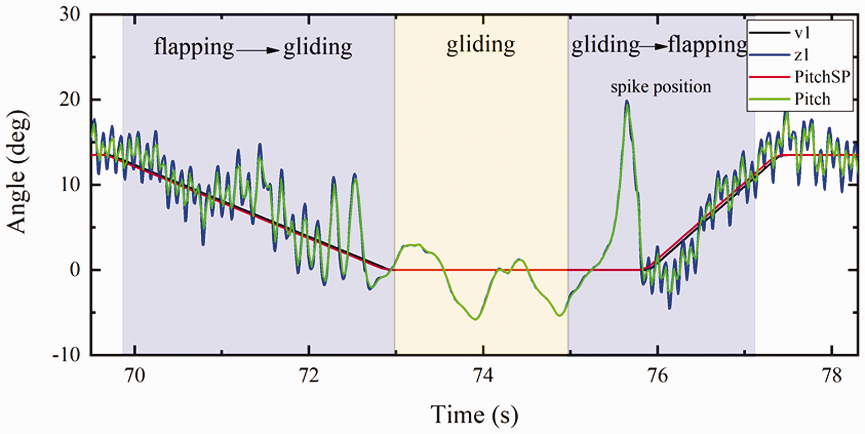
Experimental results for pitch angle tracking control during intermittent flapping and gliding flight using the ADRC controller.
Figure 13 shows the pitch angle fluctuations over time during intermittent flapping and gliding flight. As shown in Figure 13, the pitch angle fluctuates periodically around the target angle during the transition process from flapping flight to gliding flight. The tracking performance is good. In the gliding flight mode, the decrease in the control efficiency results in a poor control effect. The error between the peak pitch angle and the target angle is approximately 6°. During the transition from gliding flight to flapping flight, the start of flapping motion results in an abnormal spike in the pitch angle. After this spike, the pitch angle begins to track the target angle again. Throughout the whole transition process, the output value

Experimental results for the observed pitch angle rate during intermittent flapping and gliding flight using the ADRC controller.

Experimental results for the control input and the observed system nonlinearity during intermittent flapping and gliding flight using the ADRC controller.
To further explain the characteristics of the ADRC strategy, the control effects of the proportional-derivative control method are compared. Figure 16 shows the corresponding experimental results. As shown in Figure 16, complete intermittent flapping and gliding flight can be achieved by the proportional-derivative controller. However, compared with the experimental results based on the ADRC method shown in Figure 13, the tracking error of the proportional-derivative controller is larger during flapping flight. The error between the peak pitch angle and the target angle is approximately 11° during gliding flight, which is greater than the 6° error of the ADRC controller. At the spike position, because the system nonlinearity is not estimated and compensated, the proportional-derivative controller can track the target signal only after two oscillations.

Experimental results for pitch angle tracking control during intermittent flapping and gliding flight using a proportional-derivative controller.
The reason for the above phenomenon is as follows. During intermittent flapping and gliding flight, the system nonlinearity exhibits large variations. The ADRC method performs real-time nonlinear estimation and compensation; therefore, it is a more appropriate method to be used in intermittent flapping and gliding flight.
Because of the complexity of the outdoor flight environment, the initial values of the system and the external disturbances could not be identical in each test. Therefore, the above analysis is only a qualitative analysis of the experimental results. However, the findings sufficiently indicate that the proposed ADRC method provides effective control during intermittent flapping and gliding flight.
Conclusion
To address the problems related to large variations in system dynamics, imprecise mathematical models and unknown external disturbances in intermittent flapping and gliding flight, an ADRC controller is successfully designed for the attitude stabilization of the Dove FWMAV operating in this intermittent flight mode. The results of outdoor flight experiments show that the controller proposed in this paper can achieve satisfactory control effects in terms of tracking precision and phase delay. Moreover, due to its real-time compensation capability, the controller can effectively counteract the adverse effects caused by the start of flapping motion and has good prospects for engineering applications.
Although the controller constructed in this paper is based on the Dove FWMAV, it can also be used in other bird-like FWMAVs with flapping and gliding flight capabilities. In the experiment section, the target motions introduced in this paper were revised repeatedly according to the flight data and flight experience. In general, different target trajectories will result in different levels of energy consumption. Therefore, there may be better target trajectories. In the future, we will optimize the flapping and gliding strategy to reduce the flight energy consumption.
Footnotes
Declaration of conflicting interests
The author(s) declared no potential conflicts of interest with respect to the research, authorship, and/or publication of this article.
Funding
The author(s) disclosed receipt of the following financial support for the research, authorship, and/or publication of this article: This study was supported by the National Key Research and Development Program of China (Grant No. 2017YFB1300102) and the National Natural Science Foundation of China (Grants Nos 11872314 and U1613227).