
Abstract
This study investigates the wing deformation of the DelFly II in forward flight conditions. A measurement setup was developed that maintains adequate viewing axes of the flapping wings for all pitch angles. Recordings of a high-speed camera pair were processed using a point tracking algorithm, allowing 136 points per wing to be measured simultaneously with an estimated accuracy of 0.25 mm. The measurements of forward flight show little change in the typical clap-and-peel motion, suggesting similar effectiveness in all cases. It was found that an air-buffer remains at all times during this phase. The wing rotation and camber reduction during the upstroke suggests low loading during the upstroke in fast forward flight. In slow cases a torsional wave and recoil is found. A study of the isolated effects showed asymmetric deformations even in symmetric freestream conditions. Furthermore, it shows a dominant role of the flapping frequency on the clap-and-peel, while the freestream velocity reduces wing loading outside this phase.
Keywords
Introduction
Aerodynamic efficiency of flapping-wing fliers was poorly understood until the later part of the 20th century. The low Reynolds number regime in which insects fly should not allow for sufficient lift production to fly. Nonetheless, relatively high lift coefficients are found for hovering insects. 1 Reason for this was later found to be the occurence of strong leading edge vortices (LEVs), which remain attached to the wing surfaces and delay stall. Especially the “clap-and-fling” mechanism was found to harness this effect strongly, 2 where LEVs are created between two separating wings.
The wings were thereby assumed to separate rigidly, without any deformation. Subsequent studies however showed that insect wings are highly flexible, 3 which further increases efficiency due to passive deformations of the wing shape such as dynamic camber production and wing twisting. 4 Camber production is thereby assumed to be especially influential, as it delays the LEV detachments, which improves the delayed stall effect. 5
The present effects occur due to the interaction of aerodynamic and structural, i.e. inertial and elastic, forces and must therefore be considered in all discussions. Inertial forces acting on the wing trailing edge were, for instance found to result in a phase lag, 3 which initiates a recoil effect after stroke reversal that is beneficial to thrust production. 6 Elastic forces built up over the stroke can lead to extended rotation of the wing trailing edge at the stroke end, while aerodynamic forces act as damping. 7
In this study, the specific interaction of the flapping-wing micro air vehicle (MAV) “DelFly II,” 8 henceforth simply called “DelFly,” is investigated. This MAV features two wing pairs in an X-wing configuration, which “clap-and-peel” 5 on each side. Several studies of the force production 9 and flow field around the DelFly have already been carried out10–12; however, the wing deformation was treated comparatively little. 7 So far, the deformation was considered to be purely symmetrical, as only a stationary hover case was studied. This study extends this work by introducing a freestream velocity in which the DelFly is pitched to different angles, thus simulating forward flight. This problem is especially interesting, as the clap-and-peel deformation was investigated only very little outside its designed symmetrical condition 13 and potentially opposing effects such as asymmetrical camber and incidence angle deformations are seen to come into play as fast forward flight is approached.4,6
Experimental setup
The used DelFly MAV (Figure 1) consists of only the X-wing pair with half span,

DelFly II MAV in fast forward flight attitude. The used model omits the tail and electronics. 11
Several different optical measurement methods were considered for the measurement of the wing deformation. Ultimately, a back-light point tracking method 7 was chosen that tracks points applied to the wings over time, which represent the overall wing deformation. Preliminary tests showed that compared to other methods such as digital image correlation 14 or fringe projection,15,16 this method can be used to measure both wings simultaneously from one stereo view pair as it does not require opaque wings. Instead, the default transparent DelFly wings can be used, which allows points to be captured through an overlying wing.
Measurement setup
The basis of the measurement setup is formed by a frame, which is mounted on a rotating stage positioned below the center of an open 600 mm × 600 mm windtunnel test section, as shown in Figure 2. The DelFly is mounted on its side, positioned so that the quarter wing chord is exactly over the rotational axis and at 10° pre-pitch relative to the plane of the frame. This proved to give the best optical access through the flapping cycle by the two cameras which are mounted at 10° relative to the frame. The used cameras are two Photron Fastcam SA 1.1 with a CMOS sensor with a 1024 pixel × 1024 pixel resolution and 20 µm pixel pitch capturing at 2 kHz and 1/2000 s exposure. Both are positioned around 600 mm from the DelFly and are fitted with a Nikon lens with 60 mm focal length and

Measurement setup. (a) Top-down sketch on the test section with the DelFly pitched with θ b around the rotation axis (red) and (b) picture of the measurement setup showing the DelFly mounted in front of the windtunnel nozzle.
This setup allows the pitch angle,
Per wing, a total of 136 black markers of approximately 1 mm radius are applied using a permanent marker, spaced at around 7.5 mm × 10 mm as shown in Figure 3. The grids are thereby shifted between the upper and lower wing, so that overlapping of points during the contact phase is avoided. The marker position is exact to approximately 1 mm. This has only very little influence on the measurement process, in theory any arbitrary point spacing may be used.
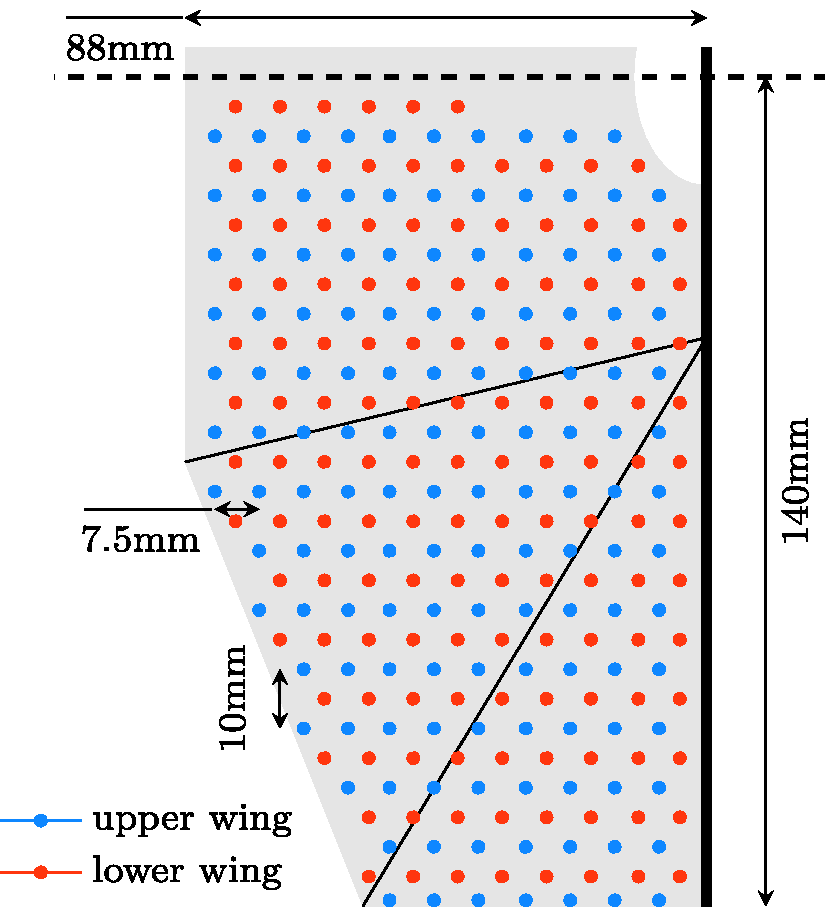
Schematic of DelFly wing half with point grids.
Point tracking algorithm
The recorded images are processed using a point tracking algorithm coded in MATLAB. Essentially, the algorithm uses a temporal tracking method to follow the image point movements, which are then triangulated to obtain the world locations. As the points are practically indistinguishable, small errors in the exact point location can over time lead to larger errors when a point snaps to an incorrect one. This is problematic, especially as the path of points of the two wings often cross. Therefore, the known point spacing is used to reduce noise in the predictions and to detect errors. Once a full flapping cycle is measured, these measurements are used as predictions for the following cycles. This allows the algorithm to run fully automated, with only some initial manual input.
The following paragraphs explain the algorithm in more detail.
Initially, the images recorded in the LaVision software DaVis are imported into MATLAB and pre-processed, which includes distortion correction, background removal using separately recorded images, image inversion, and Gaussian smoothing with a 7 pixel × 7 pixel kernel size. The camera model necessary for distortion correction and later triangulation is created using the MATLAB stereo camera calibration toolbox.
A two-stage circular Hough transform (CHT) method 17 is used to detect the wing points, starting with a recording where the wings are in contact and almost orthogonal to the camera view. One point per wing must be selected manually, the following will then be detected automatically using the known point spacing and an estimated magnification factor. With all points detected in all views, the stereo calibration is used to calculate the world positions.
For the subsequent timesteps, a temporal tracking method is used to predict the point locations. Therefore, an up to third degree polynomial is fitted to the growing time-series, which coefficients can be used to determine the point velocity components (after the first timestep they are assumed to be zero). The velocity vector multiplied by the timestep then gives an estimation of the point pixel shift. As the determined point locations contain some error, noise quickly accumulates in the determined velocities. Therefore, a spatial fit of the velocities is computed using radial basis interpolation using a C2 compact support function. If the difference between the calculated and fitted velocity is larger than the velocity fit itself, the fit is used instead of the calculated velocity. The velocities were normalized with the spanwise point location, analogous to the rotational velocity around the stroke axis, to improve the spatial interpolation.
The true point locations are then determined as the simultaneous correspondence between all point predictions and CHT measurements which minimizes the total prediction error. This simultaneous matching of both wings avoids incorrect correspondence of points which easily occurs when points in close proximity are sequentially corresponded. The optimization is done using a mixed-integer linear programming algorithm, where duplicate use of a measured point is prevented using constraints. If no measurement that fulfills the set tolerance could be found, the point status is set to missing.
These points are neglected in the spatial predictions. Furthermore, in the following timesteps they are corresponded after successfully found points using the world reprojection instead of the temporal prediction. If the point status in one view is considered correct, the prediction in the other view is improved using the epipolar line.
Nonetheless, point correspondences can be incorrect. Therefore, a check for incorrect point measurements is also done in the world domain.Here, a spatial fit of the triangulated points is created using the radial basis interpolation previously used for the in-plane location together with a polynomial fit for the out-of-plane location. Measured point locations, which deviate more than 2.5 mm from the fit, or points that have a reprojection error above 1.5 pixel, are assumed to be incorrectly triangulated.
Once a point exceeds this tolerance by a factor of two, a correction of the triangulation is attempted. For this, the view with lower certainty is selected, which is the view where either no point measurement could be corresponded or where the reprojection of the spatial fit lies further from the measured point location. This incorrect point view is then handled like the missing points described above. The increased tolerance of the correction is used to prevent over-use of corrections without allowing incorrect triangulations to be considered in the spatial predictions.
After a full cycle is measured, the exact cycle length is determined which allows to combine the measurement series to a single cycle. This series is then resampled, thereby filling gaps where points could not be found, to create a prediction for the following cycles. This cyclic prediction is improved with each full cycle as new measurements are added.
The complete measurement series is low-pass filtered using a MATLAB function to remove noise. The cut-off frequency was set to the 10th flapping harmonic, i.e. between 100 and 130 Hz, which is conservative compared to the influence limits found in other studies.18,19
Method verification and accuracy
The described algorithm works well in determining the DelFly wing deformation. On average, the reprojection error lies at around 0.21 pixel with 3.4% point tracks are determined to be incorrect based on the mentioned criteria. The tracking quality is thereby lower for the second cycle half and the lower wing as point motions are possibly less favorable and larger points are more often occluded by stiffeners. Worse tracking results in isolated false positive point measurements, which increase the mean reprojection error.
Measurements of a 150 mm diameter reference sphere were done to get a better understanding of the general setup accuracy. The 63 markers of 1 mm radius had an average reprojection error of 0.11 pixel and could be fit to a sphere with a standard deviation of 0.13 mm. Assuming a linear relation with the reprojection error, the deformation measurements can be said to be accurate to approximately 0.25 mm.
Airfoil parameter definition
The following discussion uses the measured points to represent the wing surface, i.e. the most forward and backward points are used as wing leading and trailing edge, respectively. To obtain equivalent parameters, the points on the lower wing are interpolated to match the upper wing. The total of 2000 measurements is allocated to 100 phase bins over the flapping cycle to calculate the deformation statistics. The phase is thereby indicated by the non-dimensionalized time,
The point measurements are transferred from the body coordinate system to a wing coordinate system fixed to the wing leading edge shown in Figure 4(a). An exemplary

Used coordinate systems. (a) Sketch of the DelFly including body (red) and local wing (green) coordinate systems and dihedral plane (blue) and (b) definition of wing airfoil parameters in normalized
The wing coordinate system is also used to calculate different local wing airfoil parameters.The camber ratio,
Wing deformation in forward flight
Horizontal forward flight of the DelFly is achieved by pitching the MAV forward. This results in a horizontal component of the forces produced by the flapping wings, which typically act in
Tethered flight settings representing free forward flight.
General wing deformation
A representation of the temporal development of the wing deformation is given in Figure 5. The spanwise location,

Wing airfoil deformation at
The characteristic clap-and-peel motion can be seen in Figure 5(a), where between
Apart from this, in all cases a mean incidence angle directed toward the freestream direction is clearly present. Also, it can be seen that airfoils flatten as they move in positive while camber increases during movement in negative direction. To better describe the movement relative to the axis and freestream direction, the terms up- and downstroke are introduced. These correspond inversely to in- and outstroke for the upper and lower wing. Especially in fast forward flight the airfoil deformation relates mostly to the up- and downstroke. The predominantly flat airfoils during the upstroke (left to right movement) in Figure 5(d) show this clearly. A good indication of the asymmetric deformation is the freestream component in
Interesting to see is that the core clap-and-peel deformation remains relatively unaffected by the pitch angle and appears to be simply rotated to a twisted wing contact plane. Due to this rotation, the leading edge path of the lower wing (shown on the left) is directed considerably more backwards, which results in an asymmetric heave of both wings. The wings are heaving more during the downstroke, which typically indicates higher loads during this phase.
Airfoil parameters
The wing airfoil parameter plots shown in Figure 6 give further insight into the deformations.
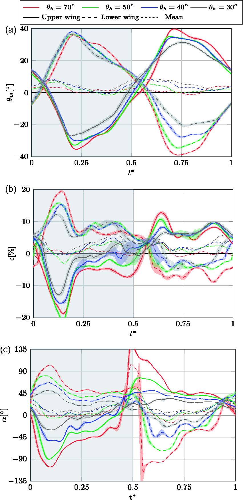
Wing airfoil parameters at
As seen before, the incidence angle peaks around the middle of each stroke for all cases. In the outstroke phase, the peak occurs at the end of the clap-and-peel, when the trailing edges detach. This is followed by a rapid acceleration of the trailing edges, which quickly exceed the leading edge velocity and thus reduces the incidence angle. The large acceleration is likely due to the elastic forces build-up during the clap-and-peel phase.
In all cases, the mean incidence angle of the two wings is positive over most of the cycle, especially for the cases with a large normal freestream component. This is especially prominent during stroke reversal, where the inflow velocity is almost entirely made up by the freestream velocity. The positive mean occurs also as the incidence during the upstroke (negative
Small variations of the incidence angle during the clap-and-peel phase show that this phase is relatively unaffected by the asymmetric inflow. The only difference is a small shift in the initial incidence angle, which was seen as a rotation of the symmetry plane, while the rate of incidence angle increase remains identical.
The assumption that the clap-and-peel behavior is largely unaffected is also supported by the measured camber deformation. While initially both wings have positive camber ratios, between
Larger asymmetries occur outside the clap-and-peel phase. During the downstroke similar positive camber ratios occur for all cases; however, during the upstroke the camber ratio reduces approximately proportional to the pitch angle, approaching zero for the
Looking closely at the airfoil shape in Figure 5(d), it shows that here the upper wing has an S-shape toward the end of the upstroke. At the leading edge the airfoil is already curved upwards, while the trailing edge is still curved downwards. Toward the wing tip this behavior is increased where the entire airfoil inverts already before the stroke reversal. The developing S-shape makes the determination of the camber direction difficult, which leads to large s.d. in this instance.
This phenomenon can be better understood when considering the wing loading, which can be estimated using the calculated angle of attack given in Figure 6(c). While
Apart from this, the angle of attack further strengthens the assumption that the clap-and-peel phase remains a symmetric phenomenon, as the lower and upper wing show a similarly large angle of attack. Large angles of attack above 45° in all cases indicate the production of LEVs, even in the fastest forward flight case. Together with the alignment of the clap-and-peel motion with the flight direction, this suggests a major part of the required thrust is being produced in this phase.
The large spike in
Individual parameter study
As the MAV is tethered in a windtunnel, the effects of changing
Varying flapping frequency in steady ambient conditions
The influence of flapping frequency variation has already been investigated in studies of the DelFly in tethered hovering flight. 7 It was found that an increasing flapping frequency at zero freestream velocity results in a large increase in the incidence angle, heaving motion, and camber production. Also, the trailing edge stroke is reduced and delayed in phase. These effects are linked to an increased wing loading due to the faster motion which outweighs the reduction of angle of attack in these cases. Thereby, the camber increases especially during the clap-and-peel phase. The new measurements agree closely with these findings.
As now both the lower and upper wing are measured, some additional findings could be made. For the forward flight case a presence of a gap between both wing surfaces was already noted. This phenomenon also occurs in the zero-freestream case. Between the measured cases of
Furthermore, the results show asymmetries between the deformation of the lower and upper wing, while previously the deformation was assumed to be purely symmetrical in steady ambient conditions. This asymmetry is clearly visible in Figure 7, for instance during the end of the outstroke, where the lower wing displays camber while the upper wing is mostly flat. Also, the leading edge of the upper wing heaves considerably more during the instroke, while the lower wing heaves approximately identically in both stroke directions.

Asymmetric wing deformation in static ambient condition at
A main reason for this asymmetry can be seen in the dihedral angle of the DelFly. This results in the upper wing tips coming closer to each other compared to the lower wings. This will lead to minor differences in the aerodynamic behavior, as well as asymmetric wing tensioning. Inaccuracies in the manual manufacturing process of the wings may increase this effect and further discrepancies may be introduced by the support and diffusion wall.
Careful study of the spanwise wing deformation showed a torsional wave travelling along the span of the upper wing, which increases the incidence angle quickly at the start of the instroke. A 3D animation of this motion is shown in Video 1 (https://www.youtube.com/playlist?list=PL_KSX9GOn2P-hxC4vUo07Kg7u8V8tOBkE). This spanwise variation is also seen in other flapping-wing fliers.
13
At
Varying symmetric freestream velocity
Next, the effect of increasing freestream velocity aligned with the airframe was investigated. The symmetric external flow approximates vertical climbing flight, a state that is not achievable with the DelFly II as it requires additional flow over the tail to maintain stability. However, a tailless variation of the DelFly that has been developed recently can sustain such condition more reliably, 20 making the case of further interest.
Key wing deformation parameters at different
Variation of wing deformation parameters at

Increasing the freestream velocity from
During the clap-and-peel, the incidence angle also shows little variation due to the changing freestream velocity, as it increases and peaks almost identically for all cases. Also during the remaining outstroke, the incidence angle shows little variation, which is likely due to the release of stored elastic forces. Only a minor phase delay in the incidence angle can be seen, similar to that found in the hover case. 7 Here, this delay can be linked to a larger stroke angle of the leading edge during the hover case, while the trailing edge stroke remains almost identical.
Compared to this, the incidence angle during the instroke varies considerably more, with
The combination of flapping frequency and freestream velocity variation is often described by the reduced frequency,
This becomes evident when adding the individual effects of
Varying pitch angle
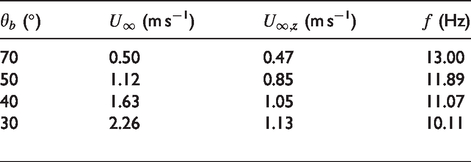
Lastly, the effect of varying pitch angle was studied. The measured cases are shown in Table 3, where
Variation of wing deformation parameters at

The camber ratio shows asymmetries especially during the fast stroke phases, where at larger pitch angles the camber is increased during the downstroke while the wing flattens during the upstroke. During the clap-and-peel the effect is actually inverse, which is likely due to the alignment of the symmetry plane with the inflow motion, as already noted in forward flight. In general, the asymmetric camber effects align quite well with coupled forward flight; also the limited recoil effect is visible in the upper wing.
The mean incidence angle also increases at larger normal freestream velocities, as it was the case in forward flight. Magnitudes are comparable; however, here these peaks occur only around the stroke reversal, compared to a more constant positive mean incidence angle in forward flight. This is likely due to the coupling with the changing flapping frequency and freestream component, where the delta in incidence angle already showed to scale poorly.
Interestingly, the increased asymmetry also has a large influence on the clap-and-peel wing gap. The 0.9 mm difference between the
Conclusion
An optical measurement setup was developed which co-aligns the tethered DelFly with a camera pair and background light. This allows to maintain adequate viewing axes of the wings as they undergo large stroke angles.As the wings are transparent, 136 points applied to each wing could be measured simultaneously. The points were tracked using a purpose-built point tracking algorithm, which uses known structural information to enhance the temporal tracking so that false point matches are mostly avoided. The general accuracy lies around 0.25 mm based on reference sphere measurements. The developed setup and measurement algorithm may be useful in the future for investigating different flight states or other models and may also be an important tool for optimizing wing designs and generating validation data for numeric methods.
Using the developed measurement setup, the DelFly wing deformations were measured in simulated free flight conditions. The measurements show behaviors which to the best of our knowledge have not yet been noted in literature on interacting flapping wings. First, measurements show that the wing surfaces do not touch during the clap-and-peel phase, instead an air-buffer remains at all times. Along the chord at
The forward flight study shows that asymmetries are especially large in fast forward flight. The clap-and-peel by itself is thereby mostly unaffected, most noticeable is only the rotation of the symmetry plane to align with the inflow direction. This indicates that the produced LEV has a dominant effect over the asymmetrical freestream velocity and that the flapping motion likely remains as effective as in hover. Outside the clap-and-peel a positive mean incidence angle and camber ratio is present. Especially during the upstroke the incidence angle and camber are reduced. This indicates reduced wing loading, which is also supported by the measured angle of attack and is also common in insect flight.4,6 For slow forward flight, a recoil and torsional wave motion was noted to occur at the start of the instroke of the upper wing.
Additionally, the individual effects of varying flapping frequency, freestream velocity, and pitch angle were studied. The results strengthen the assumption of non-linear effects, as superposition of the individual effects showed to represent coupled forward flight only poorly. To an extent, the deformation during clap-and-peel appears to be an exception, as it is strongly coupled to the flapping frequency. Apart from the clap-and-peel, the freestream velocity shows a larger influence on the camber and incidence angle. While the release of elastic energy stored in the clap-and-peel phase still shows an impact, the reduced aerodynamic wing loading due to lower inflow angles drives the reduction in incidence angles and camber ratios. The pitch angle meanwhile affects the mean incidence angles and camber of both wings. However, the magnitude is considerably different from the forward flight and is also limited to shorter durations around the stroke reversals. Furthermore, the isolated study also proved that the wing deformation is asymmetric even in steady ambient conditions. Additional studies should be done to understand the absence of the recoil effect in the lower wing. Modifying the design to obtain the same effects as in the upper wing may allow to increase the thrust production in slow forward flight further.
Generally, the carried out measurements give a more detailed description of wing deformation in flight of interacting flapping wings which may drive better understanding and design of MAVs in the future.
Footnotes
Declaration of conflicting interests
The author(s) declared no potential conflicts of interest with respect to the research, authorship, and/or publication of this article.
Funding
The author(s) received no financial support for the research, authorship, and/or publication of this article.
References
Supplementary Material
Please find the following supplemental material available below.
For Open Access articles published under a Creative Commons License, all supplemental material carries the same license as the article it is associated with.
For non-Open Access articles published, all supplemental material carries a non-exclusive license, and permission requests for re-use of supplemental material or any part of supplemental material shall be sent directly to the copyright owner as specified in the copyright notice associated with the article.