
Abstract
This paper presents a novel collision-free navigation system for the unmanned aerial vehicle based on point clouds that outperform compared to baseline methods, enabling high-speed flights in cluttered environments, such as forests or many indoor industrial plants. The algorithm takes the point cloud information from physical sensors (e.g. lidar, depth camera) and then converts it to an occupied map using Voxblox, which is then used by a rapid-exploring random tree to generate finite path candidates. A modified Covariant Hamiltonian Optimization for Motion Planning objective function is used to select the best candidate and update it. Finally, the best candidate trajectory is generated and sent to a Model Predictive Control controller. The proposed navigation strategy is evaluated in four different simulation environments; the results show that the proposed method has a better success rate and a shorter goal-reaching distance than the baseline method.
Introduction
Autonomous navigation in cluttered environments is a key challenge in the area of robot navigation. It is still an unsolved problem because of the requirements of robust perception, planning, and control algorithms when robots operate in an unconstrained environment. During the last years, this problem has attracted a lot of researchers’ attention and several methods have been proposed. In the literature, algorithms have been proposed, the learning-based strategies for autonomous navigation are described in Sampedro et al. 1 and Carrio et al. 2 The autonomous quadrotor aerial robots for solving indoor missions are built by Sampedro et al. 3 and Rigter et al., 4 while the authors of Oleynikova et al. 5 and Cui et al. 6 give solutions for outdoor navigation. A cooperative navigation approach using tiny flying robots is explained in McGuire et al. 7
In our previous works, we have proposed several localization,8,9 control, 9 and collision avoidance algorithms10,11 for safe navigation in the unknown cluttered environments. In this work, we try to develop a robust planner and combine it together with the other algorithms to perform the task in cluttered environments. Compared with other works, our planner only uses a limited field of sensing view and can be used in unconstrained environments.
The planner we develop for the autonomous navigation system can be thought of as a local planner. First, we generate finite path candidates with rapid-exploring random tree (RRT) in a three-dimensional (3D) bounding box. Then, the optimal path from the path candidates is selected using a modified Covariant Hamiltonian Optimization for Motion Planning (CHOMP) objective function 12 . Finally, we generate the trajectory with the optimal path and track the trajectory using a Model Predictive Control (MPC) controller.
The innovations in our work are listed below:
First, we develop a robust local planner which uses a RRT-based online path candidates generation algorithm and a modified objective function of CHOMP to select an optimal candidate. Then, the local planner is combined with the localization, perception, trajectory optimization, and control algorithm to build a fully-autonomous navigation system.
The remainder of the paper is organized as follows. The related works are covered in Section “Related works”. Section “Problem formulation” presents the problem formulation. In Section “Methodology”, the proposed methodology is introduced. We describe the experimental results and the discussion in Section “Experimental results and discussions”. And finally, Section “Conclusions and future works” concludes the paper and summarizes future research directions.
Related works
A lot of methods have been proposed during the last decades addressing the problem of autonomous navigation in cluttered environments. Fang et al. 13 developed a two-layer fusion framework and combined it with an online motion planning algorithm to build an autonomous navigation system. The experimental results show their system can go through a very narrow doorway in an environment in complete darkness or full of light smoke. Sampedro et al. 3 developed a fully-autonomous aerial robotic solution for indoor exploration and inspection. Their solution was validated in the 2016 International Micro Air Vehicle Competition. Lin et al. 14 built an autonomous navigation system with only a fisheye camera, a low-cost inertial measurement unit (IMU), and heterogeneous onboard computing resources that comprised the minimum sensor suite allowing autonomous flight. The experimental results show that their autonomous navigation system can fly both in indoor and outdoor environments. Mohta et al. 15 designed an autonomous navigation system that is capable of fast aerial navigation through cluttered GPS-denied environments. The experimental results show that their robot can fly without collision in a cluttered environment with speeds of up to 7 m/s. Gao et al. 16 developed a framework for online generating safe and dynamically feasible trajectories directly on the point cloud. Oleynikova et al. 5 created a system using a local planner architecture that could generate smooth global trajectories, locally explore unknown spaces, and deal with changes in a map by actively replanning. As the planning system is the central work of this paper, we discuss in detail the recent relevant planning algorithms in the rest of the section. Generally, the planning system is organized by a path planning system and trajectory generation system.
Path plan algorithm
Generally speaking, sampling-based algorithms and search-based algorithms are two main types of path planning algorithms used in the planning system. The most relevant sampling-based algorithms, RRT, 17 RRT*, 18 and their extended versions 19 are widely used for the path planner in the planning system. In the work of Bircher et al., 20 they use RRT to generate a finite iteration random tree and execute the first edge of best brach. The point clouds-based navigation framework designed by Gao et al. 16 use a safe-region RRT* to generate safe corridors and update it following the principle of anytime RRT*. Then, the trajectory is generated using the updated corridors. The continuous-time trajectory optimization approach 21 plans a dynamically feasible polynomial trajectory based on the path from an Informed RRT* algorithm. There also many planning systems using search-based algorithms like A*, D*, or others to plan the path. Gradient-based online safe trajectory generation strategies 22 use A* to search a minimum distance path on a random-exploring graph. The navigation system using monocular visual–inertial fusion from the same group 14 also applies A* to plan a path for trajectory optimization. Tordesillas et al.23,24 presented a real-time trajectory planner using Jump Point Search (JPS) to find the shortest path from the current position to the goal. The reason they chose JPS is that JPS could run an order of magnitude faster than A* while guaranteeing completeness and optimality.
Trajectory generation and optimization
Based on the path from the path planner, a trajectory optimization algorithm is used to generate a feasible trajectory. Gradient-based strategies like CHOMP use an objective function based on smoothness and safety to punish the waypoints in the path. The final trajectory is generated until the result of the objective function is less than a threshold value or the iteration times are bigger than the maximum times. Recently, a gradient-based online safe trajectory generation method proposed by Gao et al. 22 and the trajectory optimization approach 25 proposed by Oleynikova et al. also applied the gradient-based method for trajectory generation and optimization. The works of Tordesillas et al.23,24 use a control-based method. They consider the dynamic model of the aerial robot and generate the jerk-controlled primitive trajectory by solving a convex optimization problem.
The minimum trajectory generation 26 proposed by Mellinger and Kumar shows that the trajectory generation problem can be thought of as a quadratic programing (QP) problem. Charles et al. 27 extend the minimum trajectory generation problem to a numerically stable un-constrained QP problem. They combine an RRT* planner with the minimum-snap technique to perform fast, graceful flight trajectories while considering collisions. The mixed integer quadratic programing 28 approach proposed by Mellinger et al. uses integer constraints to enforce collision avoidance. The iterative regional inflation by semidefinite programing 29 algorithm developed by Deits and Tedrake is used to pre-compute convex regions of safe space. In recent years, the work from Zhou et al. 30 relies on the use of a B-Spline for trajectory generation and optimization. The experiments’ results show their approach can improve the efficiency and convergence rate of trajectory optimizations.
Problem formulation
This section describes in detail the robot architecture and the environment within the navigation problem. The model of the robot is given at first and then the definition of the environment is explained.
Robot architecture
The robot used in the research is a multirotor unmanned aerial vehicle (UAV). The multirotor UAV has six Degrees of Freedom (DoF), three translation DoF, and three rotation DoF. The on-board sensors of the aerial robot are a front-looking depth (Intel RealSense d435i) and an IMU sensor.
Environment definition
The simulation environments used in this work are environments with multiple obstacles. The mission has a starting point Ps and goal point Pg. The positions of the obstacles are totally unknown when the robot starts to move and the robot can only perceive a fraction of the environment around it. The navigation mission is moving from the starting point to a spherical region centered on the goal point without colliding with the obstacles. An example of the environment used in the paper is shown in Figure 1.
An example of the schematic diagram of the defined environment.
Methodology
There are three main parts in the navigation system, which are
For the localization system, it is built based on our previous work.8,9
For the perception system, we use a depth/RGB-D sensor get point cloud and voxblox Robot Operating System (ROS) package 31 to build the occupancy map. With the occupancy map, we can build the 3D Euclidean Signed Distance Fields (ESDFs) which provide the nearest distance to the occupied voxel and the gradient of each voxel for planning. A scheme describing that shows the perception system can be found in Figure 2.

The proposed approach for perception relies on obtaining a point cloud using a depth/RGB-D sensor. This point cloud is then converted into a more efficient representation, an occupancy map.
For the planning system, a local planner is proposed to plan the trajectory in the field of view (FOV) and guide the robot moving from the starting point to the goal point. The remainder of this section will describe the planning system in detail. First, we generate the path candidates using an online path candidates generation algorithm. Then, the optimal path is selected from the candidates. Finally, we get the trajectory from the optimal path and a trajectory controller is used to move the robot.
Candidate path generation using RRTs
We use RRT to generate the path candidates in a 3D bounding box. RRT is a sample-based planning algorithm using the random sampling in the search area and building connections between the random samples and the nearest state in the tree.
It can be seen from algorithm 1, we keep adding new nodes in the tree until the number of the nodes reaches the preset maximum number. We set the maximum number of the nodes because we want to generate the path candidates within a limited time. PR is the current position of the robot and Pathc are the path candidates generated by the algorithm.
1: 2: 3: 4: 5: 6: 7: 8: 9: 10: 11: 12: 13: 14: 15: 16: 17: 18: 19:
Optimal path selection using a modified CHOMP objective function
After getting the path candidates, a modified CHOMP objective function is used to select the optimal path.
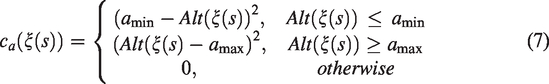
The objective function measures four different aspects of the trajectory planning problem. First, in order to get a smooth path, we add a penalty based on dynamical criteria to the trajectory. Next, we penalize the trajectory based on the distance from the trajectory waypoint to the objects to make the trajectory collision-free. Then, the end of the trajectory is penalized based on the distance from it to the final goal, which can help the trajectory planner plan a trajectory close to the final goal ξg. Finally, we penalize the trajectory by the distance from its waypoint to the ground to make the trajectory inside the predefined minimum and maximum altitude. We describe these four items by fs, fo, fg, fa, respectively, and define the objective function by summing their weights

As described above, the trajectory is ξ and
The objective functions of fs, fo, fg are the same from Fang et al.
13


The altitude objective function

We calculate the cost of every path candidate by using the proposed objective function and select the path candidate with the minimum cost as the optimal path.
Trajectory generation and controller
After getting the optimal candidate, we use it as an initial path for the CHOMP planner to generate the final path.
After getting the path, a polynomial micro aerial vehicle trajectory generation approach 27 is used to generate the trajectory with the final path, and then a MPC 32 is used to track the trajectory.
Experimental results and discussions
Experimental setup
In this subsection, we introduce the experimental setup for the simulation experiments.
We run the simulation experiments using the ROS
33
on top of Ubuntu 18.04. The Gazebo simulator is used to provide the environment model and the RotorS simulation is used to provide the physical model parameters of robot. All the experiments run on a laptop with Intel Core i7-8750H at 2.2 GHz. The simulation of the proposed navigation system is integrated into our open source framework Aerostack (www.aerostack.org). The robot in the simulation is the AscTec hummingbird, which is equipped with a depth sensor with a FOV of
Simulation experiments
In order to evaluate the proposed planning system, we test it in four different environments. These environments are an office environment and three dense forest environments with different obstacle densities. The three dense forest environments have an obstacle density of 0.02, 0.05, and 0.1
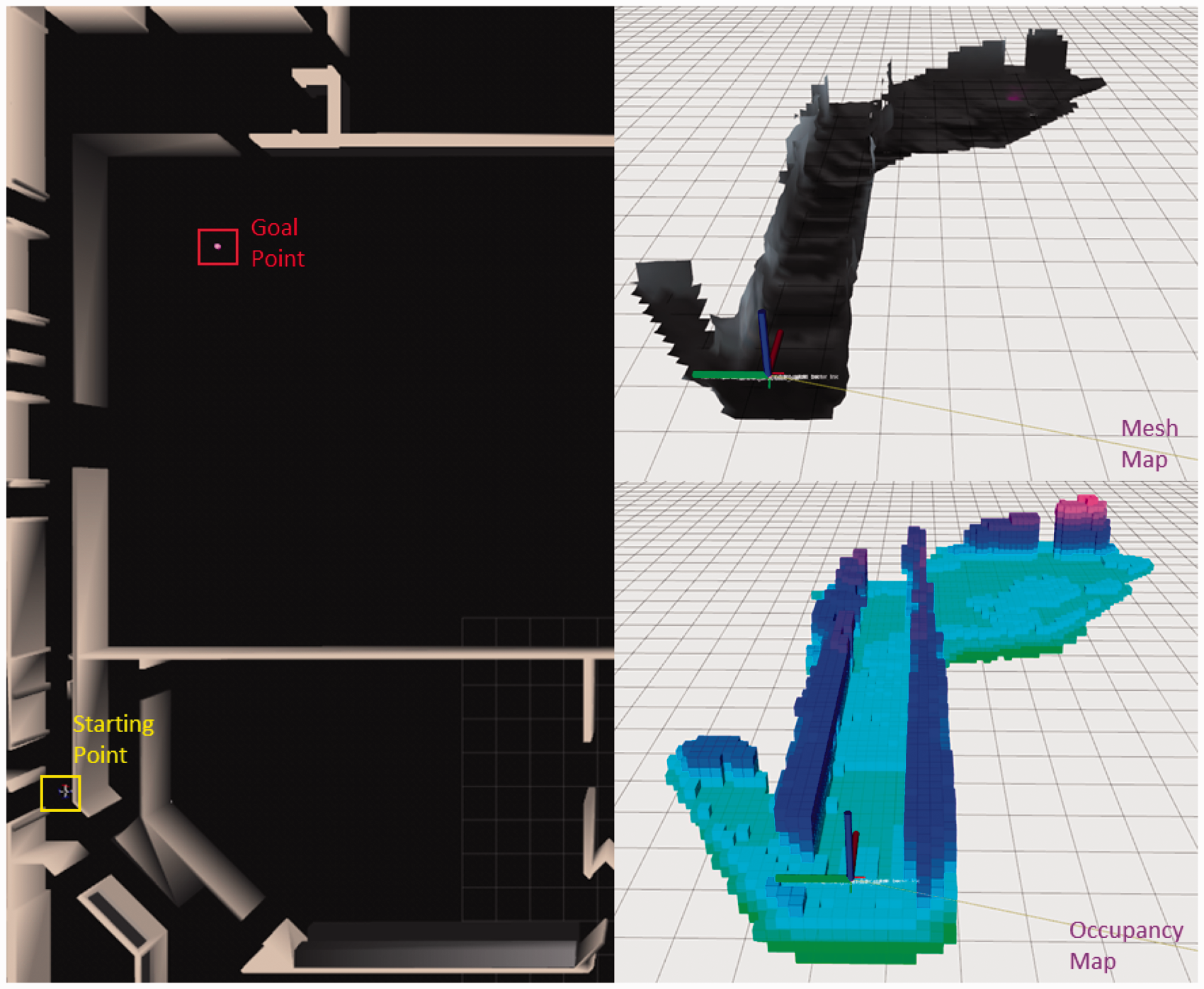
Figure 3 shows the simulation environments used in the paper. The trajectories of one successful run of each environment in the mesh and occupancy map are also shown.

The office and three dense forest environments used for simulation experiments. The large figure corresponds to a top-view of the environment. The smaller top figures show the mesh maps and the bottom ones the occupancy maps.
We run the proposed algorithm 50 times in each environment. For each run, the starting point and goal point are randomly generated in a prior defined range. The starting point in the office environment is generated from
The experiment results of the proposed method in the Gazebo environments which are shown in Figure 3.

DF: dense forest; SR: success rate; TL: length of the trajectory; TG: time to reach the goal; AV: average velocity; AMV: average maximum velocity.
We compare the proposed algorithm with a baseline method. We build the baseline algorithm using RRT* to generate candidates and chooses the candidate based on a goal-biased objective function. 34 For the comparative experiment, We run the baseline algorithm 50 times in the office and in three different dense forest environments. Then, the success rate and the trajectory lengths are obtained for evaluation. The trajectory lengths are computed for the cases in which the goal is reached.
A video showing one fail and success running in the office and DF (
Discussions
As can be seen from Table 1, the proposed planner has good successful rates in all the simulation environments. The success rates are 90%, 96%, 94%, and 90% in the office, DF (
Figure 4 shows that the proposed strategy can plan a shorter trajectory to reach the goal. The average distance values obtained by our planner are 19.2 m in the office environment and between 76.2 m and 78.0 m in the dense forest environments. The average distance values obtained by the baseline method are 24.03 m in the office environment and between 102.62 m and 109.05 m in the dense forest environments. As can be seen from Figure 5, the proposed method has much better performance than the baseline method. The success rates of baseline method can only reach 58%, 48%, 62%, and 72% in the office, DF (

Trajectory length obtained by the proposed method and the baseline method in the dense forest and office simulations. The values of covered distance are computed for the cases that reach the goal.

The success rate of the proposed method and baseline in the in the office and dense forest simulations.
The main differences between the proposed method and the baseline strategy are that it designs an objective function for best candidate selection and updates the selected candidate using the CHOMP objective function before sending it to the controller. The experiment results show that the proposed approach helps planner find a shorter trajectory and improve the success rate to reach the goal.
Conclusions and future works
In this paper, a method for aerial robot autonomous navigation in cluttered environments has been presented. First, the depth sensors are used to sense the environment around the robot. Second, the occupied map is built using the point clouds captured with the sensors. Finally, a local planner is developed to plan a feasible trajectory and send it to a MPC controller. The local planner uses RRT to generate path candidates and a modified CHOMP objective function to select the best candidate. In order to improve the quality of the selected candidate, the CHOMP objective function is used to update it before sending it to the controller. The experiment results show that the proposed method has a better success rate and covers a shorter distance to reach the goal.
In the future, our work will focus on improving the success rate and high-speed navigation in cluttered and dynamic environments. We will combine the search-based algorithm like A* with the safe flight corridor to plan the trajectory for aggressive flight. A real flight will also be implemented in the future.
Footnotes
Declaration of conflicting interests
The author(s) declared no potential conflicts of interest with respect to the research, authorship, and/or publication of this article.
Funding
The author(s) disclosed receipt of the following financial support for the research, authorship, and/or publication of this article: The work reported in this paper is sponsored by the Chinese Scholarship Council (CSC) and by the project “COMplex Coordinated Inspection and Security missions by UAVs in cooperation with UGV”, funded by the Spanish Ministry of Economy and Competition (RTI2018-100847-B-C21).