
Abstract
The present paper aims to investigate numerically small amplitude oscillation of NACA 0012 airfoil at Re = 1000. The airfoil is sinusoidally pitching around the quarter chord point with 1° pitch amplitude about a mean angle of attack. The computations are performed for mean angles of attack ranging from 0° to 60° and for pitching frequencies of 1 Hz and 4 Hz. The effect of the mean angle of attack and pitching frequency on the instantaneous forces as well as the vortex structure is investigated in comparison with the non-oscillatory conditions. It was shown that airfoil oscillations at the investigated conditions change the amplitude of oscillation of the aerodynamic loads. The instantaneous drag coefficient is always positive for pitching airfoil at 1 Hz. In the meantime, there are time intervals where instantaneous drag coefficient becomes negative for pitching motion at 4 Hz for mean angles of attack from 3° to 36°.
Introduction
Flapping wing micro air vehicles (MAVs) become much more effective than fixed-wing MAVs as the size of these vehicles decreases.1–3 The investigation of the unsteady aerodynamics of pitching airfoils is important for the investigation of animal propulsion, MAV industry, and also for the performance of rotorcrafts 4 and wind turbine blades.5,6 There have been extensive studies in recent years on the flapping wing aerodynamics at low Reynolds (Re) numbers.1,7–9
Pure pitching airfoil is investigated widely at high Re numbers above 50,000.10–15 Kim and Chang 16 investigated with smoke-wire flow visualization technique sinusoidally pitching NACA 0012 airfoil at Re = 23,000, 33,000, and 48,000 with an oscillating amplitude of 6° and zero mean angle of attack at a reduced frequency of k = 0.1. They have also measured unsteady pressure through the pressure correction with pneumatic tubing.
Freymuth 17 investigated the propulsive wake patterns after NACA 0015 airfoil in pure pitching motions for a reduced frequency of 2.9 and Re number of 12,000. Thrust is generated rather than drag in the case where the jet-like velocity components are observed at the downstream of the airfoils in plunging or pitching motions.
Koochesfahani 18 experimentally showed the vortical flow patterns in the wake of NACA 0012 airfoil pitching at small amplitudes in a water channel. The experiments are performed at Re = 12,000. It is concluded that oscillation frequency, amplitude, and waveform shape affect the structure of the wake. At low frequencies, an undulating vortex pattern is observed. At higher frequencies, an alternating vortex pattern is observed opposite to typical Karman vortex street which corresponds to a jet pattern. This vortex arrangement corresponds to the thrust generating airfoil. He also observed a case with no momentum deficit in the wake (no drag) when the alternating vortices are positioned exactly on a straight line. Thrust producing flapping airfoils at different flapping amplitude and frequencies are also presented by Lai and Platzer 19 experimentally.
Bohl and Koochesfahani 20 investigated experimentally the flow structure in the wake of a NACA 0012 airfoil pitching around the quarter chord point at a pitch amplitude of 2° about a zero mean angle of attack, and at Re = 12,600 using molecular tagging velocimetry technique. The frequency of oscillations is in the range of 1.18 Hz to 3.21 Hz which corresponds to a reduced frequency of 4.1 to 11.5.
Force and particle image velocimetry (PIV) measurements are performed on NACA 0012 airfoil undergoing small amplitude plunge oscillation at Re = 10,000 by Clever et al. 21 They found that local maxima for the lift coefficient occur due to the resonance with the most unstable wake frequency, its subharmonic and first harmonic.
Kurtulus et al. 22 investigated experimentally pitching and plunging NACA 0012 airfoil at Re = 1000 and compared the results with 2D numerical simulations.
Recently, Tian et al. 23 performed experiments in a closed-circuit low-speed wind tunnel with a symmetric NACA 0012 airfoil model undertaking a sinusoidal pitching motion with 5° pitching amplitude at zero mean angle of attack and at Re = 3400. The pitch-pivot-point location was changed from 0.16c to 0.52c with the reduced frequency of the pitching motion ranged from k = 3.8 to 13.2. A high-resolution digital PIV system was used to quantify the evolution of the unsteady vortex structures in the wake behind the pitching airfoil.
The effect of the wake patterns for a single flat plate in pitching oscillation motion is studied numerically using a discrete vortex method by Han and Cho 24 to investigate possible thrust generation mechanism. They have also investigated two flat plates in pitching oscillations.
Jones et al. 25 showed comparison of their panel code results with linear theory of Garrick until reduced frequencies of 20. The efficiency of pitching airfoils converges to 0.5 as a result of linear theory, but panel code reveals lower efficiency values as small as 0.2 for k = 20. 25
Sarkar 26 investigated the effect of non-zero mean angle of attack on the wake of NACA 0012 airfoil at Re number of 10,000 during pure sinusoidally pitch and plunge oscillations using a particle-based Lagrangian viscous solver. The definition of effective angle of attack will lead pure plunge case to an equivalent pure-pitch case, but the selection of the mean angle of attack is also an important parameter for the comparison. The wake deflection depends on the total angle of attack and not only the amplitude of the pitching oscillation.
Sarkar and Venkatraman 27 studied dynamic stall of NACA 0012 airfoil with reduced frequencies ranging from 0.5 to 3.0 oscillating at an amplitude of 10° around a mean angle of attack of 15° and oscillating at an amplitude of 20° and mean angle of attack of 25°. The simulations are performed at Re = 10,000, and it is noted that the pitching angle of an oscillating airfoil in the post stall regime impacts its dynamic behavior significantly.
Medjroubi et al. 28 investigated NACA 0012 airfoil oscillating in heave (plunge) motion at mean incidences of 12° to 20° at 800 ≤ Re ≤ 10,000 solving Navier–Stokes equations using a Spectral/hp Element method for spatial discretization. They concluded that increasing Re number while keeping the same frequency and amplitude of oscillations has no major effects neither on flow structure nor on the aerodynamic loads; however, the mean incidence angle influences dominantly the flowfield. They stated that setting the airfoil in motion has the same effect as for increasing the mean angle of attack for steady airfoils.
Pitching and plunging NACA 0012 airfoil at Re number of 1000 was presented by Khalid et al. 29 They have proposed a novel criterion based on the Strouhal number which provides equivalence of pitching and plunging motions taking into account the length scale traversed by the corresponding trailing edges.
Although there are lots of studies about the vortex patterns at the wake of the airfoils around pitching/flapping airfoils at low Re numbers, the characteristics of the wake patterns are not investigated at small pitch amplitudes around different mean angles of attack. In addition, there are very few data available in literature about pure pitching oscillations at low Re numbers of order 1000. Kurtulus30,31 previously investigated the flow past NACA 0012 and NACA 0002 airfoils at Re = 1000 for steady uniform flow at different incidence angles. She has classified the wake structures into five different modes (Kurtulus modes 32 ) according to their pattern obtained from instantaneous and mean vorticity fields by also taking into account the amplitude spectrum of the lift coefficient, the instantaneous and mean aerodynamic force coefficients, velocity fields, and the longitudinal and lateral vortex spacings. Rossi et al. 32 show that the classification of the wake structures is similarly visualized for Re number ranging from 100 to 3000.
Kurtulus 33 also showed that the mean lift coefficient increases slightly for 1 Hz pitching motion for the mean angles of attack lower than 15°; however, it decreases for 4 Hz pitching motion compared to non-oscillatory airfoil. The lift curve slope at zero angle of attack has been found to be approximately π for NACA 0012 airfoil at Re = 1000 for non-oscillatory condition, and it is found that pitching the NACA 0012 airfoil around zero mean angle of attack at 1 Hz slightly increases the lift curve slope; however, pitching the same airfoil at 4 Hz results a decrease in the lift curve slope.
In the current study, the unsteady flow structures around a pitching NACA 0012 with an amplitude of 1° about a mean angle of attack at a low Re number of 1000 are investigated. The airfoil oscillates sinusoidally in pitch about its quarter chord axis with a frequency of 1 Hz and 4 Hz about the mean angles of attack which varies in the range of 0°–60°. These frequencies are selected based on the previous findings from the amplitude spectrum of the lift coefficient for the non-oscillatory NACA 0012 airfoil at Re = 1000 where a maximum vortex shedding frequency of f = 1.3 Hz was obtained at 9° angle of attack. 30
The main motivation of the current paper was to investigate the effect of the very small disturbances like 1° oscillations to vortex patterns in addition to aerodynamic forces in order to better understand in general the flapping airfoil vortex formation and compare the results with the previous steady airfoil simulations. In order to have an idea about the frequency effect, the results are presented at two different frequencies.
The numerical simulations are performed using a finite-volume-based package program ANSYS Fluent. The flow structure analysis includes the vortex formation, wake shedding frequency, and their effects on aerodynamic coefficients. The vortex patterns at two different reduced frequencies for different mean angle of attacks are compared. Their effects on the instantaneous aerodynamic loads are discussed.
Numerical method
Governing equations and geometry
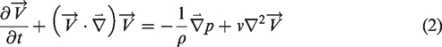
The governing equations are Navier–Stokes equations for incompressible, laminar, and two-dimensional flow

ANSYS Fluent implements the finite-volume method to solve conservation equations. The pressure–velocity coupling is done by means of the SIMPLE-type fully implicit algorithm. Pressure–velocity coupling is used with a predictor–corrector pressure scheme. Transient solution has been approximated using second order implicit method. The solution is second-order accurate in space and time. The velocity inlet boundary condition is used at the semi-circular region of the outer domain, and pressure outlet is used at the other side of the outer region. The far field boundary is located at 15c away from the airfoil.
The instantaneous angle of attack, α, defined to be positive in the clockwise direction was varied sinusoidally (equation (3)) with an amplitude of 1° (A = 1°), and with frequencies of f = 1 Hz and f = 4 Hz around a mean incidence angle (α0). The effect of mean incidence angle is investigated from α0 = 0° to α0 = 60° with an increment step of 1° for α0 < 40° and 10° for 40° ≤ α0 ≤ 60°

The instantaneous angular velocity Ω is given by equation (4)

The pivot point was at the quarter chord location (0.25c) from the leading edge of the airfoil. Reduced frequency is k = 2πfc/U∞ where U∞ = 0.146 m/s, c = 0.1 m, and pitching frequency is taken to be f = 1 Hz and f = 4 Hz which results the reduced frequencies as 4.3 and 17.2, respectively. Re number is 1000.
Grid and time refinement studies have been carried out for steady NACA 0012 airfoil in a previous study by Kurtulus. 30 The steady aerodynamic force coefficients are also compared in this previous study for NACA 0012 airfoil with different data available in literature,34–38 and the results are found to be very similar. In addition, the mean lift and drag coefficients for a thinner airfoil (NACA 0002) were previously compared with the results of Kunz and Kroo 39 which were available for angle of attack values of 0° to 8° at steady conditions. The results are similarly found to be very close to each other. 31 The same number of grid and time increments is also used in the current study. Three hundred nodes are used around the airfoil for the medium mesh selected after the grid refinement study compared to 150 nodes at coarse grid and 500 nodes at fine grid. The first cell spacing of the boundary layer for medium mesh has value of 0.0015c. Total number of elements is order of 200,000. The mesh around the airfoil is composed of two parts, namely inner region and outer region. The inner region above the boundary layer is constructed with a semi-circle having radius of 1.5c centered at the airfoil c/4 location at the upstream and a rectangular region with width of 1.5c at the downstream of the airfoil. The inner region mesh is unstructured triangular grid. The outer domain is of C-type structured mesh. The far field boundary is located at 15c upstream and 19c downstream from the leading edge of the airfoil. With the preprocessor program, the airfoil is rotated for the given angle of attack in the inner region by keeping the outer domain and wake region fixed with the same structured grid. The time refinement study carried out with time increments of Δt = 0.0005 s, Δt = 0.005 s, and Δt = 0.001 s reveals that Δt = 0.005 s in comparison with Δt = 0.0005 s give almost same results; therefore, the current study is performed with time increment of Δt = 0.005 s. This time increment was also selected in the previous studies for steady conditions.30,31 For pitching conditions, the computational time interval is 36 s, and the mean vorticity contours are obtained in the interval of t ∈ [16 s 36 s]. Cl and Cd denote the instantaneous lift and drag coefficients for the airfoil, respectively. It should be noted that for the steady solutions, the results were simulated until t = 100 s, and the mean contours and values were obtained by averaging in the interval of 50 s ≤ t ≤ 100 s.
Results
Unsteady numerical simulation past a sinusoidally pitching airfoil with 1° pitching amplitude at two different pitching frequencies has been performed and compared with the non-oscillatory results. The airfoil is pitching about its quarter chord point.
Mean aerodynamic coefficients
The effect of small amplitude pitching oscillation on NACA 0012 airfoil is already investigated on mean aerodynamic coefficients, 33 and the results are compared with the non-oscillatory simulations of previous studies.30,31 The comparison of mean lift coefficient, mean drag coefficient, and mean lift to drag coefficient ratios for pitching NACA 0012 airfoil at f = 1 Hz and f = 4 Hz are performed in comparison with the non-oscillatory solutions for NACA 0012 and a thinner airfoil NACA 0002 31 at Re = 1000 as shown in Figure 1. The detailed discussion about the mean lift, drag, and lift-to-drag ratios are given in Kurtulus. 33

Mean aerodynamic lift and drag coefficients for NACA 0012 pitching at f = 1 Hz and f = 4 Hz in comparison with the non-oscillatory NACA 0012 and NACA 0002 airfoils at Re = 1000.
It is observed that the mean values are slightly affected by the small amplitude pitching motion of the airfoil; however, there is an important change in the instantaneous aerodynamic forces and specifically in the oscillation amplitudes of these coefficients. The pitching motion also alters the wake shedding behind the airfoil compared to non-oscillatory cases.
Comparison of instantaneous and mean wake patterns
The instantaneous and mean vorticity contours are presented for steady airfoil (Figures 2 and 3), for f = 1 Hz oscillation (Figures 4 and 5) and for f = 4 Hz (Figures 6 and 7) for same angles of attack below 12° to present the oscillation frequency influence to the wake shedding of the NACA 0012 airfoil at Re = 1000.
Instantaneous vorticity distribution for non-oscillating NACA 0012 (t = 100 s) at Re = 1000.

Mean vorticity distribution for non-oscillating NACA 0012 at Re = 1000.
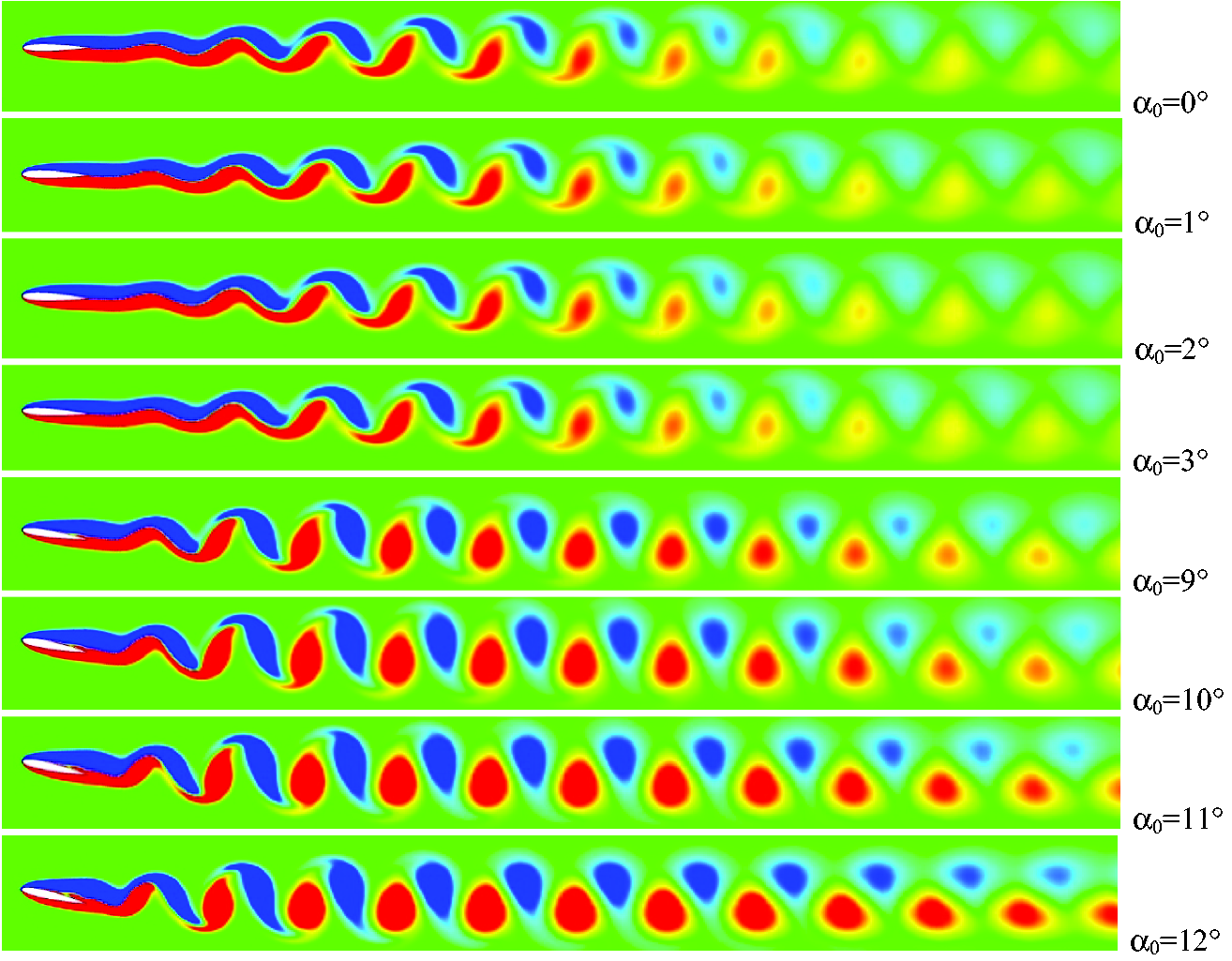
Instantaneous vorticity distribution for NACA 0012 airfoil oscillating at f = 1 Hz (t = 36 s).

Mean vorticity distribution for NACA 0012 airfoil oscillating at f = 1 Hz.

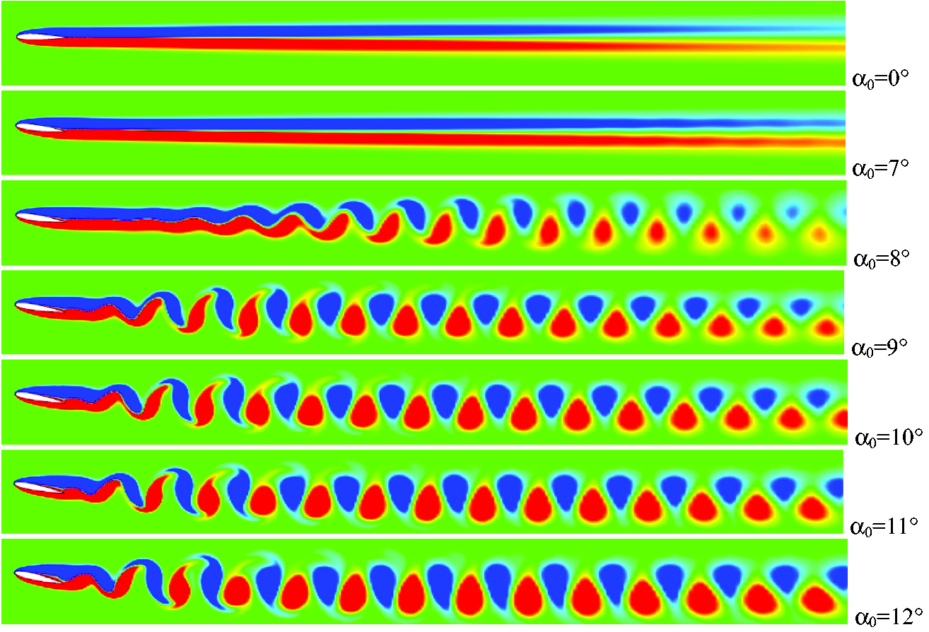
Instantaneous vorticity distribution for NACA 0012 airfoil oscillating at f = 4 Hz (t = 36 s).

Mean vorticity distribution for NACA 0012 airfoil oscillating at f = 4 Hz.
It was previously found that instantaneous and mean vortex shedding are similar and almost straight for the angles of attack less than or equal to α0 = 7° at steady conditions, and a periodic vortex shedding is observed above α0 = 8°. 30 For f = 4 Hz pitching oscillations, the periodic vortex shedding is observed at a higher mean angle of attack of 10° (Figures 6 and 7). In contrast, the periodic vortex shedding can be visualized for all angles of attack of the NACA 0012 airfoil oscillating at f = 1 Hz frequency (Figures 2 and 3).
The instantaneous and mean vorticity distributions for f = 4 Hz are analyzed in Figures 8 and 9 for α0 ranging from 13° to 21°, respectively. The wake pattern of the airfoil is observed to alter at the downstream of the airfoil above α0 = 13°. The amplitude spectrum of Cl at f = 4 Hz reveals also an abrupt increase in the frequency spectrum at α0 = 13° compared to α0 = 12° as shown in Figure 20. The wake height also increases with the mean angle of attack, and the alternating vortices start to merge from the far downstream to the vortices at their upstream as the mean angle of attack increases until α0 = 17°. At mean angle of attack of 18°, a transition of the wake distribution is observed, and at α0 = 21° the vortices start to lose their instantaneous alternating pattern at the far downstream (Figure 8). The mean vorticity contours show the increase of the wake height with the mean angle of attack which is also a reason for the increase of drag coefficient (Figure 9).

Instantaneous vorticity distribution for NACA 0012 airfoil oscillating at f = 4 Hz (t = 36 s).

Mean vorticity distribution for NACA 0012 airfoil oscillating at f = 4 Hz.
The instantaneous and mean vorticity contours at higher mean angles of attack (40° and 60°) are presented in Figure 10(a) and (b), respectively. At high angles of attack it is observed that the shedding frequency decreases, and more K–H vortices are amalgamated to form one Karman vortex.30,40,41

Vorticity distribution for NACA 0012 airfoil oscillating at f = 4 Hz. (a) Instantaneous (t = 36 s). (b) Mean.
Comparison of instantaneous aerodynamic coefficients
Instantaneous aerodynamic coefficients for different angles of attack are presented below for pitching airfoil at f = 1 Hz and f = 4 Hz in comparison with the steady airfoil. It is observed that the instantaneous drag coefficient is always positive for f = 1 Hz simulations (Figures 11 and 15 to18). However, unsteady drag coefficient is always positive for pitching airfoil around 0°, 1°, and 2° mean angle of attacks for f = 4 Hz. Between 3° ≤ α0 ≤ 36°, there are local time intervals where drag coefficient becomes negative (thrust) for f = 4 Hz pitching motion. Transition mean angles of attack are 37° and 38°, and above these mean angle of attacks, the instantaneous drag coefficient is all through positive.

Instantaneous lift and drag coefficients for f = 1 Hz and f = 4 Hz oscillations at α0 = 0°.
The aerodynamic coefficients of the airfoil pitching around α0 = 0° are periodic, and they have sinusoidal patterns both at f = 1 Hz and f = 4 Hz (Figure 11). It is noted that these two cases are the only cases among the simulated results where a period doubling is observed in a sinusoidal form for the drag coefficient.
There is a suction region at the lower side of the airfoil at the beginning of the period where the airfoil pitch down at f = 4 Hz. Figure 12 shows that the lift-to-drag ratio increases during the pitch down motion of the airfoil in the interval of t ∈ [35.5 s 35.56 s]. In this interval, the lift-to-drag ratio increase resulted due to a simultaneous increase in the lift coefficient and decrease in the drag coefficient. Figures 13 and 14 show instantaneous streamlines, gauge pressure contours, and wall gauge pressure on the airfoil at f = 4 Hz oscillation and α0 = 0° during pitch down and pitch up motions, respectively.
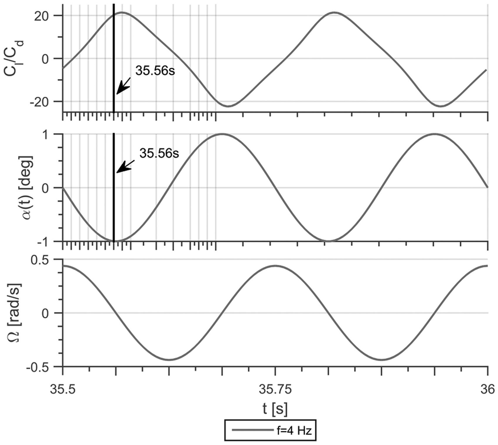
Cl/Cd ratio, instantaneous angle of attack, and angular velocity versus time for f = 4 Hz oscillations at α0 = 0°.

Instantaneous streamlines, gauge pressure contours, and wall gauge pressure at f = 4 Hz oscillation and α0 = 0° during pitch down motion.

Instantaneous streamlines, gauge pressure contours, and wall gauge pressure at f = 4 Hz oscillation and α0 = 0° during pitch up motion.
When the mean angle of attack increases to 1°, a deviation from sinusoidal behavior is observed for the drag coefficient (Figure 15). For the lift coefficient of the airfoil oscillating at f = 4 Hz, the sinusoidal behavior is observed for all cases investigated. However, the amplitude of the sinusoidal function stays constant until α0 = 11° in the quasi-steady region for f = 4 Hz (Figure 16). For the airfoil oscillating at f = 1 Hz, the lift coefficient deviates from the sinusoidal behavior above α0 = 11° as can be observed clearly from Figures 16 and 17.

Instantanous lift and drag coefficients for f = 1 Hz and f = 4 Hz oscillations at α0 = 1°, 2°, and 3°.

Instantanous lift and drag coefficients for f = 1 Hz and f = 4 Hz oscillations at α0 = 8°, 9°, 10°, and 11°.
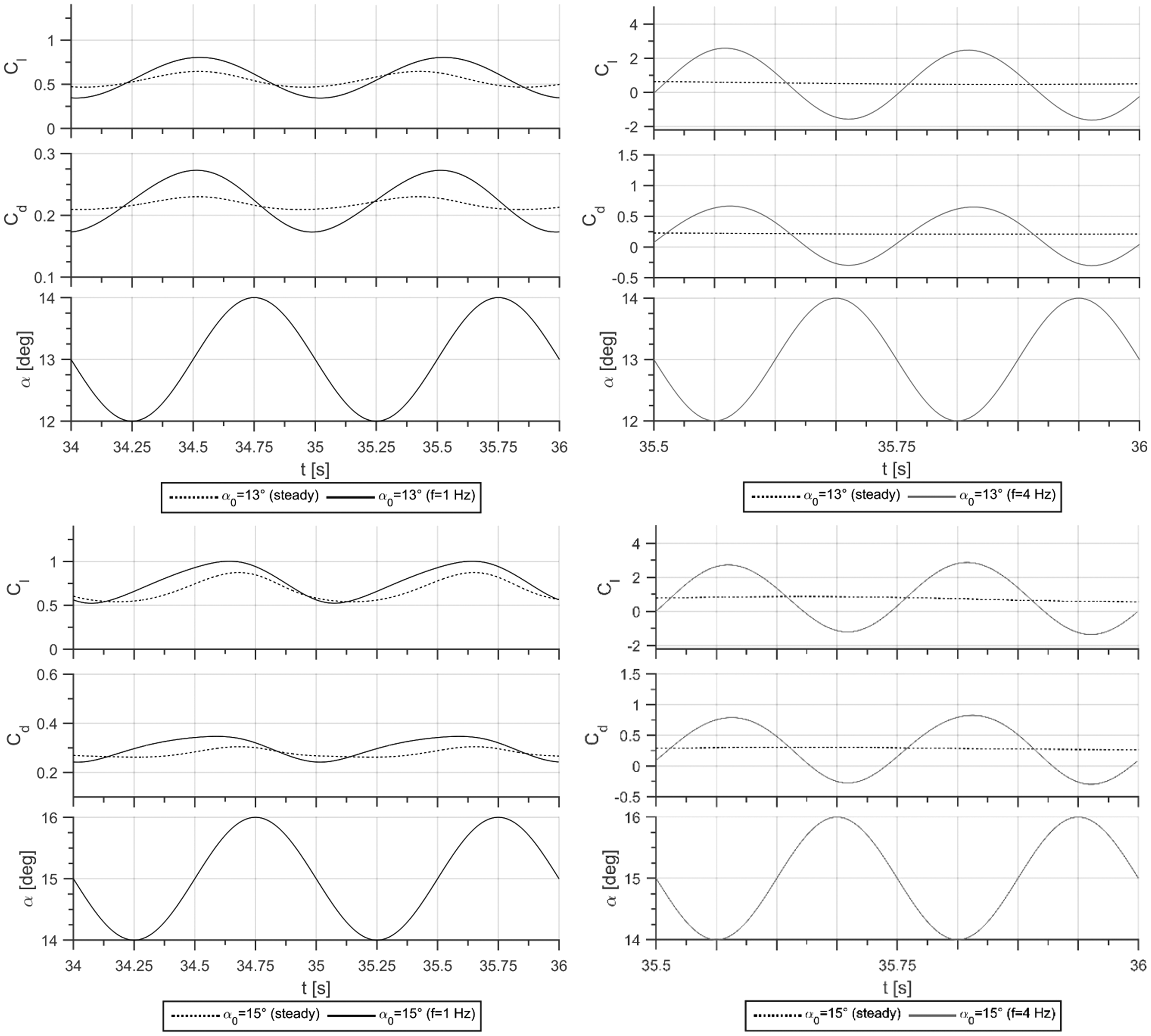
Instantanous lift and drag coefficients for f = 1 Hz and f = 4 Hz oscillations at α0 = 13° and 15°.
The minimum Cd value decreases specifically for f = 4 Hz oscillation, and negative Cd values are observed above mean angles of attack of 3° (Figure 15) until a mean angle of attack of 37°.
Figure 18 shows the instantaneous lift and drag coefficients for higher mean angles of attack (α0 = 40° and 60°). At f = 4 Hz pitching oscillation, the sinusoidal behavior of the lift coefficient is observed throughout the period; however, it is not the case for f = 1 Hz oscillation. The amplitude of the lift and drag coefficients is very high for f = 4 Hz condition compared to f = 1 Hz oscillation and steady condition for these higher angles of attack. However, the amplitudes are comparable to each other for steady and f = 1 Hz oscillations. It is observed that Cl is almost equal to zero during a small interval for f = 4 Hz at α0 = 40°, and Cd is slightly above the zero value at the same instances (Figure 18).

Instantanous lift and drag coefficients for f = 1 Hz and f = 4 Hz oscillations at α0 = 40° and 60°.
Amplitude spectrum, calculated using FFT algorithm, was determined based on the lift coefficient for the steady airfoil; this frequency peak (see Figure 19 and steady airfoil results in Figure 20) is due to vortex shedding from the airfoil. However, for oscillating airfoils, in addition, the oscillation frequencies are observable in the amplitude spectrum.

Shedding frequency for steady NACA 0012 airfoil at different angles of attack.
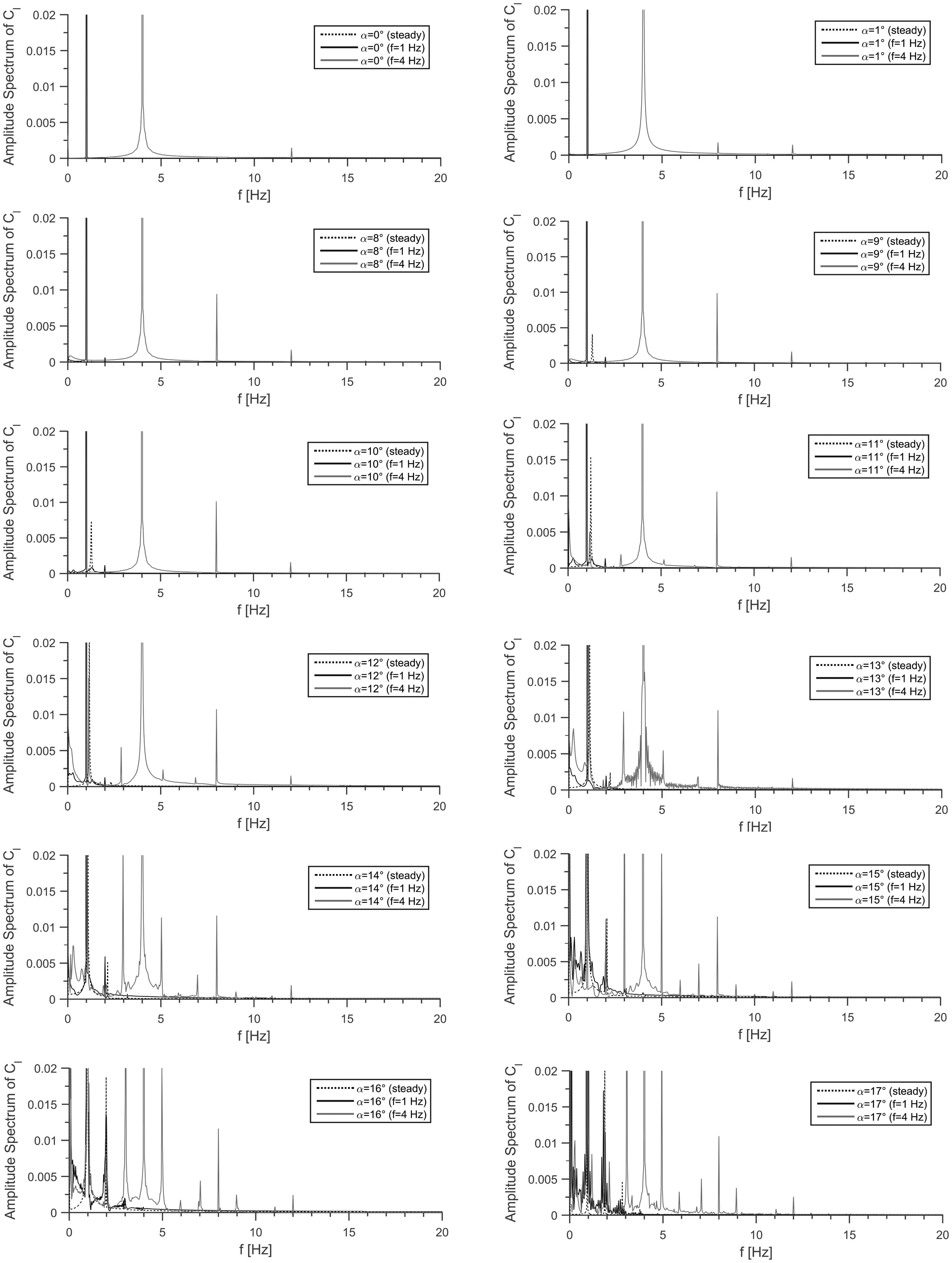
Amplitude spectrum of lift coefficients for f = 1 Hz and f = 4 Hz oscillations at α0 = 0° to 21°.
At steady airfoil, the amplitude spectrum of lift coefficient does not show any peak until the angle of attack of 8° (Figure 19). At 8° angle of attack, a peak of very low amplitude is observed at a frequency of f = 1.28 Hz (Strouhal number of St = fc/U∞ = 0.876 30 ). A maximum vortex shedding frequency of f = 1.3 Hz is observed at α0 = 9° (Figure 19) whose frequency amplitude can also be observed as dashed lines in Figure 20 at 9° angle of attack.
The frequency spectrum from 19° to 60° mean angles of attack reveals only a denser and higher amplitude low frequency spectrum as can be observed from Figures 20 and 21. It is known that for larger angles of attack, the frequency becomes smaller which implies that the shedding period of Karman vortices are longer. In literature, it is also denoted that as the shedding period increases with angle of attack, the more K–H vortices are amalgamated to form one Karman vortex.30,40,41

Amplitude spectrum of lift coefficients for f = 1 Hz and f = 4 Hz oscillations at α0 = 40° and 60°.
Conclusion
The numerical simulation of sinusoidally pitching NACA 0012 airfoil at Re = 1000 is performed at small amplitude oscillation of 1°. The computations are performed for mean angles of attack ranging from 0° to 60° and for pitching frequencies of 1 Hz and 4 Hz. Even at this small amplitude of oscillations, it is observed that the pitching frequency does not only alter the aerodynamic force coefficients but also the vortex shedding patterns of the airfoil. A periodic vortex shedding is observed above α0 = 8° for steady airfoil case and α0 = 10° for f = 4 Hz pitching airfoil which has created a delay effect on the unsteady wake formation at the downstream of the airfoil. In contrast, the periodic vortex shedding can be visualized for all angles of attack of the NACA 0012 airfoil oscillating at f = 1 Hz frequency.
A period doubling is observed in a sinusoidal form only for the drag coefficient at zero mean angle of attack at both oscillation frequencies. Negative instantaneous drag coefficients (thrust) are observed at f = 4 Hz pitching oscillation from mean angle of attack of 3° to 37°, but there is no thrust observation at f = 1 Hz oscillation for all angles of attack investigated.
Footnotes
Declaration of conflicting interests
The author(s) declared no potential conflicts of interest with respect to the research, authorship, and/or publication of this article.
Funding
The author(s) disclosed receipt of the following financial support for the research, authorship, and/or publication of this article: This work is supported by TUBITAK with project number 116M273.