
Abstract
Inspired by talon of a predator bird, this paper presents a quadrotor with two 2- Degree of Freedoms (DOFs) compliant manipulators which could mimic bird perching and grasping. The symmetric configuration of the manipulators causes minimum shift in center of gravity and a minimum disturbance to the angular momentum of the platform during grasping and perching maneuvers. Thus, the dynamics of the manipulator is independent to that of the platform. Moreover, a compliant end-effector is introduced to decouple the dynamics of the unmanned aerial vehicles from the force interaction with the environment or target objects. Therefore, aerial manipulation problem is significantly simplified due to the minimum amount of disturbance among components. In addition, the manipulators could function as the landing gear, which allows larger work envelope, weight saving and less landing impact. It also has the potential to achieve a bird-like “perch and watch” to increase the endurance of unmanned aerial vehicles in missions that involve extended endurance.
Introduction
The capability of unmanned aerial vehicles (UAVs) can be expanded radically with aerial manipulators. They have enormous potential in building infrastructure, disaster response, parcel delivery and many other applications, due to their ability to complete difficult tasks such as aerial grasping, capturing and assembling. However, UAVs, especially multirotor drones, suffer from very low endurance as significant amount of energy is required to generate lift. If a multirotor could behave like a bird, which not only grasped with its claw (aerial manipulation) but also achieved “perch and watch” maneuver where sustained observation is required, endurance could be increased significantly. Current design of aerial manipulators usually focuses on one of these two aspects, namely either perching or grasping. They are either only manipulators which are usually limited by a separated landing gear, or an only perching mechanism which could be used to perch on a specific surface type, thus losing the flexibility as a manipulator. Given manipulation itself is a challenging task, it is more complicated when combined with an aerial platform as well as interacting with the environment. Related work about aerial manipulator and specific perching mechanism will be addressed separately as follows.
Manipulator
Researchers have developed many types of manipulators for various aerial vehicles. The examples discussed in this paper are categorized by aerial platform and their manipulator types. With traditional helicopter platforms, there are passive manipulators, 1 industrial robotic arms 2 and mechanical hands. 3 With ducted-fan UAVs, there are parallel manipulators.4,5 On the multirotor drone, which is the most popular research platform due to its mechanical simplicity and reliability, there are single and dual serial manipulators with different DOFs,6–14 parallel manipulators,15–17 vacuum suction manipulators, 18 humanoid arms 19 and magnetic manipulator. 20
Most of these manipulators come from or evolve from industrial manipulators. These manipulators focus on the grasping task, and usually cannot be used as landing gears for perching directly. In fact, their work envelope is typically constrained by landing gears. A manipulator which doubles as a set of landing gear would make the quadrotor behave more like the real flying master in nature. A few issues which typically limit the manipulator acting as landing gear are:
The manipulators are not strong enough as landing gear. Aerial platforms can be massive, and manipulators usually consist of lightweight structure. The manipulators. configurations are not stable or suitable for landing gear. It is challenging to have center of gravity (CG) of platform falling inside the support area.
Another critical issue in aerial manipulation is the dynamics coupling between the manipulator and aerial platform. The CG shift, inertia and the angular momentum change of the platform affect the stability of the platform significantly. There are two approaches to handle this problem. Some researchers modeled the quadrotor platform and manipulators as one system such as in references.7–14 Other researchers either use passive manipulators or choose to control the aerial platform and manipulator separately. Thus, the airborne platform controller treats the manipulator as a disturbance and manipulator controller handles the platform error as uncertainty. With the second approach, a manipulator which has minimal effect on the aerial platform is desirable. The second approach is also the method adopted in this paper.
Perching mechanism
Regarding perching mechanism for quadrotors, there are passive biomimetic mechanism, 21 active perching mechanism, 22 a dry adhesive mechanism 23 and vacuum suction.24,25 The biomimetic manipulator used in Doyle et al. 21 can achieve perching without consuming energy. Vacuum suction24,25 is a practical solution for perching and grasping in many ways. The perching mechanisms mentioned above are all pragmatic solutions under certain constrained environment. The only unsatisfied part is that they lack the manipulator.h adaptability.
Contribution
This paper makes three key contributions in aerial manipulation for quadrotor type UAV. Firstly, a compact prototype of quadrotor with symmetric manipulators also as landing gear is designed, built and tested. The benefits of this configuration is larger work envelope and weight saving. Secondly, implementation of symmetric dual manipulators with compliant end-effector is described in details. The symmetric configuration and compliant end-effector minimize the disturbance generated by manipulators as well as when interacting with the environment. Finally, a control architecture and strategy is introduced for perching and grasping. Although our frame is customized, the setup could be easily transferred to other quadrotor platforms. Overall, it provides a simple and feasible configuration aerial perching and grasping with quadrotor type UAV.
Organization of this paper
The remainder of this paper is organized as follows: the next section presents the principles that guide the design of the system. Section “Design implementation” discussed the detailed design of the aerial platform, manipulator and the entire system setup. Section “Experimental results” shows the platform performance test setups, results and discussion. The final section provides the summary and future work.
Design consideration
The balance between weight and power is one of the most important considerations in both aerial platform and manipulator design. Thus, there is less impact on the system when landing and less load demand when perching. Furthermore, the limited payload capacity can be utilized for actual payload and battery instead of heavy manipulators.
Aerial manipulators. design should also take CG shift and angular momentum change when manipulating into consideration. Moreover, the stability of the dual manipulators serving as landing gears should also be discussed.
Disturbance induced by CG shift
When operating target object with manipulators, it is almost inevitable to have shift in CG position. The offset CG away from the vertical body axis will generate a rotation moment which will influence the aerial vehiclece attitude significantly. Thus, it is beneficial to minimize CG shift from the vertical vehicle reference axis when operating. A dual manipulator configuration is chosen because of its effectiveness in keeping the payload CG in line with the vertical vehicle reference axis, as illustrated in Figure 1. M is the torque generated by CG shift.

Aerial platform inclination induced by CG shift.
Disturbance induced by angular momentum change
When a manipulator moves at a certain speed, it has a certain angular velocity. An asymmetrical manipulator will cause the aerial platform to rotate because the sum of angular momentum is non-zero. Again, the symmetry in the dual manipulator can effectively eliminate this disturbance as shown in Figure 2, where w1 is equal to w2 (w1, w2 and w are the angular velocities of the left manipulator, right manipulator and the whole platform).

Aerial platform inclination induced by angular momentum.
Landing stability
The manipulator could also act as landing gear when it is not used for perching. It should be able to buffer the landing impact as well as maintain landing stability. The idea is to let the CG of the whole system fall in the support area provided by manipulators under extreme landing situations. An example of such landing situation is depicted in Figure 3, where the propeller guard comes into contact with the ground. Thus, the entire system will have the ability to recover to the original stable state by taking advantage of the gravity. In the X-axis direction, there is plenty of margin for CG as shown in Figure 3(a), while in the Y-axis direction, it is easier to fall over due to the support area being relatively small as shown in Figure 3(b).

Return to stable position under extreme condition: (a) Return to stable position in X axis direction. (b) Return to stable position in Y axis direction.
End-effector
End-effector is a crucial part of an aerial manipulator. A rigid end-effector in contact with a rigid environment or rigid object can be a very complicated problem. Usually, the controller needs to incorporate the dynamics of the manipulator, friction in the drive systems, contact stiffness, contact geometry, etc. Adding a compliance element in the manipulator will simplify the problem. The compliance in the end-effector helps decouple the dynamics of the aerial platform from the environment or target objects. The damping effect provided by the compliance element could help reduce the oscillation caused by interaction force periodically imposed on the aerial platform. The downside of introducing compliance element into the system is that it lowers position accuracy of manipulator.
Design implementation
By incorporating all design considerations together, we developed a prototype as shown in Figure 4. The detailed implementation will be addressed in separate subsections. The next section discusses the detail design of the UAV platform itself. Section “Manipulator” presents the compliant of two 2-DOFs manipulators. Section “Control system architecture” presents the control flow of the whole system.
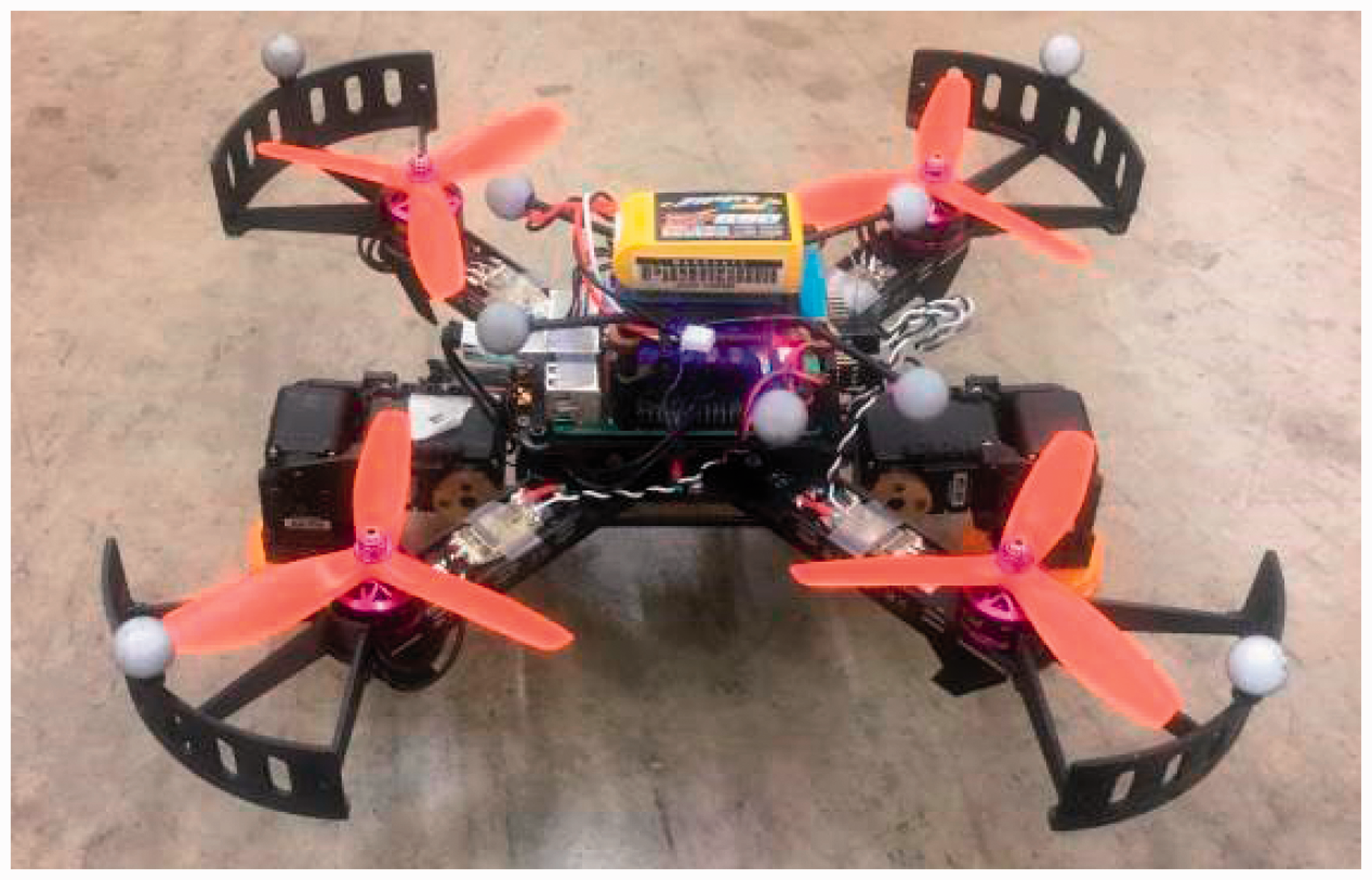
Designed prototype.
Aerial platform
As discussed in the Section “Design consideration”, a lightweight but powerful aerial platform is desirable. Inspired by the first-person-view (FPV) racing quadrotor, we customized a 250-sized quadrotor (250 mm motor center to motor center). FPV quadrotors are typically equipped with motors designed for aggressive maneuvers. These motors have a high-power density and power-to-weight ratio. The continuous power-to-weight ratio could be as high as 8 kW/kg with 3S battery and 5-inch propeller for a 33.5 g brushless motor.
The final selection for the aerial platform is listed in Table 1. The maximum thrust generated by one motor is around 6.32 N (645 gf) at the maximum speed of 19,950 r/min. As shown in Table 1, the whole platform including manipulator is 1085 g. The maximum thrust-to-weight ratio of the entire platform is 2.38, which provides sufficient load capacity.
Main components and weight.

Manipulator
The manipulator needs to be lightweight, strong and compliant as discussed in the Section “Design consideration”. In our prototype, as shown in Figure 5, a symmetric configuration is adopted. The manipulator frame connected to the aerial platform is made of 3 mm medium density fiberboard, which is rigid and resilient. All the linkage parts of the manipulator’s arm are three-dimensional (3D)-printed ABS material (HobbyKing ABS filament 1.75 mm). Dynamixel AX-12A servos are selected as main actuators of the manipulators due to the high torque and relatively low cost. They also provide position and torque feedback which is crucial for the manipulation control algorithm. The dimension of the links of the manipulators is determined by mainly two factors, namely the load capacity of the servo and the operation space requirement. The links need to be kept as short as possible to ensure higher load capacity. They also need to be sufficiently long to satisfy the operation space requirement. The details of the manipulator.i dimensions are shown in Table 2.

Different operating modes.
Specification of the manipulator.

As shown in Figure 6, the manipulator has several operating modes for perching, grasping and landing. Mode 1 is the normal landing configuration mode. The compliant end-effector could absorb the impact during landing. Mode 2 is the arm manipulating configuration mode for a larger target such as a plank of wood. Mode 3 is the arm manipulating configuration mode for a smaller target. The end-effectors meet and form a closed loop to ensure the target object not to fall off. Mode 4 is the arm clamp mode and it creates the largest target envelope. Mode 5 is the end-effector pinching mode. It is used for handling delicate and small target or perching. In Mode 6, the end-effectors are positioned above the propellers, which shows the manipulator has the potential to uphold a target. All these working modes facilitate the manipulators to adapt to a different envelope of the target object or perching location. Note that the manipulator is not limited to the modes described above. They are presented here to demonstrate some possible ways to work with the current configuration.

Components of the manipulator.
End-effector
End-effector adds compliance element into the manipulators. Current availability of 3D-printed flexible material makes it much easier and cheaper to customize compliant parts. By adjusting the infill rate and the filament support structure in 3D-printed configuration, customized stiffness of flexible elements could be achieved.
Given the exploratory nature and complexity of the contact dynamics, a simple experimental iterative method is adapted to determine the stiffness of the material instead of an analytical approach. Infill rate ranging from 20% to 100% were tested at every increment of 10%. Finally, the 30% infill rate is selected for its overall performance as manipulator and landing gear due to the desirable deformation under specific load and damping effect in the landing tests. The chosen end-effector design consists of four parts, an upper pad, a lower pad, springs and anti-slippery cloth as shown in Figure 7. The upper pad and lower pad are the main damping parts. The springs are intended to lower the stiffness of the end-effector. The anti-slippery cloth is used to increase the friction coefficient of the contact area. The upper pad and lower pad are made of a 3D-printed flexible material (HobbyKing 3D-Printer Filament 1.75 mm Flexible). The shape of the end-effector is intended to operate on both flat and curved surfaces.

Details of the end-effector.
Control system architecture
As shown in Figure 8, our prototype consists of PIXHAWK 26 flight controller which handles all low-level control of the aerial platform, an onboard computer (Raspberry Pi 3 model B) which processes all high-level control commands including trajectory following and manipulation algorithm. A pair of 900 MHz telemetry radios are used to monitor the states of the UAV such as battery level, flight mode, etc. Accurate position and attitude feedback of both quadrotor and target are provided by Optitrack motion capture system and sent to the onboard computer through Wi-Fi. Manipulatorny position and torque feedback are sent directly to the onboard computer by serial connection. The gray blocks in Figure 8 indicate that these components are on the aerial platform.

Structure of the system (gray block components are onboard vehicle).
Two separated controllers are adopted in this paper. The quadrotor flight controller follows traditional cascaded architecture and manipulator controller is essentially a servo position controller accompanied with torque feedback. With torque feedback, manipulator controller can make sure that at the current position a moderate torque is applied on target and also protect the servo from overload. As shown in Figure 9, the quadrotor is controlled to hover at first. After a specific time, it was commanded to hover right above the target. Then if the position error in X and Y directions is within the threshold, quadrotor begins to descend. When the quadrotor reached pre-planned position, check the position error in X, Y, Z directions and also the velocity of the quadrotor. If they are within the threshold, then the manipulators will be engaged. Once the manipulator is engaged, it follows a pre-planned trajectory. When manipulator reached the desired position, it will double check torque; if it is within the threshold, quadrotor will go to the next stage. If the torque is not within the accepted area, usually it means a failed attempt, the quadrotor should ascend to hover state. Depending on the situation, the quadrotor either disarms motors for perching or ascends for grasping. Note that right now all the commands sent to servos to engage a successful grasping or perching need to be determined by the manipulator experiment beforehand.

Control strategy diagram.
Experimental results
We conducted several experiments to evaluate the feasibility of our current prototype. As shown in Figure 10, the first set of experiments was conducted to assess the ability of the manipulator at handling objects of different shapes. The manipulator successfully grasped the same wood plank in two different modes. In addition, it was shown that the end-effector could adapt to objects with both flat and curved surfaces.

Grasping objects with different shapes.

Grasping and dropping a milk carton into a target container.
The system carried out a fully autonomous mission in the second experiment as shown in Figure 11. The first objective of the mission was to pick up and hold a milk carton weighing 200 g placed on a tripod. The aerial platform then carried the carton to a designated position over a container placed on the ground. Once the aerial platform arrived at target position, the manipulators would then release the milk carton into the container. This experiment demonstrated the potential of the aerial manipulator in real-world applications. The experiment also proved that the manipulator was able to carry out the operating task without introducing significant disturbances to the platform. During the autonomous mission, position controller of the aerial platform treated the manipulator and the weight of the target object as disturbances.
The third experiment is shown in Figure 13. The aerial platform conducted a series of maneuvers to perch on a steel pipe. A steel cylindrical pipe was clamped at both ends to mimic a tree branch in an outdoor environment. The position of the steel pipe was known in advance by Optitrack system. This test demonstrated that the current setup has the potential to achieve “perch and watch” maneuver, which could improve the endurance of UAVs significantly. Since the manipulator consumed only 0.5 A to hold position when perching on the pipe, the power consumption was considerably smaller compared to 15 A when hovering with motors. The aerial platform also successfully took off from the steel pipe safely.
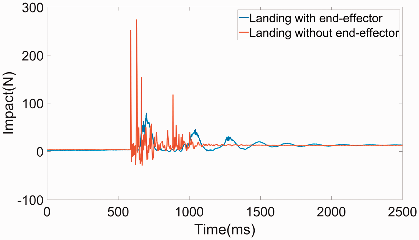
Landing impact test.
The fourth experiment was the landing impact test. A landing impact was simulated by dropping the vehicle from a height of 50 mm, which was determined by acceleration due to gravity to achieve a descent rate of 1 m/s at impact. The land impact with and without the compliant end-effector on the aerial platform was measured separately. The impact is measured with ATI mini45 six-axis load cell, and all data are acquired with NI DAQ USB-6251. The peak landing impact decreases from 274 N without any damping to 79 N with compliant end-effector on the manipulator as shown in Figure 12. It proves that the damping effect of the manipulator as landing gear.

Perch on a fixed steel cylindrical pipe.
The fifth experiment was a disturbance test. The manipulator was mounted on the ATI nano25 six-axis load cell and moving from one end-point to the other end-point repeatedly at the speed of 90°/s with only one arm moving and both arms moving simultaneously. The most notable disturbance is the moment generated by the moving manipulators. As shown in Figure 14, as the servo torque counters each other when moving two manipulators at the same time, the moment generated is significantly smaller than moving one manipulator, which is the configuration of the most aerial manipulator.

Disturbance generated by the manipulator.
The final experiment was designed to verify the influence of the manipulator on the aerial platform was small when the manipulator was operating. The manipulator should add as little disturbance as possible to the aerial platform. During this experiment, the manipulator servos were given a command speed of 90°/s to open the manipulator. A motion capture system was used to log the position of the aerial platform. As shown in Figure 15, the platform took off manually (at 25 s) and then switched to position hold mode (at 52 s). It took about 20 s before the platform reached the target position and a target altitude of 1.2 m (at 80 s). Then the whole platform tied to hold the desired target position at the origin of the world coordinate with 1.2 m altitude. During the position holding process, the manipulator cycled between Mode 1 and Mode 5 for around 40 s before the aerial platform exited the position hold mode and landed. The influence of the manipulator was evaluated by observing the position error during position hold mode. The maximum offset from desired position in X and Y axes was less than 25 mm and the offset in the Z axis was kept under 20 mm. The results indicated that the influence on the aerial platform introduced by manipulator operation was minimal.

Position hold error when operating manipulator while hovering.
Conclusion and future work
This paper affirms the feasibility for a quadrotor with two 2-DOFs compliant manipulators to have perching and grasping capability. The dual 2-DOF manipulators could adapt to many different types of target. The symmetry configuration of the manipulator has little influence on the aerial platform and adding compliance element in the end-effector helps to decouple the dynamics of the manipulator with target or environment. They both significantly simplify the aerial grasping or perching task. Furthermore, the dual functional manipulator also enables the platform to mimic a bird-like “perch and watch” maneuver, so that observation endurance can be improved.
For future work, the flight controller will be rewritten to take the manipulator,y behavior into consideration. The effect of propeller wash on the target object should also be considered in the future to allow better overall performance. Finally, by adding an extra DOF to each manipulator arm, the aerial platform can potentially achieve walking on the ground to maneuver in environment where flying is prohibited.
Footnotes
Declaration of conflicting interests
The author(s) declared no potential conflicts of interest with respect to the research, authorship, and/or publication of this article.
Funding
The author(s) received no financial support for the research, authorship, and/or publication of this article.