
Abstract
Teleoperation of unmanned aerial vehicles is hampered by communication delay, which causes feedback from command inputs to take considerable time to be displayed to the operator. For an international internet connection, round trip latencies can reach 500 ms. The satellite connections used for military unmanned aerial vehicles can have latencies in the order of seconds. This delay presents a substantial control problem, which has been solved in the past by control abstraction (instead of “roll left” the aircraft might be instructed “go to these coordinates”). Manual control remains difficult. This study borrows the client-side prediction concept from multiplayer video games to attempt to address the control delay to allow manual control. An estimate of the change in the vehicle state due to the commands that are yet to affect the feedback is computed and then the feedback that the pilot receives is modified to reflect this predicted change. Because of this change, the pilot can see immediately the effect of the control inputs. This study has explored the concept and built a prototype system functional in real time for flight testing with qualitative results presented.
Introduction
Unmanned aerial vehicles (UAVs) are seeing widespread growth in many existing and new applications. Presently, UAVs are often operated within the line of sight (LoS), where the control delays come primarily from the control radio system in use. Entry level hobby transmitters commonly achieve latencies in the order of 20–30 ms. Advanced hobby radio systems boast ranges of 60 km.1–6
When operating via a local video link, camera latencies range from 40 ms for the fastest analog systems to hundreds of milliseconds for digital systems. Recently, hobby grade low latency digital video transmission has been introduced, with latencies below 50 ms achievable. Latency of wifi-based transmission systems can exceed 100 ms. Adoption has been low, likely due to cost and fragility.7–9
Some military UAVs are operated from thousands of kilometers away via encrypted satellite connection, which imposes a round trip delay in the order of seconds. Often the terminal flight phases are controlled from ground crews near the runway. Due to the short time scales on which the state of the vehicle can change during takeoff and landing, the latency presents difficulty in control. Outside of terminal flight phases, the latency is acceptable as maneuvers and disturbances occur on timescales much larger than the latency.10,11
Internet latency
The latency of packets sent over the internet varies depending on the source and destination. For example, latency from Australia to the US is measured at around 150 ms just to cross the Pacific Ocean. 12 Communications between an Australian and US location will include additional latency due to routing within each continent.
Control of a UAV over internet has been explored previously by the aerial international racing of unmanned systems (AIRUS) student project, of which the first author was a part. The impact of the latency on the control was found to be very significant, with even small latencies rendering a quadrotor UAV barely controllable. Previous work by team members has discussed the concept of a predictive aid and shown improvement in human control of a simulated system. 13
Operation with latency
In 1967, Ferrell and Sheridan 14 discussed the problem of teleoperation. Three main components of a remote operation system were described: a remote loop that acts to process tasks remotely (increasing the abstraction of the control); a supervisory loop that consists of the operator receiving information about the remote device’s environment and specifies new commands; and a local loop that represents the operator’s computer locally assisting (such as by modeling the remote system to present quasi-feedback). Increasing the command abstraction by allowing the remote loop to process the perceived environment and determine sub-tasks to achieve a higher level goal forms the majority of the systems proposed by Ferrell and Sheridan.
Effect of latency on pilots familiar with an aircraft type has been investigated by Lloyd, 15 who found that control latencies in a Cessna 172 N simulation of 240 ms were enough to produce measurable degradation of performance, while 1000 ms latency was found to be unsafe. Operation of multirotors with latency has been investigated by Abdulrahim et al., 16 who found in position hold modes that delays of 100 ms were enough for pilots to notice degradation in system performance. Latencies of 400–600 ms or more were rated intolerable by test pilots. Abdulrahim refers to angular-rate-tracking mode (the flight mode investigated in this paper) as likely to present additional difficulty when a latency is introduced as higher control bandwidth is required. Thurling and Greene 17 investigated the use of a predictive visual aid for controlling the pitch axis of a fixed wing UAV around an equilibrium condition with varying latency. Markers within a HUD were used to show a predicted vehicle state as an aid to test pilots, who were able to control the aircraft more effectively when the aid was shown.
Latency can also be present in manned air vehicles, and presents risk of dangerous pilot induced oscillations, especially in simulated faster responding aircraft such as fighters as compared to simulated slower responding aircraft like large transports. 18 Ricard 19 presented an extensive bibliography of early research into manual control with latency, much of which is focused on aerospace applications.
The operation of a robotic arm with delayed control is investigated by Bohren et al., 20 who presents an assisted teleoperation architecture. A virtual robotic arm with a control delay is used to perform part of an assembly task. The visualization of the scene is enhanced by displaying the user command overlayed on the robotic arm, as well as by estimating user intent. The user intent is estimated from the user inputs and the displayed scene that they are in response to, and then the user input is modified to try to effect the user intent in the real scene. With the assistance, test subjects showed substantial improvement in task completion time.
Latency in multiplayer videogames
Online videogames have previously undergone development similar to the proposed system. Bernier 21 detailed the progression of architectures, from a single server handling a number of clients that are entirely ignorant of the game mechanics to more modern configurations using client-side prediction and other more advanced routines. A number of the procedures detailed by Bernier are associated with foiling untrustworthy clients (cheaters) and it is noted that for military simulators, the clients are trusted.
The most basic feature discussed by Bernier is client-side prediction. In a dumb-client system with a network latency, the inputs from the client are sent to the server, which interprets how they change the game state, which is then sent back to the client. Movement of a player through an environment is given as a notable example where client-side prediction can be used. Instead of waiting for the server to acknowledge a movement command and update the game state, the client assumes that the command will be accepted by the server and processes the expected game state change by itself. The canonical version of the game state is handled by the server, so the client prediction may need to be retroactively altered. This may occur for example when the player input has an unexpected result due to another player’s input that has not had time to be transmitted to the client or due to game state information that is hidden from the client. With client-side prediction, the player perceives that their movement commands are being processed instantly, rather than with the round trip latency, and so their experience appears consistent regardless of latency in their connection.
Bernier claims that the success and longevity of a videogame requires a seamless multiplayer experience.
Flight controller modes
Quadrotor platforms are, in all practical cases, controlled via a digital control system. In these control systems, the operator commands particular flight variables, rather than controlling the motors and other actuators directly. The actuators used are the four (other numbers can be used but for simplicity only quadcopters are discussed) propellers, with the left/right, forward/back, and left/right diagonal pairs each being used to generate roll, pitch, and yaw moments, respectively.
Presently, the only widespread method of combating latency in UAV control is abstraction of the pilot’s controls (move to a GPS coordinate instruction replacing roll/pitch/yaw commands). With UAV technologies expecting to see substantial growth in both civilian and military sectors, the controllability of UAVs at long range (and hence with control latency) is an important area of development. Current systems are either short range and low latency or long range and high latency. The tried and tested client-side prediction concept from multiplayer videogames is a strong candidate for expanding the operability of UAVs at long range.
Proposed system overview
To combat latency, the client-side prediction concept is applied to a UAV. The adaptation to a UAV can be summarized as predicting and displaying the vehicle state at the time when the commands being given currently will arrive at the vehicle. The eventual goal is to implement the scheme on a micro (112 mm size) quadrotor flown in rate mode using a video feed from onboard as feedback. Rate mode means that the operator’s stick position maps to an angular rate command about all three axes, which is the most primitive mode, usually with only a single loop in the controller on each axis. The operator receives information about the vehicle’s state from the video feed, including the angular position from the image of the horizon.
Figure 1 shows the flow of commands and feedbacks around a time tn at the remote station. 2τ is the roundtrip latency (the one-way latencies have been assumed to be identical and equal to τ). A convenient choice for the origin of the time axis is

Flow of command and feedback.
At the control station at tn, the remote station has the feedback that is delayed by τ, but it can also see the commands that have already been sent. The commands between tn – 2τ and tn will arrive at the quad after the feedback at tn – 2τ, and prior to the command being given at tn and arriving at tn. This command information is then used to predict the change in vehicle state, and hence the feedback that the operator would expect to see if there was no delay.
The mathematics of the problem can be described more simply as: Given the system state and command inputs to be executed, predict the system state after those command inputs have been applied, which is a familiar problem from control theory with well-developed means of solution.
System block diagram
Figure 2 shows the suggested system, which is similar to the Smith predictor.22 The operator is modeled as determining a desired attitude, comparing that attitude to the feedback they are shown and then applying a controller to determine a command input. The compensator compares two simulated flight states, one of which is delayed by the round trip delay time and then augments the feedback by this amount. The remainder of the system is formed by the actual transmission delay and vehicle dynamics.

Block diagram with delay and compensator.
Because the implementation later in this paper deals with an angular rate controlled quadrotor, while the attitude feedback is an angular position from a video stream, some integrator blocks are included. These terms are shown for completeness and could be modified if a different control arrangement was used.
The diagram shown is for the one-dimensional case, where θ is any of the roll pitch or yaw axes. A real implementation will require propagation of these axes in three dimensions.
The compensator can be removed by setting Gest = 0, which gives the system with only the delay. The delayed system can be reduced to the typical system by setting τ = 0, effectively removing the delay. Using the fact that the compensator and delay can be removed by substituting terms, the closed loop transfer functions need only be found for the delay and compensator case and the others will be readily found from those results.
Output and reported output response to command derivation
First, the closed-loop transfer functions are found for the block diagram with the compensation system. For convenience, we define


The delay term in the numerator is unavoidable, as the input cannot reach the output without being subject to transmission delay (and a negative delay is infeasible without predicting c(s) a short time in advance).
The disturbance response can also be found
Interpretation
The transfer functions for the compensated system can be used to find the delayed system and undelayed system for comparison. The control response transfer functions are shown in Table 1 and the disturbance response transfer functions in Table 2. With A(s) highlighted in green and delay terms highlighted in red.
Transfer functions for the control response.

Transfer functions for the disturbance response.

The introduction of the delay causes a delay term in the numerator of the command response and the counteraction to the disturbance.
The delay term in the numerator is caused by the forward latency for the command response and by disturbances needing to be observed and then responded to for the disturbance response. Addressing these delay terms is beyond the scope of this paper.
A delay term is also seen in the denominator. This term is caused by the operator being unable to immediately see the feedback from their inputs.
The introduction of the delay compensator modifies the term in the denominator. The term A(s), highlighted in green, still contains the delay term as the feedback from the vehicle is incorporated. If a suitably accurate estimate of the vehicle dynamics Gest(s) is known, then the term in the denominator becomes approximately equal to the undelayed denominator. The compensator acts to provide feedback that shows immediately the effect of the command inputs, removing the effect of the delay from the denominator.
The change that the compensator brings to the denominator makes the transfer functions much more similar to the no delay case. The command response is affected only by the forward latency, which delays the response but otherwise does not affect its behavior. The disturbance response is improved by the compensator, but it will still take at least the roundtrip latency before the pilot begins to correct disturbances.
Estimation error
If the vehicle attitude is estimated by integrating a model, which provides the vehicle attitude rate, then


Only errors in the model that manifest between tn – 2τ and tn form part of the displayed system state. Importantly, the error does not accumulate with time and large errors (such as from disturbances or rapid motions where model errors are amplified) will only manifest for the delay time. Also, so long as the latency 2τ is small, the error in the displayed information is minimal. If a dead reckoning approach is used, then the error will increase by roughly a factor of tn/2τ, and will hence grow with time.
System identification
To predict the motion of the vehicle, a dynamic model is needed.
For the quadrotor vehicles considered in this paper, the dynamics of the three rotational axes were assumed to be independent of each other and the flight condition (speed, altitude, throttle setting). This assumption is valid only in rate mode.
The development of high rate flight data recording 23 allows system identification by measurement rather than modeling. Quadrotor models do exist, but model measurement was chosen due to the importance of accuracy to the specific hardware and software configuration. A large amount of vehicle geometry information and parameters would also be needed for a derived model approach, many of which are difficult to measure and quoted incorrectly by the manufacturer.
Obtaining a model
Finding a model of each axis from the recorded input and output data was achieved using the inbuilt tfest function in MATLAB. This function accepts one or more logs of system input/output data and returns a transfer function that closely maps the input data to the output data. The function works by creating an initial guess and then iterating to minimize the error in the transfer function. 24
Identified system
For the 112 mm quadrotor used, eight flight logs were used to generate a system model. The procedure was validated by generating eight models with a log each excluded and verifying that the models remained valid on the excluded log. Bode plots of the system model generated from all eight logs are shown in Figure 3. The models map angular rate command to the angular rate.

The models generated for the 112 mm quadrotor.
Augmenting the feedback
With the change in vehicle attitude predicted, the feedback can be augmented to reflect this prediction. The video is first undistorted to remove fisheye effects from the camera lens, and then warped so that the horizon (and other objects far from the camera) appears to move immediately with operator input.
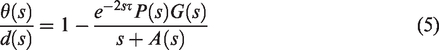
Figure 4 shows an example of image warping for a prediction of rolling. In this example, the feedback shows the quadrotor in a near-inverted attitude, but the command inputs that are yet to arrive will bring the quadrotor to nearly level, so the compensator warps the image such that the horizon appears level. Warping for the yaw and pitch axes is achieved by shifting the image left and right, with the camera field of view determining the rate (pixels per degree) of shifting.
Example of image warping. The image is warped to reflect the compensator predicting a 135° roll to the right.
Simulated predictive performance
Before implementing the compensator, it is desirable to estimate the predictive performance and to understand how the duration of the latency will affect the performance. The predicted position can be expressed in terms of the actual position and the error in the modeled system as


The accumulated error from the start of the flight is found by integrating the difference of the measured output and the output modeled from the measured input. The difference across a moving window is then taken to find the prediction errors throughout a flight log. The predictive performance was only measured on logs not used to generate the model used to assess performance (as a model derived from the flight log after a flight cannot be used to predict during that flight).
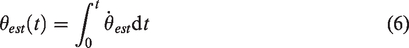
A histogram of the prediction errors was computed to visualize the performance. A histogram of the typical prediction errors on the roll axis with a 1 s delay is shown in Figure 5. The standard deviation of predictive errors with a 1 s delay for this flight is 1.1°, and most flights show similar distributions of errors, with no more than a couple of degrees standard deviation. A more thorough analysis of the simulated performance and variation in performance with latency can be found in Cox. 25 With predictive performance within a few degrees, the concept is now ready for implementation and proof of concept.
Histogram of predictive errors on the roll axis throughout a flight, for a delay time of 1 s.
Implementation
The latency compensation system was implemented on the 112 mm size quadrotor. The quadrotor was fitted with a fixed camera with analog transmission. The real-time implementation had three key parts:
Introduce an artificial latency Measure the command inputs and generate the prediction of the feedback’s change Receive and augment the video stream
The Node.js environment was chosen for implementation. Node.js is a javascript runtime, designed for internet connected applications and has event-based features. The event-based features are useful for running the simulation in real time, I/O in real time, and introducing delays. There is a large ecosystem of pre-existing libraries for a variety of tasks, including mathematical tasks, image processing and I/O. The Node.js environment will also be ideal for future work implementing on a real source of latency. Node.js is fast, but being an interpreted javascript environment it is not fast enough to run the image warping in real time.
OpenCV was used to perform the image undistortion and warping, which was faster than Node.js because it runs as precompiled C code.
The architecture for testing the compensator is shown in Figure 6. Regular flight uses Node.js as a passthrough to display video, to give a baseline. Flying with latency uses the Node.js environment to introduce latency to the system, and latency compensated flight uses Node.js to introduce latency and augment the feedback. All command and feedback passes through the Node.js environment.

The flight test architectures.
Figure 7 shows the simulation arrangement used. The simulation is indicated in blue, beginning from the start of the flight. The vehicle states in red are simulated and still in memory at tn. The simulated vehicle states at tn and tn – 2τ are compared to find the expected change in the feedback. A single propagation of the flight was used as it is difficult to guarantee that two simulations running side by side but separated in time will run with identical inputs, and hence may be prone to drift apart. In future work, input to the simulation from telemetry feedback may be necessary to ensure that the simulation does not drift from the true vehicle state. Because the quadrotor’s angular response does not vary with flight condition, this architecture is sufficient.

Simulation and computation of the predicted feedback.
Flight testing and results
The 112 mm quadrotor was flown without any latency, with latency and with compensated latency. Qualitative results are presented based on pilot remarks.
The test pilot did not have any remarks about abnormal flight behaviors when flown without latency. The size of the quadrotor meant that its position was quite susceptible to gusts.
Latencies of 500 ms and 1000 ms were tested. With a 500 ms latency, the test pilot struggled to maintain control. Early flights resulted in crashes. Later flights the test pilot was able to maintain flight, but only achieving the most basic maneuvers and tasks. Control was achieved by giving brief inputs and then waiting to observe the effect of those inputs before determining the next input. Controlled flight was not achieved with a 1000 ms delay.
Compensated latencies of 500 ms and 1000 ms were tested. The test pilot remarked immediately when flying with 500 ms of compensated latency that the aid allowed smooth control of the vehicle. With both 500 and 1000 ms of compensated latency, tasks such as following a fence line were achieved. Controlled flips in the roll and pitch axis were achieved. Figure 8 shows the pilot’s view at various points through a flip at 1000 ms latency. The flips highlighted that not accounting for the delays in the various command and feedback interfaces had an effect on the prediction. The compensator expected the video to show the vehicle rolling briefly before it did, so the horizon dipped from level as the quad was “catching up” to the pilot. This bug will be addressed in future flight testing.

Frames displayed by the compensator during a flip flown with 1000 ms latency. The issue introduced by the latency not accounted for can be seen in frames (f) and (g). Frames are labeled (a)–(h) chronologically. Frames on the left are taken from when the flip is commanded (vehicle remains level) while frames on the right are taken from when the vehicle executes the flip (horizon should appear to remain level, but does not because the compensated latency is slightly less than the true latency). The total time between the first and last frame is approximately 2 s.
Conclusion
The problem of teleoperation has been explored, and the client-side prediction model has been borrowed from multiplayer videogames to address the control latency problem in UAVs. The mathematical basis for the concepts viability has been explored and a scheme that does not suffer from drift has been found. The concept has been implemented and proof of concept achieved in flight testing. Future work may refine the system, explore systems where drift of intermediate states like airspeed could affect the system response or explore implementation with a real latency source (such as an internet connection).
Footnotes
Declaration of conflicting interests
The author(s) declared no potential conflicts of interest with respect to the research, authorship, and/or publication of this article.
Funding
The author(s) received no financial support for the research, authorship, and/or publication of this article.