
Abstract
This paper reports the development of an experimental airship drone powered by microwave as a precursor toward a large-scale airship drone for cargo transportation in mind under the collaboration with U.S. Federal Highway Administration and universities. Research work on a 2.2-m long airship drone powered by X-band microwave has provided sufficient data for the design and analysis for the operation of airship drone. A block of 16 rectenna array sheets of X-band was placed on each side of the airship drone (total 32 sheets) to collect and convert microwave power into direct current power for running the electrical propulsion system. The demonstration of the airship drone operation, powered only by microwave, was successfully performed inside the High Intensity Radiation Facility chamber located at NASA Langley Research Center. The data show the feasibility of practical use of microwave power for a transportation airship drone.
Introduction
Airships, known as lighter-than-air vehicles, are able to fly anywhere with minimal infrastructure to generate lift without the use of aerodynamic flow around wings and also to enable controlled, powered flight, providing long endurance at low energy consumption. 1 There is a growing interest in airships for long-range surveillance of military missions at-sea search and rescue, coastal surveying, fishery and marine mammal assessment studies, exploration, advertisement, sport, tourism, and recreation.2,3 There has been a fair amount of research in the area of airships in the past few decades, and recently, airships have been revisited as transportation systems for remote areas and heavy lift. Heavy-lift airships operating at low speeds can transport heavy loads with excellent fuel economy and therefore are considered to be an efficient and cost-effective transportation tool for point-to-point delivery of massive loads. 4 Thus, the development of new and sustainable airship transportation systems is necessary. The anticipated development of new transportation systems will require substantial future investments in entirely new energy sources and infrastructures, along with smart and intelligent transportation system networks. A green airship filled with a gas lighter than air has been proposed, which is electrically propelled to transport heavy cargo containers and people using the power collected by solar photo-voltaic or solar thermoelectric for daytime and microwave (MW) power for nighttime without the onboard power sources. 5 Prior to developing the green airship for heavy cargo transport system, this paper aims at demonstrating a microwave-powered airship drone filled with helium and by using X-band microwave without any onboard power source like battery. Figure 1 shows the concept of the microwave-powered airship. The airship has arrays of rectifying antenna, so-called rectenna, populated over the surface of its membrane in order to receive the transmitted wireless microwave power from ground power stations and feed the power of airship to propel and control it.
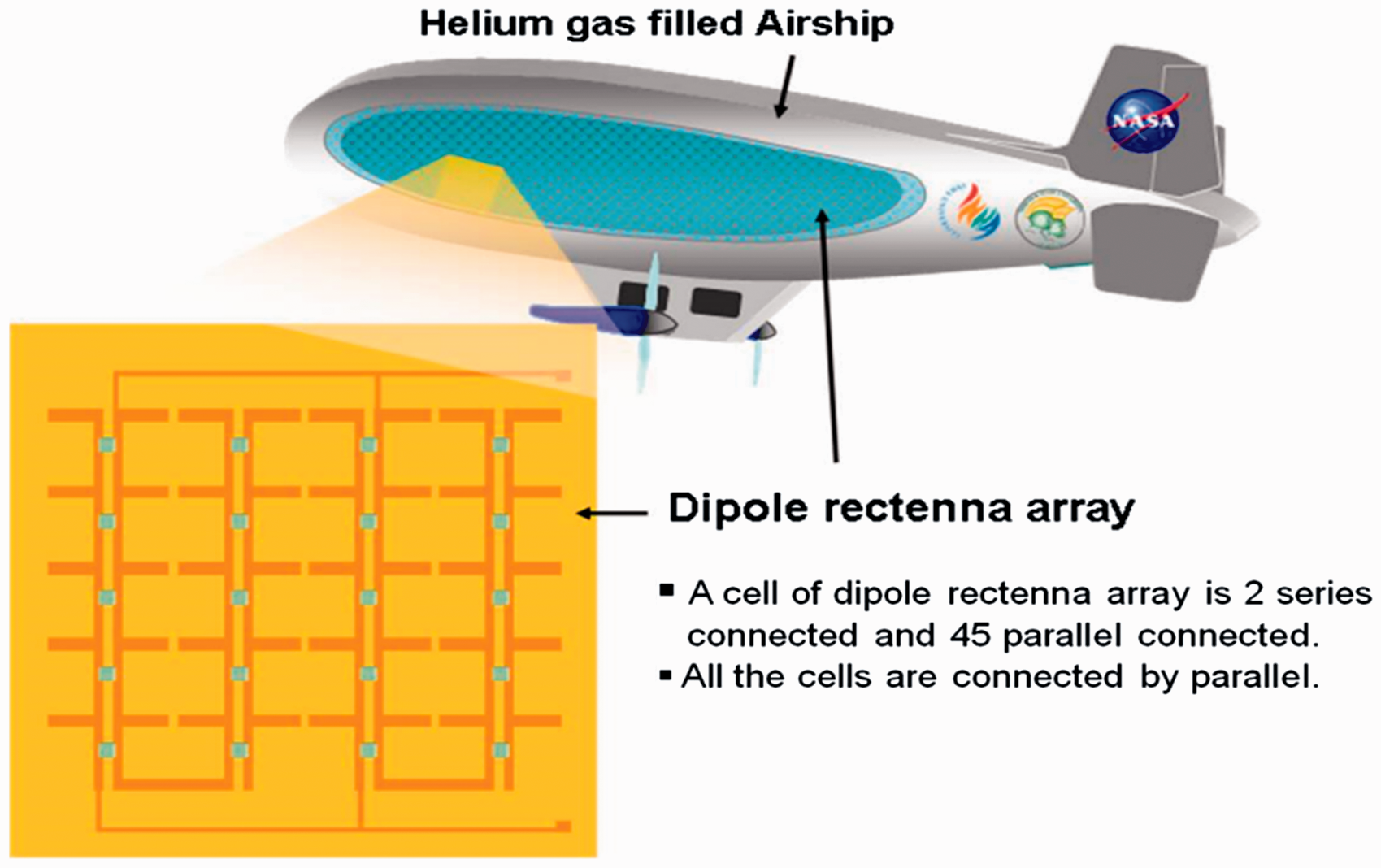
Concept of the microwave-powered airship drone.
One of key technologies in the microwave-powered airship is microwave power transmission (MPT). Theoretically, it does not require any energy storage devices such as a battery or hard-wired power-feeding system that would constrain the maneuverability of the airship. MPT technology using microwaves was developed in the 1960s by Brown et al. 6 His research demonstrated power transmission by electromagnetic waves and the rectification to direct current (DC) power. However, the fundamental idea for MPT was originally generated and performed by Tesla.7–9 Tesla used a coil that was connected to a 60 m tower, fed by a 1300 kW, and 150 kHz power source. Later, people realized that higher frequency microwaves were required for effectively focusing toward the power receiver. The first historical demonstration of MPT in the frequency range of 2.4–2.5 GHz for a helicopter was demonstrated by Brown 10 in 1964. A power conversion circuit, called a rectenna (rectifying antenna), was developed and used by Brown for the demonstration of the helicopter. Later, semiconductor diodes used in rectenna circuits were replaced by silicon Schottky diodes which raised the microwave-to-DC conversion efficiency from 40 to 80%. MPT was continually developed for the Solar Power satellite in 1978, for the Next Generation of Space Telescope in 1996.11,12 MPT is an attractive method by transmitting power for various sensors, devices, and moving vehicles, such as aerospace vehicles and robots. The MPT concept was proposed to control smart actuators13–15 for NASAs Next Generation Space Telescope. The use of MPT has been applied to smart actuators and recently extended to sensor data acquisition in medical applications.16–19 The microwave-driven MPT in integration with flexible solar panels on aero-vehicles was studied for a power generation system. 20 A continuous and daily operation airship at stratospheric altitudes was developed, in terms of power feed by photo-electric harvesting and optimal power unit. 21 The Energy Transmission toward High-altitude long endurance airship ExpeRiment was conducted by Kobe University and CRL in 1995. 22 The researchers transmitted a 2.45 GHz, 10 kW microwave to a flying model airplane having a total span of 2.9 m, a wingspan of 4.5 m, and flying at a distance longer than 150 m above the ground level. MPT is a proven technology; however, more studies are required to meet the requirements of specific applications such as integration of rectennas in the airship surface for optimized boundary layer air flow, design of rectenna elements for maximum density and conversion efficiency, design of robust rectenna dipole arrays, and design of rectennas for higher frequencies such as for a V-band or W-band microwave.
In this study, we demonstrate a wirelessly powered airship drone using X-band microwave whose size is 2.2 m long and filled with helium. A total of 32 rectenna array sheets were attached to the surface of the airship drone to convert the incident X-band microwave power into DC power collection for electric propulsion. This research provides quantitative data for designing an electrically propelled airship drone for transportation using the power collected by the arrays of microwave rectennas. The airship drone application using MPT can also be augmented with power harvested from solar energy during daytime operation.
MW-powered airship drone
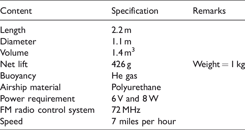
The feasibility test of a green airship drone is examined in this paper and focused on power transmission and ability to run the airship drone by microwave. A prototype of airship drone was designed and fabricated by TCOM. 23 Table 1 shows the specification of the airship. The airship drone is made with polyurethane, and the size is 2.2 m long and its diameter is 1.1 m. When its volume of 1.5 m3 is filled with helium gas, its weight is 1 kg and the net lifting force is 426 g. The airship drone has two motorized propellers for forward/backward operation and one propeller for lateral movement of the airship drone. The FM radio control system runs at 72 MHz, and the power requirement of all electrical systems of the airship drone is 7 V and 8 W. The electric motors are powered using an MPT system that will alleviate any onboard power generation systems. This concept of harvesting power wirelessly is envisioned as one of the best options to alleviate the complexity associated with hard-wired control circuitry in propulsion systems. This is accomplished through a rectifying antenna or “rectenna,” which consists of a dipole antenna with a diode connected across its elements. The diode rectifies the alternating current (AC) induced in the dipole antenna from the electromagnetic (EM) waves to create DC power.
Specification of airship drone.
Rectifying antenna
Principle, design, and fabrication of dipole rectenna have been well reported, and this is a brief explanation.15,16,24 The main components of dipole rectenna are a pair of metallic microstrip antenna and a rectifier that is composed of a Schottky barrier diode, inductor, and capacitor. Figure 2(a) shows the configuration of the single rectenna. The dipole rectenna has two metallic microstrips that are designed to tie up with at least a quarter of wavelength of the incident microwave band. The electrons in a conductor that are coupled with the H- and E-field of incident electromagnetic wave behave collectively as a wavy nature which is called a polariton. The collective charges in a wave form, the polariton, within the dipole strips are rectified through the Schottky diode so as to convert the microwaves to DC power. The power conversion of a dipole rectenna is governed by the performance of Schottky diode and the efficiency of dipole antenna. Generally, the power conversion efficiency of dipole rectenna is known to be higher than that of patch rectenna. The dipole rectenna for 10 GHz requires at least a 7.5 mm pole length for effective coupling.
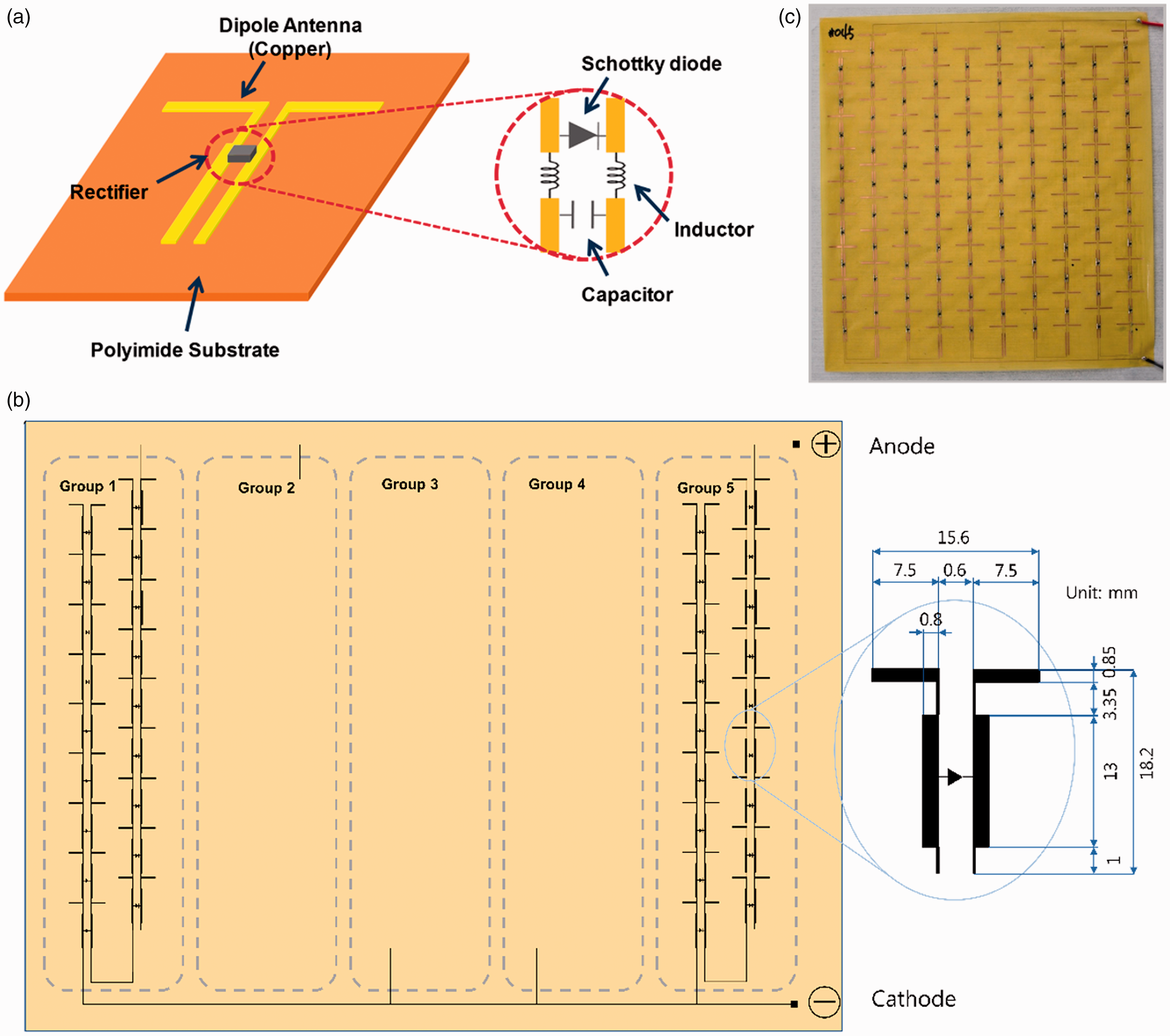
(a) Schematic of single dipole rectenna, (b) layout of the dipole rectenna array (90 rectennas), and (c) photograph of the fabricated rectenna array sheet.
Depending on the propulsion and control requirements of the airship drone, the converted power can be modulated for either low voltage/high current or high voltage/low current. To meet the power requirements of the airship drone, nine dipole elements were connected in series, and another nine dipole elements were connected in a row to increase the voltage output. These 18 dipole elements comprise a group of dipole rectennas, and this group was repeated four times in parallel along the positive and negative electrodes so as to increase the current output. Thus, totally, 90 dipole rectenna elements were placed in one sheet of dipole rectenna array. Figure 2(b) shows the layout of rectenna array sheet and the detailed dimension of the dipole rectenna element. Figure 2(c) illustrates its photograph. The forward voltage and current of the Schottky diode MA4E2054-1279 (MA-COM Technology Solutions Inc.) used are 0.25 V and 20 mA, respectively.
The dipole microstrip pattern of the developed rectenna array sheet was fabricated on a flexible circuit membrane (FCM) by using an etching process. The FCM is a 20-μm-thick polyimide membrane laminated with an 18-μm copper layer. A mask pattern for the dipole microstrip pattern was designed by computer. At first, a photoresist (PR) layer was coated on the copper side of the FCM and exposed to UV light through the mask pattern. After etching out the UV-exposed PR, the dipole microstrip pattern was obtained on the FCM. After the etching process, the Schottky diodes were soldered on the dipole microstrip pattern. The size of the rectenna array sheet is 18 × 19 cm2, and the weight of the rectenna array sheet for this demonstration is approximately 3 g, excluding the weight of circuit wiring (Table 2).
Specification of rectenna array sheet.

Fabricated rectenna array sheets were tested individually before being assembled on the airship drone. This test is to evaluate performance of each rectenna array sheet. The experiment was set up in a 1.2 m × 1.2 m × 2.4 m anechoic chamber, as shown in Figure 3 to measure the output voltage and current from each rectenna array sheet with a 200 W amplifier microwave power input. A microwave signal generator (HP-8672A) generates microwave signal, and an amplifier (VZX-6983-G5GLM, TWT, Varian) provides 200 W of microwave power at a frequency range of 7–18 GHz. The 200 W microwave power was delivered through a travelling wave tube waveguide connected to a Narda rectangular horn antenna and irradiated to the rectenna array sheets. The rectenna array sheets were installed inside of the anechoic chamber and tested at 100 cm far from the transmitting antenna with matching polarization. The rectenna array sheet was connected to a power measurement system located outside of the anechoic chamber, and the output voltage and current were measured at various frequencies. Figure 4 shows the voltage, current, and power outputs of the rectenna array sheet with respect to the frequency. The maximum voltage 4.2 V is shown at 10.5 GHz, and the maximum current is 200 mA. The maximum power output of 0.85 W at 10.4 GHz is obtained. The typical average output power for the single rectenna array sheet is 0.67 W (3.5 V, 190 mA) between 8.5 and 10.5 GHz.

The microwave anechoic chamber for the rectenna array sheet test: (a) outside of the chamber and (b) inside of the chamber with the fabricated rectenna array sheet.

Output of the fabricated rectenna array sheet: (a) voltage and (b) current.
The voltage and power requirement of the airship drone is 6 V and 8 W, powering two propellers for forward/backward operation and one propeller for lateral movement of the airship drone. This power requirement cannot be satisfied with single rectenna array sheet. Thus, it is natural to cluster the rectenna array sheets so as to increase power as well as voltage. As a preliminary test, a cluster of rectenna array sheets was made by connecting four rectenna array sheets in series as shown in Figure 5(a). The cluster of rectenna arrays was also tested in the anechoic chamber to measure the output power. The cluster of rectenna array sheets was located at a distance of 100 cm from the horn antenna in the microwave anechoic chamber, and the 200 W amplifier was used. Output voltage and current were measured in the frequency range of 7–11 GHz. The typical average output power was approximately 1.75 W (10 V and 175 mA) at 10.3 GHz.

(a) A cluster of four dipole rectenna array sheets connected in series and (b) four clusters of rectenna array sheets attached on one side of the airship, connected in parallel.
This output power is not enough to supply the required power for the airship drone, 6 V and 8 W. Thus, eight clusters of the rectenna array sheets (total 32 sheets) were attached on the both sides of the airship: four clusters of the rectenna array sheets were attached on one side of the airship, connected in parallel to increase the current output. Figure 5(b) shows four clusters of the rectenna array sheets attached on one side of the airship drone. On each side, four rectenna array sheets were connected in series as a cluster, and each cluster was connected in parallel. Four clusters of rectenna array sheets attached on one side were connected in parallel with the other side four clusters for producing high current. The power transmission of the airship test is illustrated in next section.
Experiment for MW-powered airship drone test
A High Intensity-Radiated Fields (HIRF) chamber located at NASA Langley Research Center was used for the microwave-powered airship drone demonstration. So far, the MW anechoic chamber was used to test the power transmission performance of the rectenna array sheets. This MW power transmission test in the anechoic chamber was tested under the assumption that MW is beamformed to the rectenna array sheets from the horn antenna so as to maximize the power transmission at the focused beam forming of MW. However, this assumption requires a tracking system of MW beam forming to feed MW to the moving airship drone. Thus, instead of the beamforming of MW, a reverberation chamber, so-called HIRF chamber, was used for the testing of the MPT prototype airship drone (see Figure 6(a)). This electromagnetically screened chamber with the size of 14.1 m × 6.9 m × 2.9 m is made of quarter inch thick steel walls, floor, and ceiling that minimally absorb MWs down to 120 dB in the 80 MHz to 18 GHz range. In the HIRF chamber, two rectangular horn antennas are installed to radiate MWs, and they are reflected on the inside surfaces of the reverberation chamber such that they fully fill the chamber. Figure 6(b) shows the outside of the HIRF chamber for equipment control. The low absorption of the metal causes the radiated fields to reflect off of the chamber surfaces numerous times, thus creating reverbed MW fields. Figure 7 shows the airship test configuration in the HIRF.
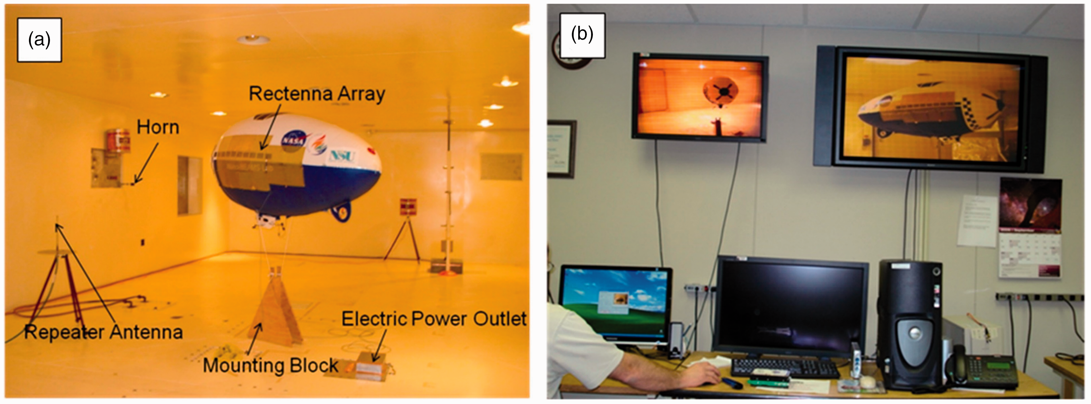
Experimental setup at NASA LaRC HIRF chamber: (a) inside of chamber and (b) outside of chamber for equipment control.
It is presumed that the rectenna array sheets on the airship drone will face the intensity of impinging waves averaged by every direction throughout the chamber. The power conversion for the rectenna array sheets in the HIRF chamber occurs either directly from the incident radiation or through reflection off the chamber walls. The airship drone was tested in stationary position in the HIRF chamber positioned at 6 m away from the horn and tethered on the mount in the chamber. At this scheme, the output power based on inputs, frequencies, and various incidence angles were measured. In the stationary test, the outputs of the rectenna sheet clusters from both sides of the airship drone were also individually measured. After finishing the measurement of incidence angle dependence and a flat condition test, the airship drone was positioned at the center of the chamber and removed all wires including tethered on the mount. It was necessary to balance the airship drone with additional weight inside of the consoles in order to float in the middle of chamber. After the chamber door is closed, the 200 W amplifier was turned on, and the RF control signal was used to maneuver the airship drone in free flight within the chamber. Since the weight of single rectenna array sheet is 3 g, the total weight of all rectenna sheets is 96 g. The weight of the original airship drone is 1.0 kg (volume = 1.4 m3) and its net lift is 0.43 kg. Therefore, the total weight of the airship drone for the given configuration is approximately 1.3 kg including rectenna array system, connection wire, and RF controller.
Experimental results
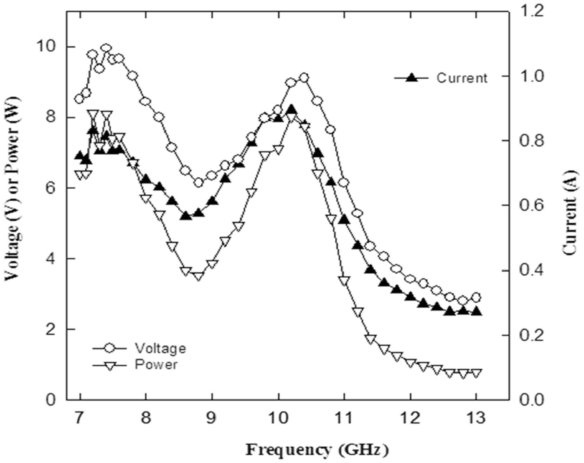
The MW power transmission of the rectenna array sheets attached on the airship drone was tested in the HIRF chamber. Figure 8 shows the output power from the rectenna array system (32 sheets) mounted on the airship drone for 7.2 and 10.2 GHz at various input power. The output power is nearly linear between 20 and 200 W of input power. In addition, 3–4% overall efficiency was found from the rectenna array system located 6 m far from the horn antenna. The output power measured in various frequencies from 7 to 13 GHz is shown in Figure 9. The output power significantly depends on the frequency and its maximum of 10.2 W is shown at 7.2 GHz and 8.0 W at 10.2 GHz. The peak voltage of the rectenna array system is nearly 10 V, close to the breakdown voltage of the Schottky diode. The highest current obtained is 895 mA at 10.2 GHz.
As mentioned earlier, one block of 16 rectenna array sheets were attached on one side (front) of the airship drone, and another block was attached on the other side (rear) as shown in Figure 7. The airship drone was located 6 m far from the horn with the center line of the horn aligned with the center of the rectenna array system. The output power was measured from the blocks of rectenna array sheets for both sides of the airship drone simultaneously. Figure 10 shows the results. The output power of the front side is 5.2 W while 5.0 W at rear side at 7.2 GHz. Total power output of the rectenna array sheets is sum of the front and rear sides. The output power of the rear side is 89–95% that of the front side. This result shows that there is power conversion from reflection off the chamber walls as well as from microwave power propagating through the airship drone. This interesting result requires further investigation since it will influence the design of the airship drone in terms of materials selection and airship drone dimensions.

Airship test configuration in the HIRF chamber at NASA LaRC.

Output power of the rectenna array system on the airship based on input power at 6 m distance from the horn.
Output power of the rectenna array system irradiated with 200 W amplifier microwave source.

Output power of front and rear rectenna array blocks at 6 m distance from the horn.
It is important to characterize the output power with respect to incident angles of microwave input power as determined by Lambert’s cosine law. Therefore, the airship drone was rotated around its vertical axis from 0° to 120° as shown in Figure 11. The output power varies from 10.2 W at 0° to 6.1 W at 90° (about 60%) as shown in Figure 11. These results will likely vary with the reflected beam intensity, the airship drone shape, and the rectenna sheet orientation.

Output power of the rectenna array system at various incidence angles.
In other condition, one may think “what would be happened on the output power of the rectenna if the airship drone has a leak which is called a flat condition?” Due to deformation of the airship drone surface, the exposure area will be reduced by the partially flat condition. This condition was tested by measuring the output power in a full filled He gas, and the output power of the rectenna was compared with a 30% flat condition as shown in Figure 12. This flat condition was measured by an equilibrium weight of He buoyancy force. As a result, the output power of the rectenna array system in the flat condition has less than 15% of the normal condition in frequency ranges of 9–10 GHz. In other frequency ranges, the output power in the flat condition is almost the same or even higher compared with the normal because the projected area may change its exposure area due to the flat condition. This result indicates that losing output power in the winkling condition is not necessary to be concerned due to a flat of the airship drone. In general, the previous result shows that microwave-empowered airship drone operation is quite promising feature based on the delivering power in various situation such as incidence angle, coupling features, flat conditions, and light weight operation due to no heavy battery.

Power output of the rectenna array system in a flat condition.
The maneuvering of the MW-powered airship drone was tested in the HIRF chamber. Supplementary information shows the video. The airship was successfully run in the chamber by MW power without battery. Table 3 shows the output performance of the MW-powered airship drone. The maximum output power of 8.3 W with the maximum voltage and current, 10 V, and 895 mA, respectively, was enough to run the airship. The maneuvering speed was 7 mph. The airship drone application using MPT can also be augmented with power harvested from solar energy during daytime operation.
Output performance of the MW-powered airship drone.

Conclusions
A 2.2-m airship drone was successfully operated in a reverberation chamber, powered exclusively by microwave transmitted from a 200 W amplifier. The 32 rectenna array sheets attached to the surface of the airship drone were used for powering the airship motors. This experiment also examined the operating performance at various incident angles, distances from the power source, and frequencies (7–13 GHz). Based on the measurement data, the output power of the side of the airship farthest from the transmission source was determined to be 80% of the directly exposed area when tested within the reverberation chamber. These results suggest practical use of rectenna array system as a power receiver for effective utilizing microwave energy for a transportation airship drone.
Footnotes
Declaration of conflicting interests
The author(s) declared no potential conflicts of interest with respect to the research, authorship, and/or publication of this article.
Funding
The author(s) disclosed receipt of the following financial support for the research, authorship and/or publication of this article: The author(s) received financial support from 2017 International Cooperation Program (GRDC-INHA IST-NASA Space Exploration Joint Research Center) through National Research Foundation of Korea (NRF-2017K1A4A3013662) for the research, authorship, and/or publication of this article.