
Abstract
This short paper introduces a new concept of rotor where the blades undergo a periodic surging motion in the rotor disk plane. It is shown that the unsteady actuation induces aerodynamic phenomenon that can enhance both rotor thrust and efficiency, depending on the amplitude and frequency of actuation. In particular, the increase in aerodynamic performance is found to correlate with the development of a large scale leading edge vortex. Accordingly, the optimal frequency is found to correlate with the formation time of this vortex.
Introduction
Unsteady airfoils can experience aerodynamic loads that are an order of magnitude larger than their steady counterparts. This was shown by Gursul and Ho
1
who experimentally measured the lift generated by a
Based on these findings, we introduce in this short paper a very simple, yet new concept of a micro air vehicle’s (MAV) rotor that aims at taking advantage of the aerodynamic mechanisms described above. The idea simply relies on operating the rotor at a rapidly varying rotation speed rather than at constant rotation speed. The term ‘surging rotor’ is employed to reflect the surging motion of the blade (in the rotor disk plane) in the reference frame associated with the mean rotation speed. The aerodynamic performance of the surging rotor is investigated through resolution of the Unsteady Reynolds Averaged Navier–Stokes (URANS) equations. The results presented for various surging amplitudes and frequencies under hovering conditions show that a surging rotor can outperform a conventional rotor in terms of both rotor thrust and efficiency.
Numerical setup
The surging rotor consists of two untwisted rectangular blades with 4% thickness flat plate profiles. The blades have an
The three-dimensional (3D) URANS equations are solved under their incompressible form using a finite volume method. 6 An overset grid approach is used that allows each blade mesh to move following prescribed, sinusoidal rotating motions within a stationary background mesh. The structured mesh consists of 4.7 million hexahedral cells (0.9 million for each blade mesh and 2.9 million for background mesh) enclosed within a parallepipedic domain of width 20R and height 50R (see Figure 1). The boundary conditions upstream and downstream of the rotor are implemented as pressure Dirichlet conditions, while the periphery of the parallepipedic domain is defined using a slip-wall condition. The blades are modelled as non-slip surfaces. Blade mesh is moved with a time step smaller than 1/720 time the rotating period. Both spatial and temporal discretizations are achieved using second-order schemes. Momentum and continuity equations are solved in an uncoupled manner using a predictor-corrector approach. Specifically, a colocated variable arrangement and a Rhie-and-Chow-type pressure–velocity coupling combined with a SIMPLE-type algorithm are used.7,8 Finally, the Spalart–Allmaras model 9 is employed for URANS turbulence closure with maximum y+ values on the order of 1.

Parallepipedic computational domain (a), overset blade mesh (b) and close-up view of the cross-sectional blade mesh (c).
Results for constant rotation speed cases are compared with available experimental data obtained at a Reynolds number of 60,000 (see Jardin et al.
10
for details on the experimental approach). Figure 2 shows that experimental data match the mean rotation torque

Furthermore, it was verified that the results are converged with respect to both spatial and temporal resolutions. Specifically, computations were conducted for both pitching and non-pitching rotors (15° mean pitch angle) with increased spatial and temporal resolutions (9 million cells and time step equal to 1/1440 time the rotating period). Results demonstrated that increased resolutions yielded variations in both time-averaged thrust and torque lower than 2% of the reference values (i.e. those obtained with the present setup). Further details on these convergence tests can be found in Jardin et al. 11
In what follows, the results will be analysed in terms of mean rotor thrust coefficient
Values of kR and σ in the range (0.2–1.1) and (0.4–0.8) are considered, respectively. ωr is set such that the Reynolds number at the tip of the blade is equal to
Results
Figure 3(a) shows the mean thrust coefficient
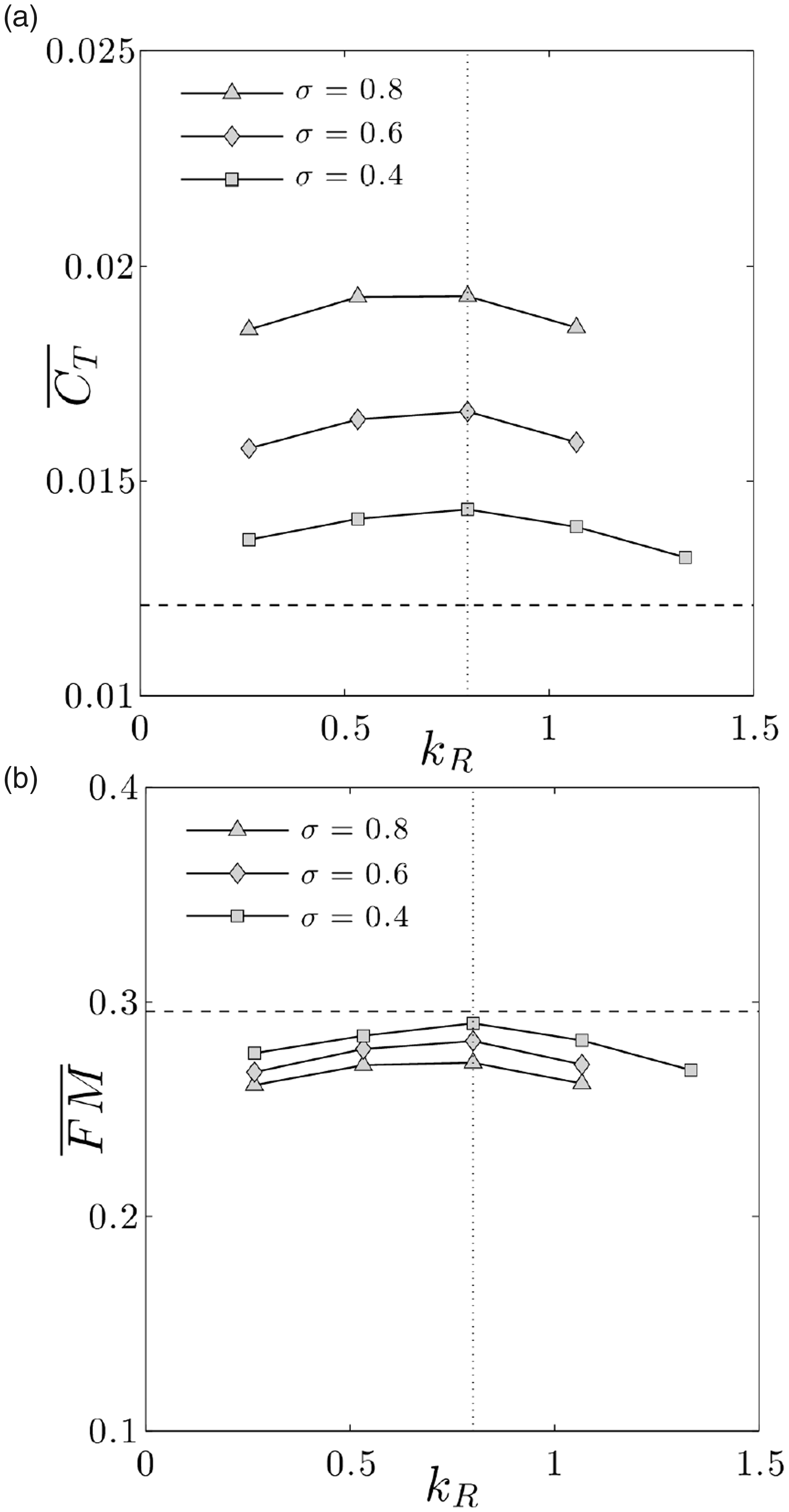
While a significant enhancement in lift is observed, Figure 3(b) shows that
Figure 4(a) and (b) displays similar results for a blade pitch angle of 20°. Similar conclusions than those raised for the 15° case can be made regarding the influence of surging amplitude and frequency on the aerodynamic performance of the rotor. However, it can be seen that in some specific cases, both

To quantify unsteady effects, the unsteady thrust coefficient CT is compared to its quasi-steady counterpart for the kR = 0.8 and

Unsteady (black line) and quasi-steady (black circles) thrust CT as a function of time (non-dimensionalized by the surging period) obtained for the kR = 0.8 and
This enhancement in instantaneous thrust can be correlated with the development of a large scale LEV that forms on the upper surface of the blade. Figure 6 shows a time sequence of the flow structure every 1/10th of the surging period. Vorticity contours and λ2-criterion isolines are shown in three cross-sections located at 1/4, 1/2 and 3/4 span. At t = 0, the instantaneous rotation speed is equal to the mean rotation speed. Inception of an LEV is observed in the vicinity of the leading edge, on the upper surface of the airfoil. This LEV then develops as the rotation speed increases, reaching a conical shape with apex at the blade root. At t = 0.3, while the LEV covers only a small portion of the blade at the 1/4 span location, it extends to the trailing edge at the 3/4 span location. At t = 0.4 and t = 0.5, the LEV at the 3/4 span location appears to lift off the surface and eventually sheds into the wake during the second half of the surging period. Further inboard (at 1/2 and 1/4 span), the LEV shedding also occurs but at slightly later times, i.e. around t = 0.7. Thus, at the 3/4 span location, shedding coincides with both the LEV interacting with the trailing edge and the blade decelerating to rotation speed below the mean rotation speed, that is, the surging period can be correlated with the formation time of the LEV, at the 3/4 span location. Conversely, further inboard, LEV shedding is triggered by blade deceleration before it can develop over the full chord and interact with the trailing edge. Here, the surging period is much smaller than the formation time of the LEV. Then, as the LEV is shed, another LEV forms at the leading edge of the airfoil. These observations show that the optimal surging frequency is the one that correlates with the formation time of the LEV around the 3/4 span, i.e. where most of the aerodynamic forces are generated. Formation of the LEV in this section corresponds to beneficial unsteady effects on lift and shedding corresponds to detrimental effects.

Cross-sectional spanwise vorticity contours and λ2-criterion isolines obtained for kR = 0.8 and
Overall, these results demonstrate that a surging rotor can outperform a conventional rotor in terms of both thrust and efficiency. In addition, because the performance enhancement is associated with a well-defined time scale, it is possible to design a blade that better takes advantage of the mechanisms at play. In particular, it was mentioned that the reduced frequency k(r) depends on the local radius along the blade. Therefore, in the case of blades with rectangular planforms where the chord is constant, k(r) cannot be optimized in every blade sections. In fact, only one blade section operates in the optimal surging regime. To tackle this, the chord law can be designed such that, for a given configuration, k(r) is constant along the blade. Thus, the local chord c(r) should be equal to
In light of this, the previous analysis is reiterated using blades of trapezoidal planform, with chord distribution


It can be seen from Figures 7 and 8 that both thrust and efficiency can be enhanced in a more significant amount than that obtained for the rectangular planform cases. In particular, both 15° and 20° cases lead to an increase in both

Cross-sectional spanwise vorticity contours and λ2-criterion isolines obtained on a trapezoidal planform for kR = 0.7 and
Conclusion and perspectives
In this short paper, a very simple, yet new concept of an MAV’s rotor that aims at taking advantage of unsteady aerodynamic mechanisms induced by blade surging was introduced. It was shown that both rotor thrust and efficiency can be significantly enhanced for surging frequencies that correlate with LEV formation time. This correlation can only be obtained in a single radial section on a blade with rectangular planform but can be obtained all along the span for a trapezoidal planform, which thus better benefits from unsteady effects.
While the concept of ‘surging rotor’ reveals some interesting features in terms of aerodynamic performance, future studies are needed to understand its relevancy for MAVs’ applications. In particular, rapid variation in rotor speed can be obtained with more or less complex solutions, such as variation of the motor speed, piezo-electric actuation or structural resonance. Variations of the motor speed at the optimal surging frequency (i.e. six times larger than the rotation frequency) could be easily implemented with off-the-shelf electronic speed controller (ESC) for typical rotation frequency on the order of 100 Hz, or alternatively, with dedicated ESC at higher frequencies. On the other hand, low amplitude, high frequency motions are well suited to the use of piezo-electric actuators, in this case involving a more complex system consisting, for instance, of stacked actuators at the blade hinge. The increase in power consumption due to rapid variation in rotor speed depends on the technology used to induce the surging motion; hence, tradeoffs between power consumption/complexity should be assessed. In addition, strong variations in aerodynamic loading induced by blade surging can be detrimental to flight stability and control and induce strong aeroelastic effects.
Footnotes
Declaration of conflicting interests
The authors declared no potential conflicts of interest with respect to the research, authorship, and/or publication of this article.
Funding
The authors received no financial support for the research, authorship, and/or publication of this article.