
Abstract
Hovering flapping wing flight is intrinsically unstable in most cases and requires active flight stabilization mechanisms. This paper explores the passive stability enhancement with the addition of top and bottom sails, and the capability to predict the stability from a very simple model decoupling the roll and pitch axes. The various parameters involved in the dynamical model are evaluated from experiments. One of the findings is that the damping coefficient of a bottom sail (located in the flow induced by the flapping wings) is significantly larger than that of a top sail. Flight experiments have been conducted on a flapping wing robot of the size of a hummingbird with sails of various sizes and the observations regarding the flight stability correlate quite well with the predictions of the dynamical model. Twelve out of 13 flight experiments are in agreement with stability predictions.
Introduction
The complex unsteady aerodynamic mechanisms generated by insects and humming birds in hovering flight have been gradually understood over the past decades.1–4 More recently, the extreme miniaturization of avionics stimulated the engineering community to consider building robots mimicking the behavior of insects and birds, leading to impressive projects such as Delfly, 5 Harvard’s Robobee, 6 Festo’s robotic Seagull, 7 AeroVironment’s Nano Hummingbird, 8 University of Texas A&M, 9 or Konkuk University in Korea, 10 to quote only a few. Beyond the mere curiosity of mimicking nature, it is believed that the ornithopters will one day outperform in agility the best quadcopters.
Our own project (Figure 1), named COLIBRI11,12 flew for the first time in June 2016. 13 In this particular design, the wings have only a single degree of freedom (flapping) and the wing shape (camber and angle of attack) is obtained passively as a result of the aerodynamic forces exerted on the wing during flapping. The wing consists of a stiffened membrane attached to two bars, the leading edge bar used for flapping and the root-edge bar which controls the aerodynamic profile of the wing during flapping. The attitude control moments are obtained by moving the root-edge bars in such a way to create a dissymmetry in the lift force distribution produced by the wings and moving the center of pressure along the wing span; a dissymmetry between the left and right wing will produce a roll moment, and a dissymmetry between the front and back half strokes will produce a pitch moment; this mechanism is known as wing twist modulation. 8

General view of the COLIBRI robot.
Most of the study reported in this paper was done before the first actively stabilized flight of the COLIBRI robot, at a time when the wing design did not generate enough lift to include all the hardware necessary for active control. The purpose of the study is to improve the understanding of the vehicle dynamics and stability in flight, which is helpful for designing the controller and achieving the actively stable flight. It is focused on the stability enhancement by means of sails, the capability to predict the stability with simple, uncoupled equations considering the robot as a rigid body, and the experimental determination of the system parameters.
Rigid body dynamics near hovering
The dynamics of a flapping wing robot near hovering may be described approximately as a rigid body; besides, the longitudinal and lateral dynamics are only weakly coupled, so that it may be assumed that they are uncoupled; they can be described by linearized Newton–Euler equations; a similar approach has been followed by e.g. Van Breugel et al., 14 Ristroph et al., 15 and Teoh et al. 16 For the sake of simplicity, we will focus on the longitudinal dynamics; the lateral dynamics is similar with appropriate changes in the numerical values.
Consider the force diagram of Figure 2. At hovering equilibrium, the lift balances the weight, L = mg, and the robot is upright (pitch angle θ = 0). If a disturbance induces some θ, the thrust vector L rotates, generating a horizontal component


Coordinate system and force diagram of forces for the longitudinal (pitch) equilibrium.

(a) Pendulum experiment for the determination of the damping constant
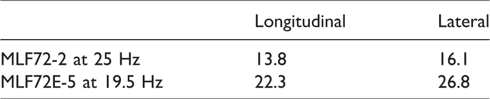
Robot damping coefficient K (mN.s/m) for two wings used in this project.
The damping forces associated with the wing motion constitute the dominant damping mechanism in the system and we will assume that all the damping forces can be reduced to a point force acting at the center of drag D and proportional to the linear velocity of the center of drag

The longitudinal (pitch) and lateral (roll) dynamics may be modeled in the same way; in the following, we limit the presentation to the pitch dynamics, using classical notations of aircraft dynamics. 17
Near hovering, the longitudinal dynamics is governed by Newton’s equation


(a) Pendulum experiment for the determination of the rotational damping constant Mq. (b) Magnitude of the damping coefficient
The equations may be written in state space, using the state vector 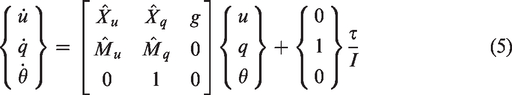
The characteristic equation reads

The pole pattern obtained with this fairly simple model is consistent with more elaborate models available in the literature.18–22
Passive stability with sails
Consider the system of Figure 5 where the flapping wing robot has been supplemented with two sails, a top sail of area S1 at z1 above the center of mass and a bottom sail of area S2 at z2 below the center of mass. Again, we assume that the drag forces acting on the sails can be reduced to point forces acting at the geometrical center of the sail, and proportional to the absolute linear velocity of the geometrical center:

Robot configuration with top and bottom sails (z1 and z2 are both positive; zd is positive if the center of drag D is above the center of mass C).
Drag force due to the axial velocity u

Pitch moment due to u

Drag force due to the rotational velocity q

Pitch moment due to the rotational velocity q

Notice that, once again, Mu = Xq. We will address shortly how the drag coefficients of the sails may be determined experimentally. Before this, let us consider the inertia properties of the system. The vertical equilibrium of the system implies that
Let m1 be the added mass of air associated with the top sail; the mass of air which can be regarded as the mass attached to the sail (e.g. see White
23
), and m2 the added mass of air of the bottom sail, that we assume lumped at the center of the sails, respectively at z1 above C and z2 below C. Newton’s equation describing the longitudinal dynamic equilibrium becomes


Added mass and damping of the sails
The sails appear in the foregoing equations through the viscous damping and the added mass (the mass of air which is moving with the sail), respectively
To evaluate the added mass and the damping coefficient, a vibration experiment was conducted in which the sail is attached to a cantilever beam (Figure 6); the beam is excited by a voice coil and the beam vibration is monitored with a laser vibrometer; the frequency response functions (FRFs) are recorded, first without sails and then with sails of various sizes. Additionally, a flapping wing mechanism is used to simulate the downward flow when studying the bottom sail. A finite element model of the system (cantilever beam + point mass and damper at the geometrical center of the sail) has been developed and the damping coefficient and the added mass of every sail are calculated by curve fitting on the FRFs (Figure 7). The good quality of the fit confirms the assumptions made.

Experimental setup for the determination of the added mass and damping of the sails. The sail is attached to the tip of a cantilever beam. A flapping wing mechanism (not used for the top sail) is mounted on a separate support to simulate the air flow acting on the bottom sail. d is the distance between the geometrical center of the sail and the wing root.

FRF of the system of Figure 6 for a top sail of various sizes (full line: experiment; dotted line: finite element model including an added point mass and damper at the geometric center of the sail).
The damping coefficient
Top sail damping coefficients and added mass of air.

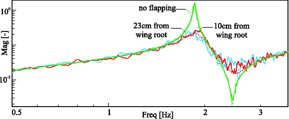
FRF of the system of Figure 6 for a bottom sail of 50 cm2 at various distances from the wing root (
Bottom sail of 50 cm2: damping coefficient and added mass of air as a function of the distance d between the geometrical center of the sail and the wing root, for wing MLF72-2 flapping at 21 Hz.

Flight experiments
Thirteen flight experiments have been conducted with the flapping wing robot equipped with top and bottom sails of various sizes (Figure 9); for every configuration, the position of the center of mass C was determined experimentally; the position of the center of drag D with respect to the center of mass is calculated by the formula

Flapping wing robot equipped with top and bottom sail stabilizers used in the flight experiments. The reflective markers used for motion tracking in the video room are also indicated.
Figure 10 and Table 4 describe the various configurations: mass, size of the sails,

Configurations used in the flight experiments. The weight of the robot equipped with sails in each configuration is shown below it.
Characteristics of the various flight configurations: mass, top and bottom sail area and position, added mass of air, position of the global center of drag

Stability derivatives of longitudinal (column 2–5) and lateral (column 6–9) dynamics for 13 flight tests with the configurations shown in Figure 10.

Eigenvalues of longitudinal (column 2 and 3) and lateral (column 4 and 5) dynamics versus the observations.

Figure 11 shows examples of pitch and roll signals recorded during flight tests. In order to capture the attitude, a room equipped with 8 OptiTrack Flex motion tracking cameras has been used. These cameras offer the resolution of 1280 px × 1024 px and the frequency of 120 frames per second (FPS). Five retroreflective markers were attached to the robot with a dissymmetric arrangement to avoid the loss of orientation and attitude from the tracking system. In analyzing Table 6, it is interesting to note that all the observed behaviors during the flights are in agreement with the predictions except for flight

Examples of pitch (left) and roll (right) signals recorded during flight tests in the video tracking room. From top to bottom: Stable flight (

Numerical predication of the real part
None of the flights with top sail only was stable.
All the twin sails flights with negative
All stable cases had a small positive value of
All predicted stable flights were observed stable with the exception of flight
The same conclusions apply to the lateral dynamics.
Conclusion
This paper has analyzed the dynamic stability of a flapping twin-wing robot near hovering; a very simple model (similar to those used in aircraft dynamics) decoupling pitch and roll has been used to show that the system is intrinsically unstable. The model has been used to study the passive stability enhancement with the addition of top and bottom sails. Experiments have been conducted to evaluate the parameters involved in the dynamical model; the experiments revealed that the damping coefficient of the bottom sail (located in the flow induced by the flapping wings) is significantly larger than that of the top sail and depends critically on the flapping frequency and the distance between the geometrical center of the sail and the wing root. Thirteen flight experiments have been conducted with sails of various sizes and the behavior of the robot was observed; 12 out of 13 flight experiments are in agreement with stability predictions of our simplified model. This led to trust the model and use it later for designing the controller, and achieving the actively stable flight. The study indicates that
Footnotes
Acknowledgements
The authors wish to thank the contribution of Ignacio Senet Capote, Mylène Dumon, Carlos Santos, and Georges Tod.
Declaration of conflicting interests
The author(s) declared no potential conflicts of interest with respect to the research, authorship, and/or publication of this article.
Funding
The author(s) received no financial support for the research, authorship, and/or publication of this article.