Abstract
This work investigates the design parameters and their consequences in the control of a helicopter rotor combined with a pair of fixed wings. This hybrid vehicle has a light and aerodynamically efficient rotor with a large range of pitch angles to enable both hover and forward flight. Because of the light stiff rotor and heavy wings, the hybrid vehicle exhibits couplings between the roll and pitch axes during hover flight. The rotor-wing interaction depends on a lot of parameters. In this article, we utilize a simplified theoretic model and simulations in order to gain insight in the effect of these parameters on the vehicle dynamics. Finally, a controller is designed that compensates undesired coupling between pitch and roll.
Introduction
Rotorcraft dynamics have been well studied for many years1–4 with work ranging from rotorcraft modeling in Johnson 5 and Cai et al., 6 rotorcraft simulation in Padfield, 7 over matching measurement data with models in Yamauchi et al., 8 to the blade optimization in function of vibrations in Peters et al. 9 The design of controllers for conventional helicopters is well understood as shown in Shim et al. 10 and Gavrilets. 11
For less conventional designs like hinge-less low inertia rotors or high inertia fuselages, the design choices and control problems are more complex. Ormiston 12 performed some studies into the fuselage-rotor interaction and fuselage ground interaction and has identified resonance problems.
On the scale of small unmanned helicopters, models were used in Caradonna and Tung 13 to identify which parameters affect the performance. Bernardini et al. 14 used a model to understand and reduce vibrations or noise. Recent work by Cai et al. 6 presents a comprehensive non-linear model of a miniature unmanned helicopter.
Heli-Wing hybrid
The helicopter with wings concept is a hybrid UAV and has been introduced by De Wagter et al. 15 While the central part is using a standard rotor head, due to the lower blade weights and huge fuselage inertia, the properties identified by previous literature do not describe the characteristics of an efficient helicopter with wings.
When designing a complex hybrid vehicle, it is crucial to gain deeper insight into the different parameters that affect control and performance. Therefore, the subject of this article is the identification of the design parameters and control properties of a conventional cyclic and collective pitch controlled light rotor on top of a fixed wing shaped heavy fuselage. Figure 1 shows the vehicle in semi transitioned attitude. A schematic drawing of the hover and forward flight states is shown in Figure 2. The rotor allows the vehicle to hover while the wings and rotor design enable efficient fast forward flight.
Novel hybrid Unmanned Air Vehicle featuring a cyclic controlled rotor with wing. Hover and forward flight.

The rotor blade design in the case of this vehicle is a compromise between efficient hover and efficient forward flight. This means the rotor is significantly different from rotors seen in conventional helicopters. It is relatively small, light, and stiff and it has a high lift coefficient. During forward flight, the rpm is reduced and pitch angle increased to generate propulsion efficiently. The large wings act as fuselage, and systems are distributed over the entire wing, giving it a large moment of inertia.
These properties significantly affect the way the conventional helicopter rotor behaves during hover. On the other hand, during forward flight, the propulsion gyroscopic effect is much larger than usual, which also has an influence on the vehicle’s dynamics.
In order to find an acceptable compromise between the dynamics in hover and forward flight, a mathematical model is created in the first section. In the next section, design parameters are varied. Following, the interaction between rotor and fuselage is investigated, and finally the model is used to gain insight in the flight test results of hovering flight.
Rotor model
To explore the design options and their consequences, a helicopter model is derived mathematically. Figure 3 illustrates a basic rotor model similar to Bramwell et al.
4
The flapping angle β is measured around the spring hinge K. The rotor radius is R and it is spinning with a rate ω. The inputs are deflections of the swash-plate around the body x axis δx and y axis δy. A positive input δx increases the pitch of the blade as it passes over the y axis.
Simplified rigid rotor model.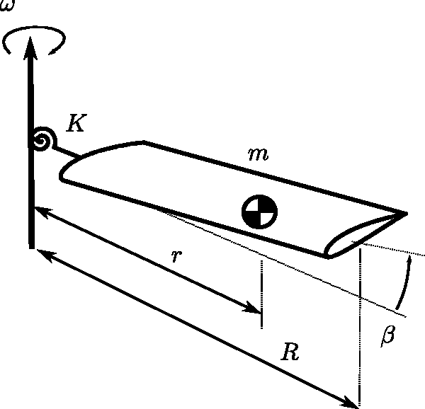
A blade element and its corresponding angles are illustrated in Figure 4. The model neglects the lagging angle of the rotor blade. The velocity Vx of the blade element then becomes ωr while the vertical speed of the blade element Vy is a function of the derivative of the flapping rate Angle of attack on a rotor section.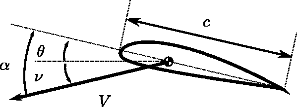

Since we are mainly interested in the lateral control properties, we will neglect collective pitch, meaning that there will be no induced velocity vi and the angle of attack of a blade element is


First the moments created by a blade element are integrated. The centrifugal force

Then the hinge spring moment
When linearizing equation (4), filling the lift force from equation (3), neglecting the very small contribution of gravity on the blade dynamics and integrating over a uniform rotor, the differential equation
4
for flapping around a fixed hinge is obtained:

Equation (5) relates the inertia of the rotor, the aerodynamic damping, and the centrifugal and spring forces to the excitation. The three main design parameters are shown to be the rotor rpm ω, the spring stiffness K, and the Lock Number γ, which relates the rotor lift properties to its mass properties.
In simulation, the rotor is defined as a finite number of sections and integral in equation (4) is replaced by a summation over all segments.
The excitation using feathering angle θ is periodic and a function of the control inputs δx and δy

Design variation
The derived model is analyzed in simulation. To gain insight into the design choices, several variables in the model that can be tuned in real life are varied over a range.
Hinged rotor
Figure 5 shows the results for a rotor with K = 0. Parameters for the model can be found in Tables 1 to 3. A deflection δy of 4° is applied. After a few rotations,
a
the rotor plane is tilted.
Blade dynamics based on cyclic deflection with zero spring stiffness K. Blade parameters. Fuselage parameters. Central rotor block spring mounts.


The deflection β has a phase lag of 90° with the perturbation θ as is expected in gyroscopes. ξ (see Figure 6) is equal to 90°. A positive cyclic deflection in pitch decreases the feathering angle θ whenever the rotor blade is at the right side of the vehicle with a ω clockwise spinning rotor, to yield a rotor-plane inclination backward.
Applied force 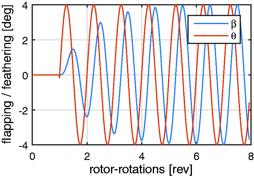
Stiff rotor
When the stiffness of the spring K is increased, the dynamics of the rotor are significantly affected. Not only is the deflection β reduced, but also the direction of maximal flapping—in other words the rotor plane rotation—is affected.
Figure 7 shows the results for a rotor system with a stiff spring (high K). In this case, the angle ξ, or in other words, the phase difference between θ and β, is reduced from 90° to below 30° for a spring K, which reduces the flapping angle β roughly by half.
Blade dynamics based on cyclic deflection with significant spring stiffness K.
Design parameters
The theoretic model gives great insights on how the real rotor head and rotor can be tuned or modified. Equation (5) shows that the dynamics of the rotor are affected by the rotor rotation rate ω, Lock Number γ, and spring stiffness with respect to rotor inertia K/I.
Practically, however, for a given amount of lift and given size, the rotation rate is quite determined and the Lock Number γ can only be altered easily by changing the rotor weight. The rotor weight will mainly influence the speed of the response. The spring stiffness K can be changed easily and affects the dynamics of the rotor significantly.
Rotor head and fuselage
Rotor head model
Since the previous sections have shown the importance of the hinge spring, the model of the actual rotor is investigated further. Figure 8 shows a cross section of the helicopter rotor head used in the platform from Figure 1. It consists of an aluminum head block on a main rotor shaft. The shaft holding both blades is only connected to the hub via rubber o-rings. A close up can be seen in Figure 9.
Actual rotor hub simplified schematics. Close up of the rotor head of the hybrid winged helicopter vehicle. The swash-plate has 3 servos at 120° from each other. Collective pitch has much greater reach than conventional helicopters and the blades have more twist to allow efficient forward flight.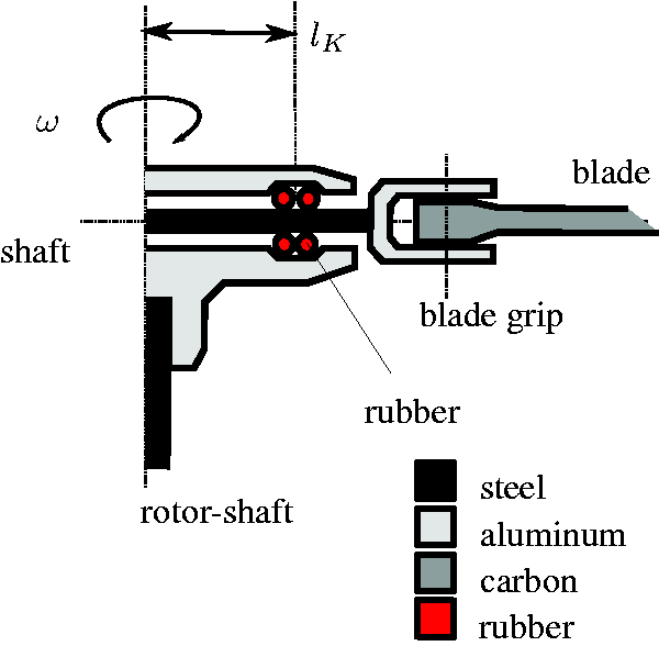

Modeling the bending of all parts of the rotor is complex. The exact bending of the feathering shaft, the blade grips, and the blade itself contain a large number of parameters. Modeling how the force is transferred from the rotor system to the main rotor shaft is simplified by modeling only the rubber o-rings with linear stiffness Simplified rotor hub.

Equation (5) is using a torsional spring constant K. The relation between the linear spring constant 
Constrained rotor-shaft motion
When the rotor shaft is rotated in pitch or roll to simulate a fuselage change in attitude, the rotor plane is following the fuselage motion. Figure 11 depicts the simulation results of a 10° pitch up of the fuselage and main rotor shaft in the case of a pure hinged rotor with K = 0 and in the case of a bending rotor with K non-zero.
Rotor dynamics in function of fuselage imposed motion. Left K = 0, right 
In the case of a fully hinged rotor, the rotor disc still tracks the motion of the rotor-shaft, as the feathering angle of the blade remains parallel to the rotor shaft through the swash-plate dynamics. When neglecting the blade grip push-rods and swash-plate forces, the moment from rotor to rotor shaft is zero.
On the other hand, whenever a moment can be transferred from the rotor to the rotor-shaft, it can be seen that the relative blade flapping angle βshaft creates moments Mx and My with a frequency of
It is interesting to note that a pure imposed pitch motion will generate moments in both Mx and My directions. The fuselage applies a moment to the rotor to make it pitch up, but the gyroscopic reaction of the rotor on that pitching motion is a rolling motion. This yields a roll moment from the rotor on the fuselage in return.
This is of particular importance in the case of a partially constrained fuselage. For instance, upon landing of the vehicle from Figure 1 with a roll angle, one tip will touch the ground first, yielding a constrained roll rate imposed on the rotor. As shown in Figure 11, this results in significant pitch moments imposed back from the rotor on the fuselage. This can lead to undesired pitch motions caused by imposed roll motions.
Similarly, in forward flight, a pitching moment from the fixed wing and its elevons will cause an undesired yawing moment from the rotor back on the fuselage.
Free fuselage dynamics
To simulate the free fuselage dynamics, the fuselage is modeled as four point loads of a quarter of the total mass, as depicted in Figure 12. The fuselage is symmetric around the x and y axes, but the dimensions are not equal.
Body model.
The distance from the vehicle center of gravity to each modeled point load mwing in the x direction is lx and in the y direction is ly.


Assuming no aerodynamic forces on the wing during hover, no yaw rate, and small angles, the fuselage rates are obtained through integration of the rotor shaft moments.


Using this simple vehicle model, the interaction between the rotor and the fuselage can be simulated. In Figure 13, three of these simulations are shown, for different values of lx and ly. For all three simulations, the same inputs are applied, shown in the top left figure. Clearly, the distribution of fuselage inertia over the X and Y axes has a big influence on the way the vehicle reacts to inputs.
The influence of fuselage inertia on a free body. Three simulations of an identical rotor with identical non-zero stiffness and different inertia distribution of the fuselage.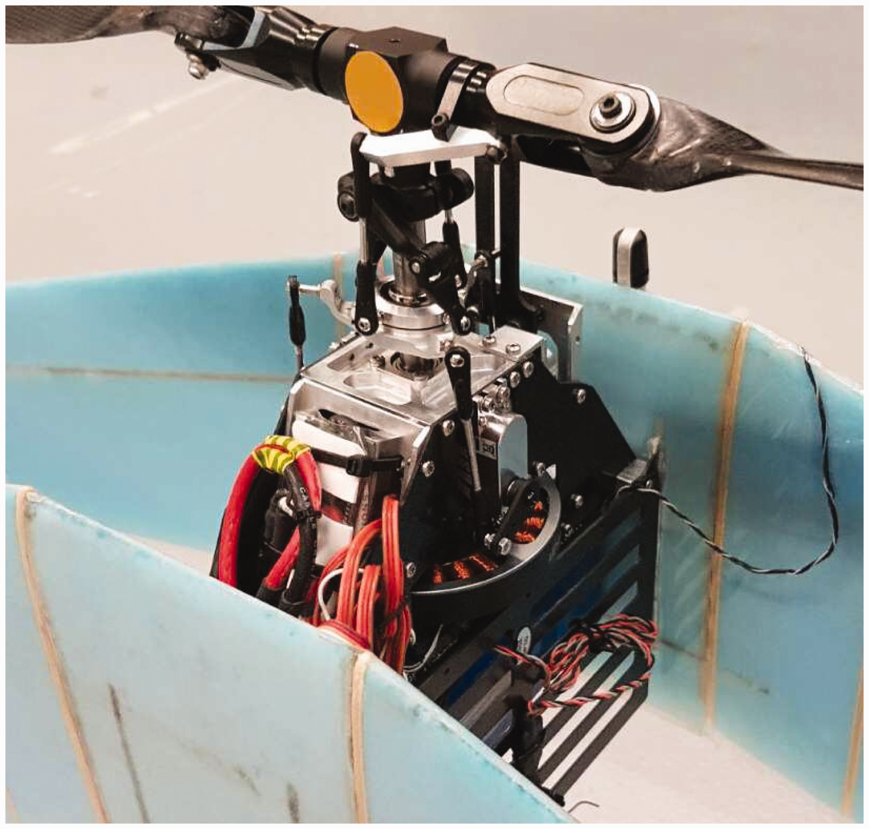
Control considerations
The insights from the derived models were applied to the control of the hybrid rotor-wing vehicle depicted in Figure 1. It has very light, stiff, and relatively small carbon-fiber rotor blades, mounted on a stiff conventional Logo-480 rotor head with modified blade grips and doubled pitch range. The rotor blade airfoils are highly cambered to obtain high lift coefficients. Parameters of the vehicle are given in Tables 1 to 3 and in De Wagter et al. 15 The wing-shaped fuselage is very wide and heavy. This combination is not behaving like a conventional helicopter anymore.
To obtain real flight tests data, the vehicle was equipped with an autopilot with a simple low gain rate controller. A governor was also programmed to yield a constant rpm and hereby remove extra variables from the problem. Figure 14 shows the rpm is kept constant as soon as the vehicle takes off. The flight controller used is the paparazzi autopilot project as described in literature.16–18
Test flight RPM.
In steady conditions, the vehicle can just be kept airborne with a simple low gain proportional controller that controls the vehicle’s angular rates. The output of this controller is cyclic commands, which are mapped to the three servos that control the swash-plate. The feedback was initially done with a 90° offset (see Figure 6), such that roll feedback was applied to δx and pitch feedback to δy. δx produces a moment in the pitch axis and δy produces a moment in the roll axis. Due to gyroscopic precession, this then produces an angular rate in the desired axis. This method of control is very common for helicopters. 4
For the vehicle in question, this controller did not provide control without couplings. Inputs of the pilot resulted in rates in a different axis than intended and on top of that a transient “wobble,” where the vehicle oscillates in both pitch and roll with a 90° phase difference. Using onboard logging on an SD card, all turn rates and control deflections were logged.
These data were used to model the angular acceleration in pitch and roll in function of the inputs δx and δy, the rates in roll and pitch and an offset O = 1. The model is shown in equations (13) and (14), where fp and fq are linear functions of the parameters.


From the first data-set, it was discovered that the control mapping was incorrect, as δx and δy both caused a roll as well as a pitch rate acceleration. This was expected to cause some of the problems, which is why a second test flight was conducted using the corrected control mapping.
Figure 15 shows the angular acceleration in roll and pitch along with the best fit of Fitting control inputs and body rates to body accelerations. In blue, the filtered angular acceleration and in red the best model fit. Flight with Kc = 0. Identified parameters.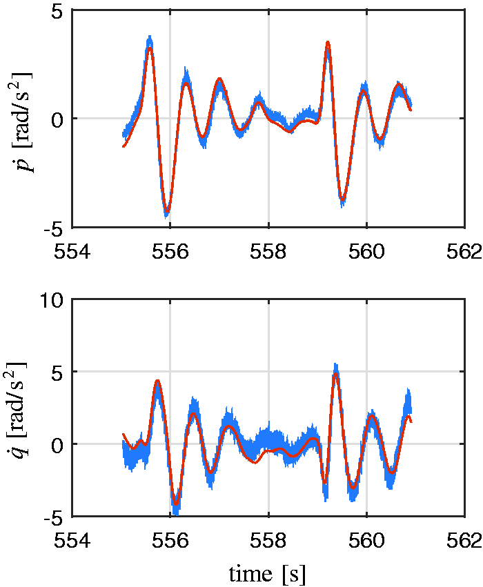

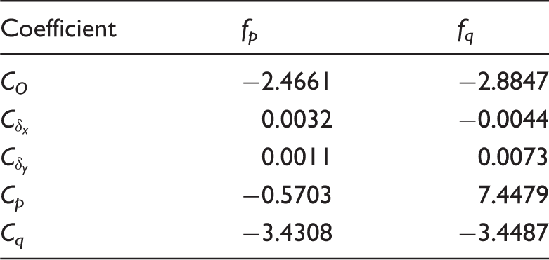
Note the coefficients for Cp and Cq. They state that a roll rate causes a pitch acceleration and vice verse. This might well explain the observed wobble. Therefore, in order to remove the wobble, the angular acceleration due to the rates needs to be canceled by a control input. The linear controller is revised to:


And Kc is a value between 0 and 1. Kc was introduced in order to gradually enable the compensation of angular acceleration due to rates. Test flights showed that a value of 0.5 gives better results than a value of 1. This may be caused by actuator dynamics, as a control moment can not be instantly generated when a rate is measured. More research is necessary to better explain why Kc = 1 still gives a wobble.
Figure 17 shows the measured angular rates of the vehicle during some pitch maneuvers in the first part of the flight (t < 598 s) and some roll maneuvers in the second part of the flight. The rates were filtered with a second-order filter with a cutoff frequency of 25 rad/s. From this figure, it can be seen that no wobble is present, and the motion in roll and pitch is uncoupled. Compare this to Figure 16, where Kc = 0 results in clear coupling between roll and pitch.
Flight with 
Conclusion
When designing hybrids between conventional cyclic controlled helicopters and fixed wings, it is crucial to understand the interactions between rotor and wing in order to optimize the design. Although a simulation model can not provide direct control parameters, it can help understand the variables affecting performance and control.
Lock Number was shown to influence the response speed of the rotor while rotor hinge spring stiffness was shown to influence the amplitude of the rotor rotation and even direction of the control effectiveness. Compensation for actual control effectiveness was needed in the controller to obtain correct steering and feedback.
Non-homogeneous inertia of the fuselage and fuselage-rotor interactions add non-symmetrical coupling between the pitch and roll axes. Compensation for gyroscopic effects was needed in the controller to remove this coupling.
In future research, we want to identify more of the parameters discussed in the theory section of the article, in order to better predict the response of the vehicle to inputs. This information is vital in improving the performance of the current controller. Also, we want to investigate how the helicopter dynamics influence the dynamics in forward flight.
Footnotes
Acknowledgements
Declaration of conflicting interests
The author(s) declared no potential conflicts of interest with respect to the research, authorship, and/or publication of this article.
Funding
The author(s) received no financial support for the research, authorship, and/or publication of this article.
Supplemental material
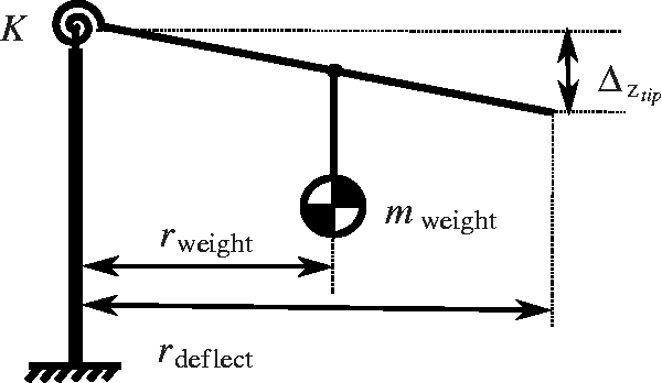
Parameters of the model are supplied below: To assess the stiffness of the central rotor block rubbers, a setup was created using a dummy weight to measure the increase in deflection as shown in Figure 18 with parameters from To measure the stiffness of the hinge springs and blade of the real aircraft, a measurement setup was created. A constant weight was added to the blade at a given distance and the resulting deflection was measured.![]() .
.