
Abstract
Recently, flapping wing micro air vehicles have received great attention with the drive to make smaller and smaller devices. This paper describes a theoretical investigation and subsequent practical implementation of a specific type of flight motor structure for this type of micro air vehicle that uses a “click” mechanism to improve mechanical efficiency. Diptera, which may use the mechanism, are the inspiration for this work. It builds on previous research into the “click” mechanism, which has been studied both from the biological and engineering points of view. It is difficult to capture the important fine details using a simple analytical model; hence, a multi-body dynamic software is used to model the device and to aid the design of a large-scale prototype. Force–deflection curves of the structure and the displacement response are obtained numerically and experimentally. The experimental and numerical results compare reasonably well, enabling the model to be used for further development and potential miniaturization of the flight motor structure. In a practical device, asymmetry occurs in the up- and down-stroke. The effects of this asymmetry are compared with previous results from analytical models. It is found that asymmetry offers a marginal improvement.
Introduction
Research into micro air vehicles (MAVs) has received great attention recently, because of the drive to make smaller and smaller devices. It has been an important area in biomimetic research for about two decades.1–3 Recently, some MAVs have been reduced to the scale of a fly. 4 By comparing two different flight motor mechanisms, such as the flapping wing or the rotary wing, it has been found that the rotary wing has a higher power density (power to weight ratio). 5 However, for a very small scale MAV with high maneuverability, the flapping wing system may still be attractive.5,6 A high degree of understanding of both aerodynamic theory and the dynamics of the flight motor mechanism are necessary to improve the performance of flapping wing MAV.
In the search for a suitable flight motor for a flapping wing MAV, some researchers have turned to nature for inspiration. Many models for the flight mechanism of diptera have been proposed, one of which is the “click” mechanism, an overview of which is given in Overview of a simple model of the “click” mechanism section. The “click” mechanism was first proposed in Boettiger and Furshpan, 7 Pringle 8 and Thomson and Thompson 9 derived a mathematical model for the “click” mechanism. It is called “click” mechanism because when the excitation force on the wing structure of diptera reaches a critical value, the wings suddenly “click” from an up to a down position at a high velocity. This interesting phenomenon is due to the bistable characteristic of the structure, and in engineering parlance is often called a “snap-through”. Alexander and Bennet-Clark 10 analyzed the benefit of the “click” mechanism in the storage of elastic strain energy. Miyan and Ewing11,12 expressed doubt about the existence of the “click” mechanism using morphological analysis. However, a revised model by Miyan and Ewing 13 shows a weak version of “click” mechanism in an inherently asymmetric structure. The new model attracted the interest of researchers and was reported by Bennet-Clark 14 and Gronenberg. 15 Ennos analyzed the distortion of the whole thorax and gave a novel linear model. 16 The new model given in Miyan and Ewing11,12 was also criticized by Pfu who modified the “click” mechanism with a gear change structure. 17 Recently, Pfu built a mechanical model with both “click” and gear mechanisms to test the plausibility of the gear change mechanism. 18 The gear mechanism18,19 was put together with a clutch mechanism recently by Deora et al. 20
Based on the flight mechanism described in Thomson and Thompson, 9 Brennan et al. 21 and Tang and Brennan 22 analyzed a simple mechanical model of the “click” mechanism with both linear and quadratic damping, to determine if it gives any mechanical advantage. Motivated by this work, Chin and Lau23,24 and Lau et al. 25 built a flapping-wing MAV, incorporating such a mechanism, and recently, Harne and Wang 26 used a compressed beam mechanism in a “click” mechanism for an MAV. Kok et al. 27 used a quasi-steady blade-element method to analyze the asymmetrical flapping on the aerodynamic efficiency of half-span wing of the MAV with “click” mechanism which was built by Chin and Lau,23,24 observing greater lift generation when the wing was excited below the natural frequency of the system.
The aim of this paper is to build on previous theoretical work, investigating the practical implementation of “click” mechanism, and to determine whether it offers any significant improvement in the mechanical efficiency in a practical device. A large-scale device is studied (because of resource limitations), but the practical device and the accompanying numerical model can be used in further studies of smaller scale devices. A practical issue that has not been addressed hitherto, and is of particular interest in this paper, is that a flight motor structure with a “click” mechanism may have unavoidable geometrical asymmetry between the up- and down-stroke. One element of this research that sets it apart from previous work is that the flight motor structure is studied both theoretically and experimentally, resulting in a validated model that can be used for further development work and research.
Overview of a simple model of the “click” mechanism
The flight motor described in Thomson and Thompson
9
and the related simplified mechanical model described in Brennan et al.
21
and Tang and Brennan
22
are shown in Figure 1. Figure 1(a) to (c) shows the three successive positions of the wing articulation during the course of a beat. Figure 1(d) to (f) shows the corresponding positions of the simplified model, in which the mass m at point C is the equivalent mass of the moving part of the whole mechanism given in Figure 1(a) to (c); BE and DF are the mass-less flexible links which represent the pleural apophysis (pa) and notum (n), respectively; BAC and CD are the mass-less rigid links which represent axillary sclerite 2 (ax2) and parascutum (p) respectively, and WA is the simple mass-less model of the wing. The harmonic excitation force is f(t) = Fcosωt, where F is the amplitude and ω is the angular frequency. It is applied at point C, while the input for the insect model is applied to the scuteller lever (sl).
Diagram showing the flight motor (a–c) and physical model (d–f) of an insect and three successive positions of the wing articulation during the course of a beat, from the down position (a or d) to the up position (c or f). In (a–c), ax1, ax2 – axillary sclerites 1 and 2; n – notum; p – parascutum; pm – pleurosternal muscle; pn – anterior notal process; pw – wing process; rv – base of radial vein; sl – section through scutellar lever ((a–c) After Thomson and Thompson
9
). pa- pleural apophysis (not shown in (Pringle
8
)). In (d–f), m: equivalent mass; BE, DF: mass-less flexible link; ABC, CD: mass-less rigid link; WA: wing.
The displacement of the mass from the position in which BCD is horizontal is given by y, and the lateral displacement of the cantilevers BE and DF is denoted by x. The simplified mechanism is assumed to be symmetric as shown by Brennan et al.
21
and Tang and Brennan,
22
which means that BC = CD = l and the distance between vertical undeformed link BE and point C (DF and C) is b. The equation of motion for the simplified model is then given by

Recent research on a flapping flight mechanism that utilizes the “click” mechanism has shown that, in certain circumstances, it has some advantages compared to that which uses a linear mechanism.21–27 This is primarily for small devices where the natural frequency of the system is too high for resonance to be utilized as the wing flapping frequency. In such a case, it is necessary to flap the wings at a frequency well below the natural frequency, and in this case, the “click” mechanism has advantages. This was demonstrated in Brennan et al.
21
and Tang and Brennan
22
by showing that, for a highly damped system, the peak kinetic energy of the wing root normalized by power input to the mechanism is larger than that of the linear system, as shown in Figure 2(a)21,22 for a system in which the excitation frequency is 1/10 of the natural frequency (the definition of the ratio of peak kinetic energy to work input is given in Appendix 2). This is because the peak velocity of the wings is increased by the “click” mechanism compared to the linear system for a given input frequency, providing a larger lift force. To illustrate the way in which the “click” mechanism changes the velocity of the wings, the normalized velocity is plotted in Figure 2(b) as a function of non-dimensional time for Comparison between the linear system (dashed line) and the system with the “click” mechanism (solid line). (a) Ratio of peak kinetic energy to work input as a function of excitation force amplitude, (b) non-dimensional velocity when 
Model of the flight motor structure with a “click” mechanism
An example of a flight motor structure with a “click” mechanism is depicted in Figure 3; a photograph is shown in Figure 3(a) and a schematic in Figure 3(b). It should be noted that this system was not intended to fly. It was a first attempt to study the practicalities of designing and testing a structure, which incorporates the “click” mechanism, and therefore it is much larger than a practical flapping wing MAV would be. The frame of the flight motor structure (pleural apophysis) is made from 0.5 mm thick carbon fiber-reinforced polymer (CFRP). The hinge for the flight motor wing, marked hinge I, consists of two 55 µm thick layers of polyimide film tape, which are bonded together, and hinge II consists of a single layer. The wings are made from polyethylene terephthalate polyester (PET) film and are 12.5 µm thick. The two pieces of CFRP, which are used for the tergum, are connected by one layer of polyimide film tape. A polyimide cylinder, which acts as the tergum hinge, is fixed on the top of the film. The driving mechanism is a DC motor, which can develop a maximum torque of 0.92 mNm, and connects to the tergum hinge through a crank and connecting rod mechanism. The dimensions and the masses of the flight motor structure are given in Figure 3(c) and Table 1, respectively, and the approximated simple mechanical model is given in Figure 3(d).
Flight motor structure with click mechanism (a) photograph with 50 Chinese cents, (b) multi-body dynamic model, (c) dimensions of the structure (units in mm), (d) simple lumped parameter model (dashed line, unstable equilibrium position), and f (y) is the nonlinear restoring force given by the two vertical uniform cantilever beams. Masses of the structure (see Figure 3).

Although it is possible to derive a detailed analytical model of the flight motor structure, it would be highly complicated. A more appropriate approach is to develop a multi-body dynamic model using commercial software to predict and study the behavior of the system, and here ADAMS (MSC Software Corp, USA) is used. The pleural apophysis, pleura process, tergum, tergum hinge, and wing frames are modelled as rigid bodies with a density of 1758 kg/m3. The wing film is also modelled as a rigid body with a density of 1400 kg/m3.
The two pairs of wing hinges are modelled as flexible elements with a Young’s modulus of 2.5 GPa and a density of 1400 kg/m3. Wing hinge I, which consists of two bonded layers of polyimide film tape, is modelled as two parallel polyimide films, each 55 µm thick. Wing hinge II, which behaves as a rigid revolute joint, is modelled by setting the Young’s modulus of the material to be one eighth of the actual Young’s modulus. To simulate the elastic characteristics of the flexible joints, the wing hinge elements are analyzed using ANSYS (ANSYS, Inc., USA). The first two natural frequencies and mode shapes of the wing hinge elements are saved in an MNF file and imported into ADAMS. To simulate the aerodynamic force, a damping element is created in ADAMS and located vertically between the tergum hinge and the pleural apophysis. Using the multi-body model, the restoring force, the dynamic response, and the energy consumption can be determined. The natural frequency of the whole model, estimated using ADAMS, was found to be about 12.5 Hz. This is the primary frequency of the whole structure when the moving parts of the structure oscillate around one of the stable equilibrium points as shown in Figure 1(d) or (f).
Force–deflection characteristic
The force–deflection characteristic of the flight motor structure depicted in Figure 3(a), as seen by the electric motor, was measured using an Instron Micro Tester 5848 (Instron, Norwood, MA, USA) with a 5 N load cell and 20 Hz sample rate. The test-rig is shown in Figure 4. As shown in the inset, the pleural apophysis was fixed, and the tergum hinge was connected by a metal rod to the moving part of the Instron Micro Tester, which was excited at a rate of 18 mm/min. During the test, the motor was replaced by a solid plastic block to maintain the operational shape of the flight motor structure frame. The wings were also removed. As well as measuring the force applied to the tergum and the resulting displacement, a video of the structural deformation was taken using an IXUS 210 Canon camera as shown in Figure 4. Because the test process was quasi-static, the camera was easily synchronized with the load step of the Instron Micro Tester, and the deformation of structure, force load and displacement of the structure could be captured at the same time.
Measurement of the force–deflection characteristic of the structure.
The measured applied force on the tergum and the displacement of the tergum are plotted together to give the force–deflection curve shown in Figure 5 as a solid blue line. Also shown in this figure are some pictures (video-stills) of the flight motor structure, at positions labelled (A) to (G). Superimposed on the measured force–deflection curve is the predicted force–deflection characteristic of the model of the structure shown in Figure 3(b), and the corresponding deformation of the structure, both calculated using the multi-body dynamic model. To obtain these quantities, the tergum hinge joint of the model was excited with quasi-static displacement excitation.
Measured and calculated restoring force. Circle  , multi-body model; solid line
  , experimental results. (a) and (g), tergum down and up points; (b) and (f), stable equilibrium points; (c) and (e), local maximum force points; (d), unstable equilibrium point.
As shown in Figure 5, it can be seen that the force–deflection characteristic obtained experimentally and that obtained from the multi-body model, agree reasonably well. The main difference between the two is the hysteretic behavior that is clearly evident in the experimental structure due to the structural damping in the hinges, which is not seen in the simulations, as this was not incorporated in the multi-body model. The asymmetric behavior of the flight motor structure is also clearly evident, with the structure being much stiffer on the up-stroke compared with the down-stroke.
Displacement response
The setup for dynamic displacement measurement is shown in Figure 3(a). The flight motor structure was driven by the electric motor with a rotation speed of 162 r/min (2.7 Hz). As in the previous experiment, the camera was used to capture the deformation of flight motor structure. To extract the displacement response of the tergum from the measured images, the computer program Tracker was used.
28
The displacement is shown in Figure 6 together with the response from the multi-body dynamic model. In the model, the damping coefficient was set to 1.5 Ns/m and the excitation force amplitude to 0.2 N, which are used to simulate the damping effect and the excitation load on the moving parts of the prototype structure respectively. It can be seen that the numerical results and the measured response compare reasonably well. This means that the model can be used to investigate some of the features of the MAV structure with “click” mechanism, and this is done in the following sections.
Experimental and simulated displacement response of the tergum. Simulations from the multi-body model (solid line) and experimental results using Tracker (dashed-dotted line with thick dot).
Effects of asymmetry
To investigate the effects of the asymmetry of the device, the velocity of the tergum was first calculated using the multi-body dynamic model and is shown in Figure 7(a). Further analysis is possible by developing a single-degree-of-freedom (SDOF) approximate model of the system, which is given by
Time history response for velocity of (a) the tergum of multi-body model, (b) simple model given in equation (2), and (c) simple symmetric lumped model.


The velocity response of the simplified SDOF model is shown in Figure 7(b). By comparing Figure 7(a) and (b), it can be seen that the simplified SDOF model captures the general behavior of the multi-body model. Note, however, that the multi-body model was necessary to capture the fine details of the system, from which the lumped mass and stiffness characteristics were determined. By retaining only the odd order terms in the approximate expression for the restoring force, a symmetric system can be obtained. The velocity of this system is shown in Figure 7(c). By comparing Figure 7(b) and (c), it can be seen that the asymmetry has the effect of inducing a larger peak velocity during the down-stroke. This may be considered advantageous as it may generate a larger lift force.
Energy considerations
As the simulations and the experimental results for both the stiffness characteristics and the dynamic response of the flight motor structure compare reasonably well, the multi-body dynamic model and simplified lumped parameter model can be used to further investigate some additional characteristics of the flight motor structure. Of particular interest is the ratio the energy ratio of peak kinetic energy of the wings and the work input per cycle which is given by
30
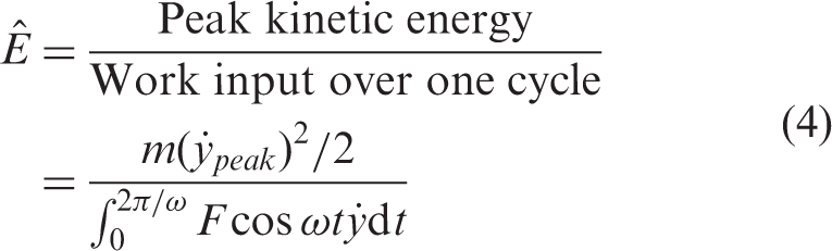
This can be used as a metric to characterize the efficacy of the structure. For the simplified lumped parameter model shown in Figure 1(d), the peak kinetic energy Energy ratio comparison at ω = 1.25 Hz. Circle  , multi-body model; solid line
  , simple model given in equation (2); dotted line
  , simple symmetric lumped model; dashed-dotted line
  , linear system.
It can be seen that all the systems which have a “click” mechanism perform better than the linear system. It can also be seen that the symmetric system and the asymmetric system behave in a qualitatively similar way, but the asymmetry, which is hard to avoid in a practical flight motor design and observed in the wing motion of insects, offers a marginal improvement.
Conclusions
A bio-inspired flight motor structure with a “click” mechanism, which was realized using polyimide film and CFRP, has been investigated numerically and experimentally in this paper. Asymmetry, which occurs in the up- and down-stroke in the practical flight motor structure studied, has also been considered. The numerical analysis was carried out using both a multi-body dynamic model and a simple lumped parameter model. The experimental and numerical results for the restoring force and displacement response compared well, meaning that the multi-body dynamic and lump parameter models can capture the dynamic characteristics of the asymmetric flight motor structure reasonably well. The energy ratio of the kinetic energy to work input over one period of excitation was subsequently obtained from the numerical models. It was found that the symmetric and asymmetric structures have a similar performance when the energy ratio of the kinetic energy to work input over one period of excitation is chosen as the criterion, with the asymmetric structure being marginally better. Although a large-scale device has been studied in this paper (because of resource limitations), the advantages of the “click” mechanism have been demonstrated practically and the numerical model developed can be used in further studies of smaller scale devices.
Footnotes
Acknowledgements
The authors thank Dr. Yao-Wei Chin, Dr. Rong Yang and Dr. Yihui Feng who helped during the experiments.
Declaration of conflicting interests
The author(s) declared no potential conflicts of interest with respect to the research, authorship, and/or publication of this article.
Funding
The author(s) disclosed receipt of the following financial support for the research, authorship, and/or publication of this article: The first author wishes to acknowledge the financial support from the National Natural Science Foundation of China (Grant Nos. 11202048 and 11672058), the Fundamental Research Funds for the Central Universities of China (Grant No. DUT15QY30).