
Abstract
This paper discusses the design, hardware and software methodology, and testing of an ultralight inertial navigation system (Embedded Lightweight Kinematic Autopilot-Revised (ELKA-R)) that can be used as a controller in a wide range of micro air vehicle systems. ELKA-R was designed using the 32-bit low-power ARM Cortex-M4 microprocessor as the microcontroller unit. The microcontroller unit interfaced with state of the art 9 degrees-of-freedom inertial measurement unit using inter-integrated circuit communication (I2C) protocol. A wireless transceiver was also incorporated with serial peripheral interface to wirelessly coordinate pilot inputs and sensor information with a remote basestation. Multiple timer protocols were configured to generate individual driver signals to a wide variety of motor and actuator configurations. The printed circuit board was designed as a four layer layout. ELKA-R weighed 1.7 g with a board area of 4.82 cm2, thus making it one of the smallest and lightest kinematic autopilots in open literature that can be applied to any generic micro air vehicle system. ELKA-R was tested on a variety of micro air vehicle flight demonstrators. Hover stabilization rates of 1000 Hz were achieved which were comparable to the autopilots on larger quad rotor systems such as DJI Phantom and AR-Drone. Oscillations in attitude were reduced by up to 50%–70% when compared with a previous generation lightweight autopilot.
Introduction
Unmanned air vehicles are controlled by embedded circuits through a remote operation by a ground operator. This represents one of the key elements that ensures vehicle functionality. With the rapid progress in micromechanics, microprocessing, and microelectronics, there is a demand for smaller and lighter autopilot development that can enable operation of increasingly unstable air vehicles with faster dynamics.1,2
To control and stabilize small micro air vehicles (MAVs), there is a significant need to reduce the weight fraction of the autopilot and avionics units so as to maximize the payload capability and endurance of these vehicles. Although multi-functional and capable, most of the existing autopilots in open literature weigh more than 5 g. 3 Therefore, for a 20 -g vehicle, it accounts for at least 25% of the gross weight, which is not desirable. Additionally, the choice of autopilot circuitry that weighs less than 1.5 g and with a low power consumption is not available in open literature. An existing candidate autopilot (GINA Mote), developed at University of Berkeley, 4 includes an onboard inertial sensing unit and a wireless transceiver. While this board is relatively small, 25 mm × 25 mm, and lightweight (1.6 g), it has been more than three years since new modifications. Thus, many components and features such as sensor and microcontroller capabilities are outdated. Additionally, the 16-bit microcontroller may be a limitation for some advanced computations. For example, it supports an attitude stabilization rate of only 333 Hz which may be insufficient to stabilize unstable MAVs or in the presence of external disturbances.
Therefore, the aim of the present work was to develop an improved lightweight autopilot with a faster core and better sensors. In achieving this, the authors initially designed an Embedded Lightweight Kinematic Autopilot (ELKA
5
). The present work extends on this development by integrating a real-time operating system (RTOS) to handle various microcontroller tasks, as well as a complete design of a refined autopilot system (ELKA-R) that is controlled by an ARM Cortex-M4 microprocessor. Thus, with the new design, it was possible to achieve stabilization rates as high as 1000 Hz. In order to comply with low power and low weight specifications, the system was designed as simple as possible while allowing the possibility of accessing various peripherals through external connectors. Furthermore, flexibility and hardware independency was desired in order to use this board not only on a specific class of vehicles, but one that can be easily adapted from ground vehicles to aerial vehicles. Both ELKA and ELKA-R were comparable to the size and weight of GINA mote as shown in Figure 1 and salient features are compared in Table 1.
Comparison of ELKA-R with previous generation inertial navigation system, ELKA and GINA Mote. All of them weigh under 1.7 g and have an area less than 6.5 cm2. ELKA-R offers higher inertial stabilization rates (1000 Hz) when compared with ELKA (500 Hz) and GINA Mote (333 Hz). Comparison between GINA Mote, ELKA, and ELKA-R. ELKA-R: Embedded Lightweight Kinematic Autopilot-Revised

The paper initially discusses the hardware on ELKA-R and some of the considerations used in the various component choices. The communication layers between the microcontroller and the other peripherals are detailed. The firmware and attitude estimation techniques that are needed for operation of ELKA-R are described. Finally, results from implementation of ELKA-R in candidate MAV platforms are shown.
Hardware
The block diagram of the main components of ELKA-R is shown in Figure 2. It consists of (1) microcontroller unit (MCU), (2) inertial measurement unit (IMU), and (3) wireless transceiver. Additional features are provided as breakout pins to drive actuators, read analog signals, and universal asynchronous receiver/transmitter communication (such as from external GPS units, satellite receivers, and image-based sensors). This section gives an overview of the various components of the board.
Overview of components in ELKA-R.
Inertial measurement unit
Specifications for MPU-9150 IMU.

The gyros measure angular rates up to ±
A histogram of the noise levels of gyro taken from a sample of 4000 measurements when the IMU was in rest condition is shown in Figure 3. It can be seen that due to temperature compensation, there is minimal drift in gyro mean. Also, the raw values can mostly be approximated as a zero-mean additive white gaussian noise in addition to mean angular rates. Similar observations were made with the accelerometer measurements as well, with a total RMS noise within 0.005 g.
Distribution of noise in gyro measurements from 4000 samples in rest condition.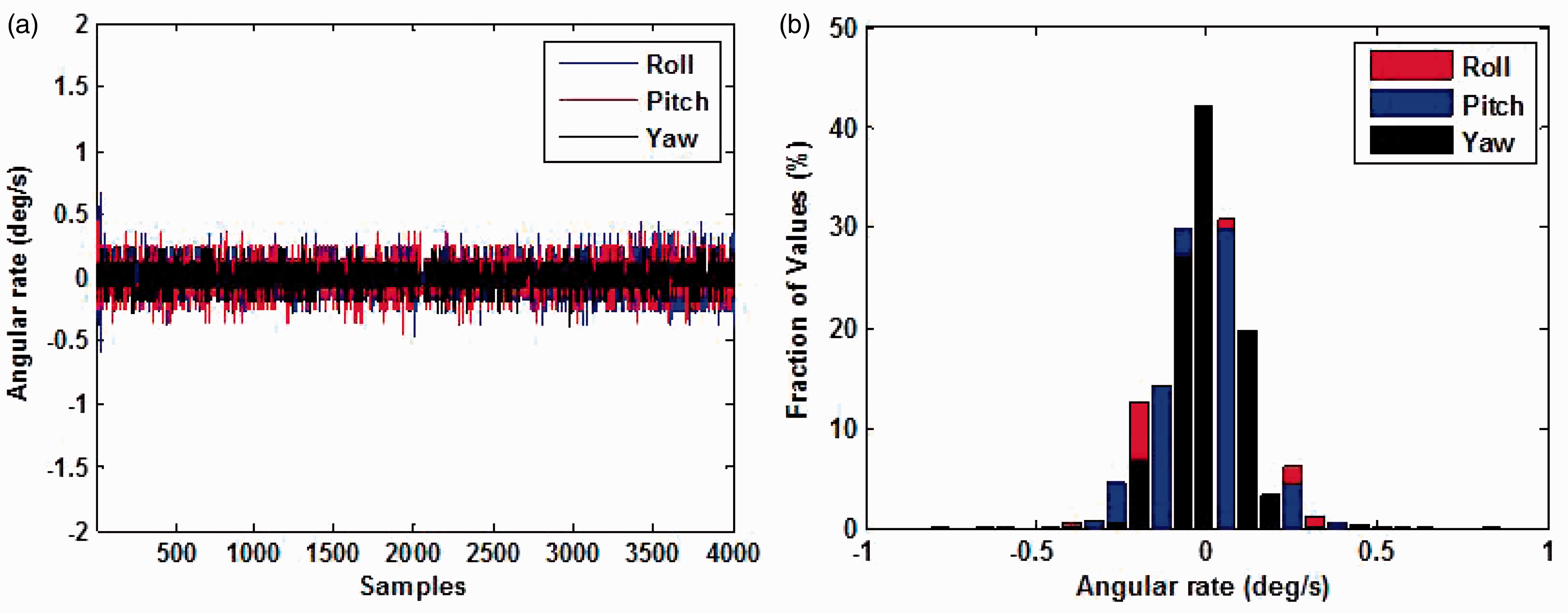
Wireless transceiver
One of the key capabilities of the board is to accept wireless inputs from a remote basestation as well as transfer sensor information for data logging. Communication to the board is handled by a wireless transceiver module (nRF24L01 8 ). It is designed for operation in the industrial, scientific, and medical frequency band at 2.4 GHz. It is configured and operated through a Serial Peripheral Interface (SPI) through which various configuration registers are accessible. This chip features an Enhanced Shockburst packet communication, which enables stable bi-directional half-duplex communication. The air data rate supported by the transceiver is configurable to 2 Mbps. This high air data rate when combined with onboard power saving modes makes it very suitable for ultra low power designs. It has an input power supply range between 1.9 and 3.6 V and consumes about 20 mA under bi-directional communication at 250 Kbps. The 20 pin package has an area of only 16 mm2. Three separate 32 Byte TX and RX FIFO registers are available to transfer and receive data packets between ELKA-R and a remote basestation. Instead of a monopole wire antenna, a surface mount chip antenna with a gain of −0.5 dBi is included to conserve space on the board and to minimize losses. Generally reliable communication up to about 50 ft in an uncluttered line-of-sight environment was achieved. Care may need to be taken to mitigate interference and multipath effects. To further enhance range, an antenna with a gain of +8dBi or higher may have to be integrated with the board. However, the drawback is a significant increase in size and weight of the board.
Processor
Comparison between candidate 16-bit TI and 32-bit ARM Cortex M3 and M4 MCUs.

SPI: serial peripheral interface; I2C: inter-integrated circuit communication; MCU: microcontroller unit.
It can be seen that while the 16-bit processor is definitely more power efficient, it must be kept in mind that the clock speed of the 32-bit MCU’s are much higher, thus driving up energy requirements. The GINA-Mote inertial navigation system (INS) which incorporates the TI-MSP430 reports a total current consumption of about 30 mA, whereas those for the ARM Cortex M3 and M4 MCU-based INS would require a current draw of about 60 and 100 mA, respectively. For high power density applications such as hovering MAVs, the microprocessor will have to be operating continuously while performing complex calculations (Kalman filtering, gradient descent attitude estimation techniques), while simultaneously providing actuator control inputs at high stabilization rates. Additionally, the percentage of power consumption by the INS would be less than 5% of the total power typically required by a rotary wing vehicle weighing 100 g or less. With these factors in consideration, the 32-bit MCU’s were chosen for the INS design described in this paper. The STM32F103 ARM Cortex-M3 was incorporated in ELKA. For the revised version (ELKA-R), the more advanced STM32F405 ARM Cortex-M4 processor was used, which boasts of a much higher clock speed, number of peripherals, and memory.
Power regulation
The microcontroller, IMU, and Radio transceiver(RF) units accept voltages not greater than 3.6 V. Since a typical voltage level from a single cell lithium polymer battery that powers typical hovering MAVs is between 3.7 and 4.2 V, it is essential to include an onboard voltage regulation to deliver stable step-down voltages to the critical components. For ELKA, two low dropout linear voltage regulators (TPS79301DBVRR) were incorporated with a maximum Vin of 5.5 V and output current of 200 mA. To account for over-voltage protection and improve current capability, a switching regulator (TPS6211) which had a maximum Vin of 17 V and output current of 1.5 A was incorporated on ELKA-R.
Communication protocols
Figure 4 shows the various communication layers between the MCU and the peripherals. The microcontroller has several general purpose input-output pins in the 48-pin and 64-pin packages. Each of the communication protocols such as Timers, I2C, and SPI have specific general purpose input-output pins assigned to them. By appropriately activating them in the firmware, the various communication layers are initiated. The following section provides a brief discussion on how this is setup on ELKA.
Communication layers in ELKA-R.
Inertial measurement unit
The MPU-9150 communicates with ELKA-R using an inter integrated circuit (I2C) protocol. It requires only two wires for communication between the microcontroller (master) and the IMU (slave) as shown in Figure 5. This helps simplify Printed Circuit Board(PCB) routing as well as capability to communicate with multiple external I2C sensors through strategically located breakout pins in the PCB with minor software modifications.
I2C communication between MCU and IMU.
A single I2C bus on the master and slave consists of two signals: clock line SCL and data line SDA. The master always generates the clock signal (SCL) whereas the data line (SDA) carries data to and from the master. Both of these signals are a series of pulses alternating between low (0 V) and high (3.3 V) with the clock signal being driven at a user-selected frequency between 100 kHz and 400 kHz. For ELKA-R, a frequency of 100 kHz is chosen which was found to be sufficient for the present application. The voltage states of SCL and SDA are intimately related such that it is possible to generate start and stop conditions as well as decide the direction of transmission and transmit data by a specific sequence of these voltage states. A detailed overview of these operations is provided by Leens. 12
Initially, the MCU makes sure that it is communicating with the IMU by sending the appropriate factory determined seven-bit IMU address on the SDA. Once that is verified, the master initiates several read operations from the gyro and accelerometer registers (0 × 3B to 0 × 48). An important feature of the MPU-9150 is the possibility to burst read/write registers in sequence. For example, when a read command for the register 0 × 3B is sent, the IMU will return the value of that register. It then automatically increments the register pointer by 1 and returns the contents of registers 0 × 3 C, 0 × 3D, and so on, until the stop signal is sent. This greatly simplifies communication and reduces overhead. A basic schematic of this sequence is provided in Figure 6. The gyro and accelerometer measurements have a 16-bit resolution for each axis which imply a total of 12 bytes for the three axes. Some of the basic IMU-related settings for ELKA-R are an output rate of 1000 Hz for the gyro and accelerometer and a digital low-pass filter with a bandwidth of 100 Hz.
Sequence of I2C commands implemented in firmware to read sensor values.
Radio transceiver
The purpose of the radio chip is to receive pilot inputs or remote commands from a basestation as well as wirelessly transmit sensor signals that have already been sampled by the MCU. Therefore, there needs to be a robust communication setup between the MCU and the radio. Unlike the IMU, the radio chip communicates with the microcontroller using the SPI. It is a synchronous full-duplex serial data protocol in which the MCU is always the master and the radio chip the slave. As shown in Figure 7, it requires four lines to establish communication: MISO (master in slave out), MOSI (master out slave in), CLK (serial clock), and CS (chip select).
SPI communication between MCU and radio.
The clock signal can either originate from the MCU (ELKA) or through an external crystal (ELKA-R). In either case, a frequency of 16 MHz is selected. Every new command is started by a high to low transition on the CS pin.
12
Specific SPI command bytes
8
are sent out from the MCU to the radio on the MOSI pin to either configure or write to specific registers on the radio chip. In parallel, information from specific “status” and “read” registers are read to the MCU using the MISO line. The radio also delivers interrupt flags on an interrupt pin (IRQ) pin as and when it receives wireless packets from a remote basestation so as to initiate the packet transfer between MCU and radio. Figure 8 shows a simple schematic of this duplex communication.
Communication between MCU and radio to simultaneously read pilot inputs and send sensor values.
In order to enable bi-directional communication between the radio chip and a remote basestation, the nRF24L01 incorporates an Enhanced ShockBurst™ packet-based data link layer. It features automatic packet assembly, timing, acknowledgement, and re-transmission of packets. This enables improvements of power efficiency for bi-directional communication without adding complexity on the MCU side. 8
Actuators
The actuators that are implemented on the vehicles are either servo- or motor-based that are controlled by a pulse-width-modulated signal. As can be seen from Figure 9, by adjusting the width of pulse, the motor RPM can be varied from 0 to RPM
max
or the servo position can be varied from one extreme to the other. The width and frequency of the pulses can be adjusted to match actuator requirements. For most existing motors and servos, acceptable pulse widths are between 1000 ms to 2000 ms. For motors, a higher pulse frequency (500 Hz) is preferable, whereas for servos, a lower pulse frequency (100 Hz and below) is desired to prevent servo chatter. For some motors, such as the tail motors on <40 g walkera helicopters, higher pulse frequencies and lower pulse widths are required. Regardless of these, the appropriate pulse-width-modulated signals can be configured using the wide number of timers available on the ARM Cortex-M3 and M4 MCUs.
13
About 8 and 12 actuators can be independently driven on ELKA and ELKA-R, respectively.
PWM signals generated by the MCU to command multiple actuators.
Firmware
The STM32 microprocessors on ELKA and ELKA-R were programmed using embedded C and compiled in the Atollic TrueSTUDIO integrated design environment. The firmware can be designed either by conventional sequential polling-based methods as is existent on 8/16 bit MCUs, 4 or by incorporating a RTOS. The advantage of an RTOS is that it maintains a strict execution of tasks based on priority in a repeatable fashion, additional tasks such as vision-based navigation can be added without disturbing the execution of the existing code, and re-usability of software already written for existing peripherals is much easier. 14 This also improves modularity and simplifies code testing. Due to these reasons, an open-source real-time operating system called FreeRTOS was incorporated in the firmware. The entire compiled code was about 50 kB for onboard feedback control of a MAV.
Scheduling of tasks
As described by Barry, 14 FreeRTOS is a real-time kernel (or real-time scheduler) on top of which Cortex-M3 (or M4) applications can be built to achieve real-time requirements. It allows the microcontroller applications to be organized as a collection of independent tasks of execution. The kernel decides which task should be executing by examining the priority assigned to each task.
ELKA-R (and ELKA) is primarily intended to be an inertial navigation platform. Therefore, there are few very specific modules (or tasks) that need to be executed either in a fixed interval or that are event driven (for example, radio receiving a pilot input packet). These modules are:
Controller: The function of this module is to read sensor data, calculate vehicle attitude states using Kalman or complementary filtering, implement application specific feedback algorithms, and drive the stabilizing controls to the various actuators. Clearly, this is the most critical task that needs to be strictly executed in a timely manner. As a result, this task is assigned with the highest priority and is executed every 1 ms and 2 ms on ELKA-R and ELKA, respectively, and translates to stabilization rates as high as 1000 Hz which is comparable to commercial quad rotor control firmware such as on the DJI-Phantom and AR-Drone. Radio: Once the radio chip receives a wireless packet from a remote basestation, a hardware interrupt is triggered that activates this module. The contents in the “read” register are then transferred to a FreeRTOS specific queue while simultaneously uploading IMU data to the “write” register of the radio chip to be wirelessly transmitted back to the basestation. Based on the nRF24L01 properties, stable wireless bi-directional communication at 250 Kbps was achieved with a packet transferred every 7 ms. GetData: The purpose of this module is to seamlessly transfer data between the “Controller” and “Radio” module using queues. It transfers pilot inputs to the “Controller” task and IMU data to the “Radio” module. It is activated by the “Radio” task using a FreeRTOS specific semaphore.
Figure 10 shows a basic operation of the code once ELKA-R is powered up. The “Controller” task immediately executes every 1 ms or 2 ms, thus providing stable control signals to the actuators. When this task is idle, the scheduler switches context to the “Radio” task depending on if a wireless packet has been received. This immediately wakes up the “GetData” module and information between Controller and Radio modules are exchanged.
Scheduling and operation of primary modules on ELKA-R for stabilization, control, and wireless telemetry.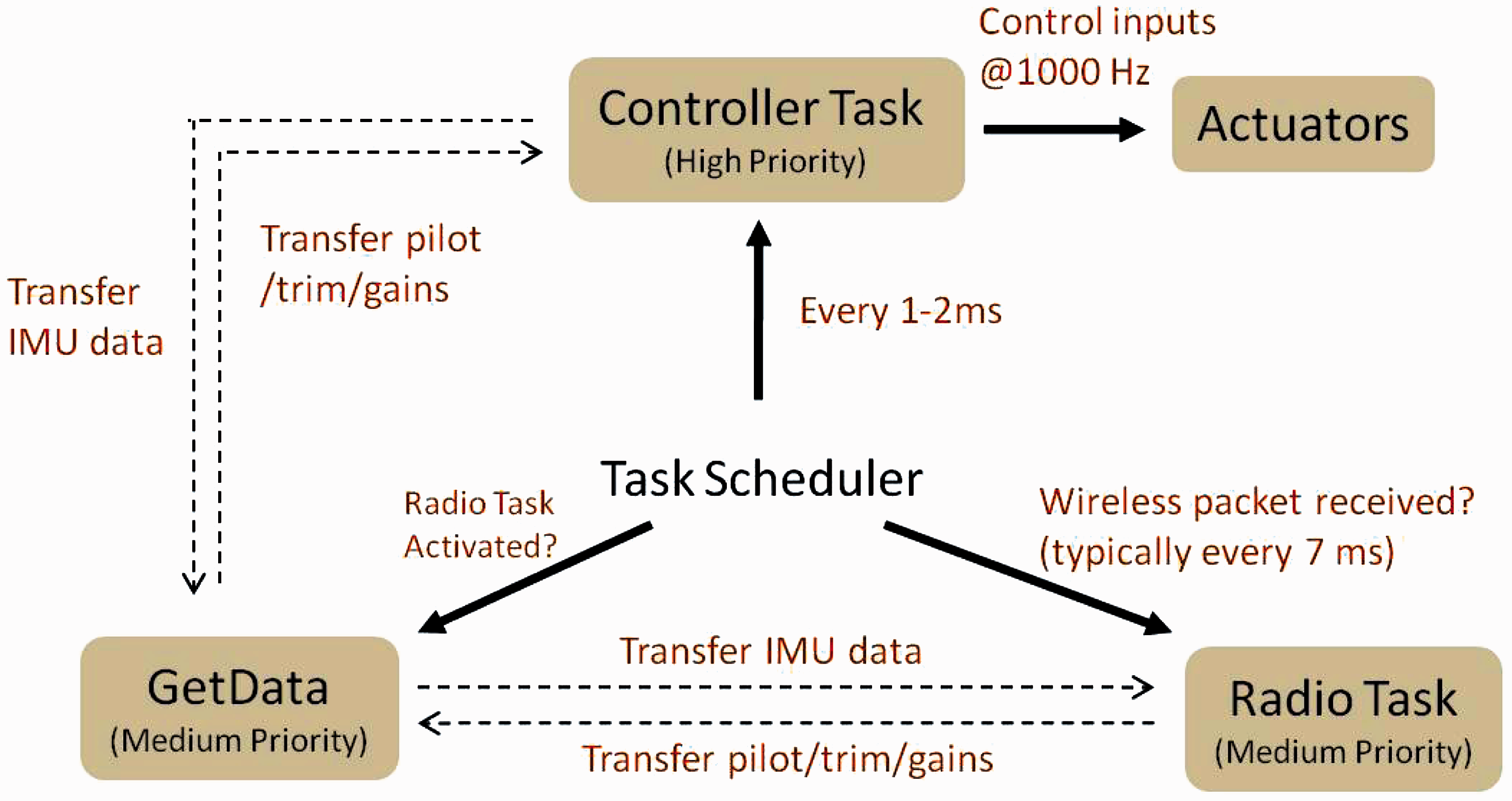
Attitude estimation and control
To stabilize and control the vehicle in hover, it is necessary to determine the pitch and roll angles in addition to obtaining the gyro and accelerometer values. One way of computing this is through Euler angles and complementary filters. However, in order to avoid singularity issues that may arise when the vehicle changes pitch attitude by 90°, a quaternion-based attitude computation is implemented in the controller module. Consider a quaternion vector of unit magnitude described by 

This error vector or objective function is optimized using a gradient descent method
15
and the solution is updated in Equation (1) for the next time step. Finally, the measured quaternions can be converted back to the familiar Euler angle representation,


In this manner, onboard attitude estimation can be accomplished for control purposes fairly accurately as shown in Figure 11. Additionally, it can be seen from Figure 12 that there is minimal drift in the estimated attitude when kept stationary for several minutes.
Comparison of pitch attitude estimates by ELKA-R with a potentiometer. Minimal drift in attitude estimation on ELKA: Step input in attitude given at t = 5 s.

Application specific feedback control algorithms can then be implemented once the basic vehicle states have been determined. For testing purposes, a simple proportional-derivative controller was applied using the attitude rates and attitude angles as feedback states. It should be noted that for the yaw DOF, feedback is carried out using the measured yaw gyro values. No integration is performed since this resulted in drift in yaw angle estimation. Additionally, correction of this drift using onboard magnetometers was not feasible. Future modifications to magnetometer positioning will be made for this to be possible.
PCB design and testing
With the basic hardware components and their communication layers established, the printed circuit board design for ELKA is described in this section. The layout of ELKA was generated using the open-source EAGLE PCB design software. 16 Two main versions of ELKA were designed using ARM Cortex-M3 and ARM Cortex-M4 processors, respectively.
Embedded lightweight kinematic autopilot
In this version, the STM32F103 microcontroller was implemented using a two-layer design approach. The signals were split into three classes with three different line widths and “via” sizes:
Standard signals: with a minimum trace width, trace spacing, and vias of 0.004″. Power signals (VCC, GND): with a minimum trace width, trace spacing, and vias of 0.008″. RF signals: with a preferable trace width of 0.032″ and vias of 0.012″.
Figure 13 shows the top copper layer (red) and the bottom copper layer (blue) of the board, respectively. Thicker tracks were used for the power lines for decreasing the possible problems associated with voltage drops and heating of the lines. The RF signals were treated carefully by keeping it on the top side of the board (red) and avoiding usage of any vias. The ground signals were placed below and around the RF key components such as the inductors and the antennas. Placement of components directly underneath the RF components was also avoided. Moreover, the three inductors were positioned 90° to each other in order to reduce the cross coupling between them.
Board Layout – ELKA. (a) Top layer and (b) Bottom layer.
The RF tracks were chosen to be 32 mils in width. This was to adapt the impedance of the RF signal between the nRF24L01 and the antenna to as close as 50 Ωs as possible. While this affects the size of the board, it is important to adapt the transmission line appropriately.
Embedded lightweight kinematic autopilot-revised
The MCU for this version was upgraded to the Cortex-M4 STM32F405 processor using a four-layer approach. The VCC and GND layers were embedded in between the top and bottom layers mainly to improve the compactness of the board. Additionally, instead of a breakout board to access the actuator signals, direct access was provided as shown in Figure 14. Both the PCBs were manufactured using the standard FR-4 material with 1 oz. copper thickness.
Board layout – ELKA-R. (a) Top layer and (b) Bottom layer.
The printed circuit board designs were fabricated and populated with components using professional assembly services within about 80 dollars/piece.
Implementation
Figure 15 shows an image of ELKA-R implemented on a representative quad rotor vehicle for hover flight control and stabilization. ELKA was implemented on a number of MAV research projects which are briefly described as follows:
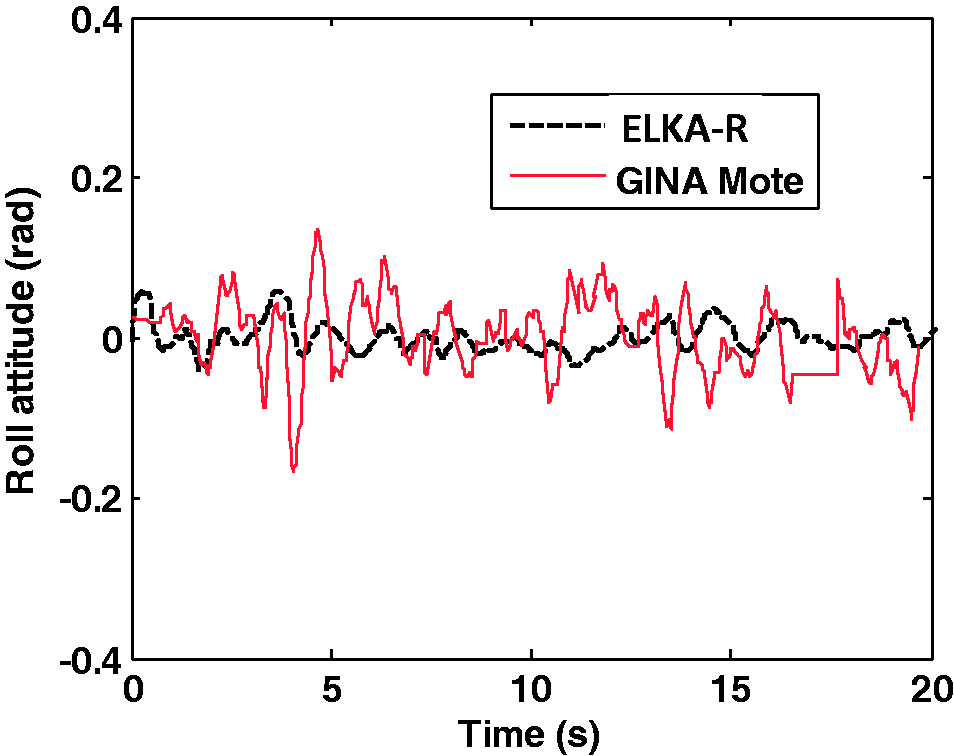
Implementation of ELKA-R on a flight vehicle showing minimal wiring required for flight operation. Implementation of ELKA-R on various micro air vehicles achieving stable hover flight. Comparison in hover flight performance of a quad shrouded rotor using GINA Mote vs ELKA-R.


Conclusions
With the advancements and requirements of microsystems such as mini-drones that can often have extremely unstable dynamics and operate in unsteady external environments, there is a need to develop low power and lightweight INS that can offer aggressive stabilization rates and can be applied to a wide variety of applications and vehicle designs. This paper discusses the design, development, and testing of one such INS called ELKA.
ELKA was designed using the powerful 32-bit ARM Cortex microprocessors as the main MCU. Two versions of ELKA were fabricated using ARM Cortex-M3 (ELKA) and Cortex-M4 (ELKA-R) processors. The MCU interfaced with the state of the art nine DOF MPU9150 IMU as well as a 2.4 GHz wireless transceiver (nRF24L01). ELKA-R could drive a wide variety of motor and actuator configurations using multiple timer configurations. ELKA was fabricated using a two-layer layout whereas a four-layer layout scheme was adopted for ELKA-R. Both of the boards weighed less than 1.7 g with an area less than 6.3 cm2, thus making them one of the smallest and lightest kinematic autopilots in open literature that can be applied to any generic MAV system.
ELKA and ELKA-R were also tested on a variety of MAV flight demonstrators. Hover stabilization rates of 1000 Hz were achieved and flight oscillations were reduced by up to 50% when compared with a previous generation autopilot.
All of the design procedures involving hardware and software for the development of ELKA were completed using open-source tools. Using these, other research groups can easily modify existing designs so that more powerful hardware and software changes can be implemented in the future.
Footnotes
Declaration of conflicting interests
The author(s) declared no potential conflicts of interest with respect to the research, authorship, and/or publication of this article.
Funding
The author(s) received no financial support for the research, authorship, and/or publication of this article.