
Abstract
The use of electrostatic fields to control the location of charged fuel droplets in a spray jet flame is investigated as a means of developing fuel-flexible combustion systems to accelerate the transition to carbon-neutral transportation. The focus of this work is on the effects of an external electric field parallel to the jet direction on the spray penetration and fuel vapour distribution, and the subsequent effects on flame shape and location. This study is conducted using large-eddy simulations under the assumption that there is negligible production of charged species during combustion. Non-reacting simulations at atmospheric conditions show that with practical electrostatic fields and droplet charges, it is possible to significantly change the spray penetration. Electric forces in the opposite direction to the spray jet lead to a reduction in the spray penetration, an effect that increases with stronger electrostatic fields. This leads to an increase in drag between the droplets and the air flow, resulting in a smaller penetration of the air jet. The reduced droplet penetration confines the fuel vapour to a region closer to the jet inlet and leads to a more compact flame in the corresponding reacting cases. Similar trends are observed in simulations performed at a higher pressure and temperature. This study suggests that electrostatic fields can be used with charged fuel droplets to provide an element of control over spray jet flames, which may allow for the development of novel hybrid thermal–electric combustion systems.
Keywords
Introduction
An urgent transition to a zero-carbon energy infrastructure is needed to reduce the impact of human activities on the concentration of carbon dioxide in the atmosphere and on climate change. An analysis of carbon dioxide emissions by sector highlights that the transportation sector is responsible for a significant portion of global carbon dioxide emissions, approximately 23% in 2023 with aviation constituting over 10% of these emissions. 1 Additionally, estimates from pre-pandemic data indicate that aviation accounts for around 5% of human-induced global warming. 2 Decarbonising the transportation sector is therefore essential and requires the use of alternative energy vectors, including batteries and zero-carbon fuels, as well as the development of new technologies for their safe and efficient use. Although progress towards a zero-carbon economy has been made for both power generation, for example, through the development of technologies for zero-carbon fuels, 3 and land transportation, with electrification being the main solution to abate carbon emissions, 4 challenges still remain for the aviation sector. In particular, the specific energy density of the latest battery technology is insufficient to allow for all-electric long-haul flights. 5 Furthermore, the necessity of keeping the weight and size of the aircraft down, together with safety considerations, makes the use of zero-carbon fuels such as hydrogen challenging. Therefore, it is not surprising that the main engine and aircraft manufacturers are currently looking at hybrid thermal–electric propulsion configurations 6 coupled with sustainable aviation fuels (SAFs) as a medium-term solution to lower the carbon footprint of aviation. The use of hybrid thermal–electric propulsion systems will lead to a large availability of electrical energy on board, which could offer new possibilities to achieve control over the combustion process and to extend the range of fuels used in aviation. 7 In this context, technologies that make use of electrical energy to improve mixing8,9 and combustion characteristics 10 have been proposed.
In general, the behaviour of a combustion system used in aviation is very sensitive to the type of fuel. In most cases, an injection system and a combustor designed to work for a given fuel lose performance (e.g. lower atomisation quality and higher emissions at the exhaust) when operated with fuels with significantly different properties. Consequently, SAFs are typically designed with thermophysical properties that replicate the properties of conventional jet fuel so that they can be used in existing combustion technologies.7,11 However, this may exclude some fuels that have good properties from an environmental standpoint because the combustor design is not suitable for their use. From this perspective, it would be ideal to have a fuel-flexible combustor, that is, a combustor that can operate well with fuels characterised by a wide range of properties. By taking advantage of the electrical energy available on board in hybrid configurations, Fredrich et al.
8
proposed the combination of charge injection atomisation and electrostatic control of droplet trajectories to achieve fuel pre-evaporation in a compact space. Considering the same technology, Giusti and Fredrich
12
further investigated the possibility of pre-evaporating fuels characterised by different properties, such as
The possibility of using electric fields to control combustion is not limited to the modulation of mixing of charged fuel droplets. Electric fields can also be used to directly affect flame characteristics. Over the years, many studies, mainly experimental, have demonstrated that both AC and DC electric fields can influence emissions, change the shape of flames and allow for the control of combustion instabilities.13–17 The macroscopic effect of electric fields observed in those investigations is mainly due to the action of the electric field on charged species that form during the combustion process, leading to an ionic wind. 18 In the context of spray flames with no applied electric field, recent studies have shown that the presence of charged droplets can affect the local flame structure. 19 However, the combination of an external electrostatic field and charged droplets in a reacting environment has not been investigated yet. In this case, the applied electrostatic field is expected to affect both the positions of the fuel droplets, which influences the mixing of fuel vapour with the surrounding gaseous mixture, and the transport of ionic species. The combination of these effects will change the flame characteristics.
The aim of this work is to investigate the use of electrostatic fields to manipulate the location of fuel in a spray jet flame containing charged fuel droplets, a configuration of practical interest for both power generation and transportation, and to evaluate the subsequent effects on mixing and the reactive field. The specific objectives of this work are (i) to investigate the effect of an electric field parallel to the jet axis on the location of charged droplets under non-reacting conditions and (ii) to study the spray penetration, vapour distribution and flame location under reacting conditions for different strengths of the external electric field and different pressure conditions. The investigation is performed using large-eddy simulations under the assumption that there is negligible formation of charged species during the combustion process. This assumption means that electric field effects on the transport of ionic species and electrons generated by the combustion process are not accounted for, which allows for a first assessment of electric field effects on the mixing and reacting field due solely to the modulation of droplet locations. The combined effect of an electric field on the spray and on ionic species and electrons formed in the reacting region should be investigated in future work.
Methods
Configuration
The spray jet flame schematically shown in Figure 1 is investigated. The configuration is similar to the piloted spray flame investigated at the University of Sydney. 20 The spray, generated upstream of the burner, is injected together with an air flow through a central duct of diameter 7.5 mm, referred to as the spray inlet. This duct is surrounded by a concentric flow, called the pilot flow, that under reacting conditions enables the injection of hot combustion products to stabilise the flame. The pilot flow is surrounded by a co-flow of air. In the configuration investigated in this study, the co-flow extends over the remainder of the bottom boundary of the domain. In experimental set-ups, however, the co-flow is often injected through a smaller annular duct.
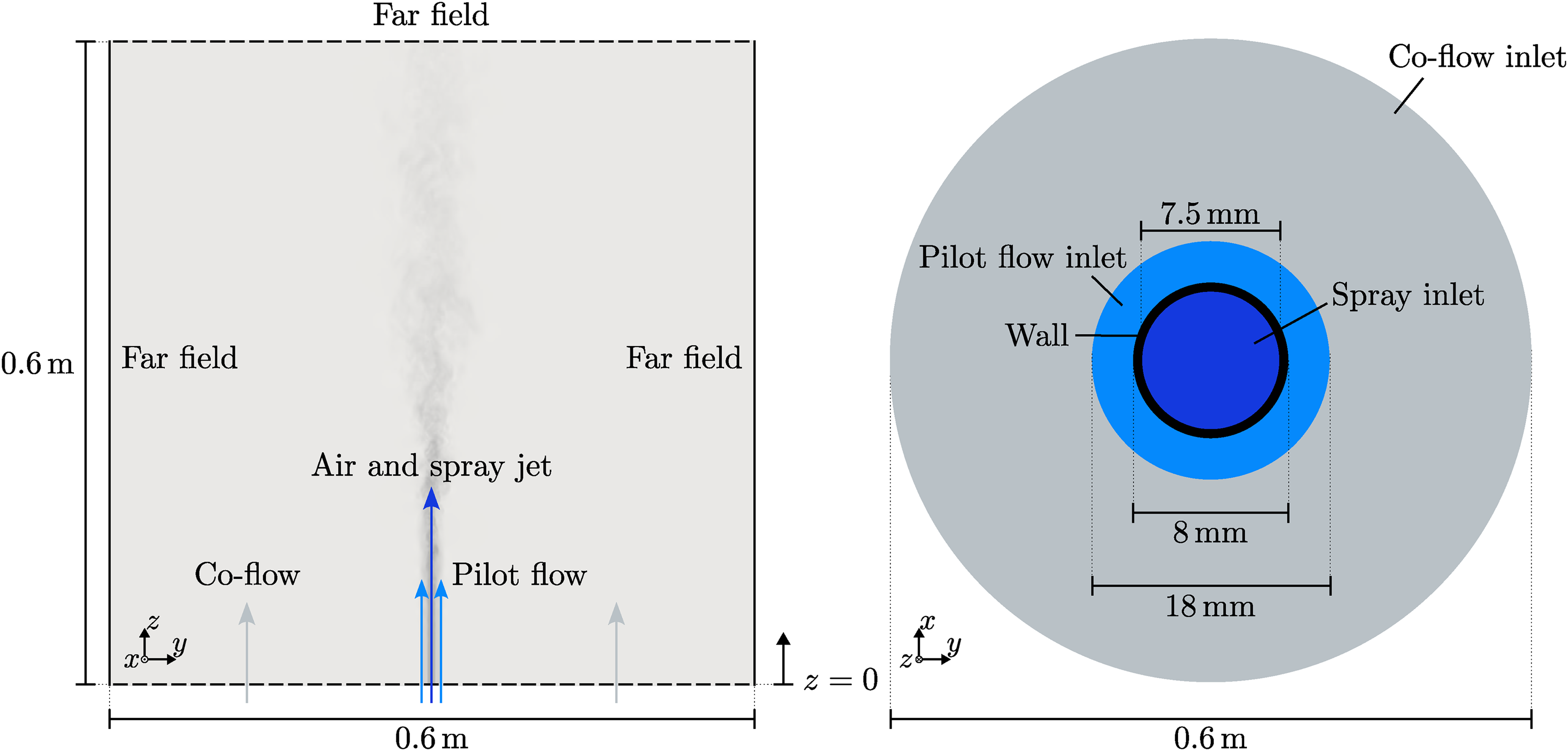
A schematic of the configuration investigated in the present work, which indicates the dimensions of the domain used for large-eddy simulations. A vertical cross-section of the domain is shown on the left; the inlet flows are shown on the right.
The electric field is generated by applying a potential difference between two planar electrodes with normal parallel to the axis of the spray duct (the
Investigated cases
The effects of an electrostatic field on the spray and flow dynamics are investigated under both non-reacting and reacting conditions. The non-reacting (‘cold-flow’) cases allow the effects of an applied electric field on the trajectory of droplets and spray jet dynamics to be studied without the additional complexity of chemical reactions. The reacting cases build on the knowledge developed from the cold-flow conditions and reveal how modifying droplet trajectories using an electric field affects the fuel vapour distribution and flame characteristics. Cold-flow simulations are performed at a pressure of 1 bar, with air injected through all inlets at a temperature of 293 K. For the reacting cases, two pressures are investigated,
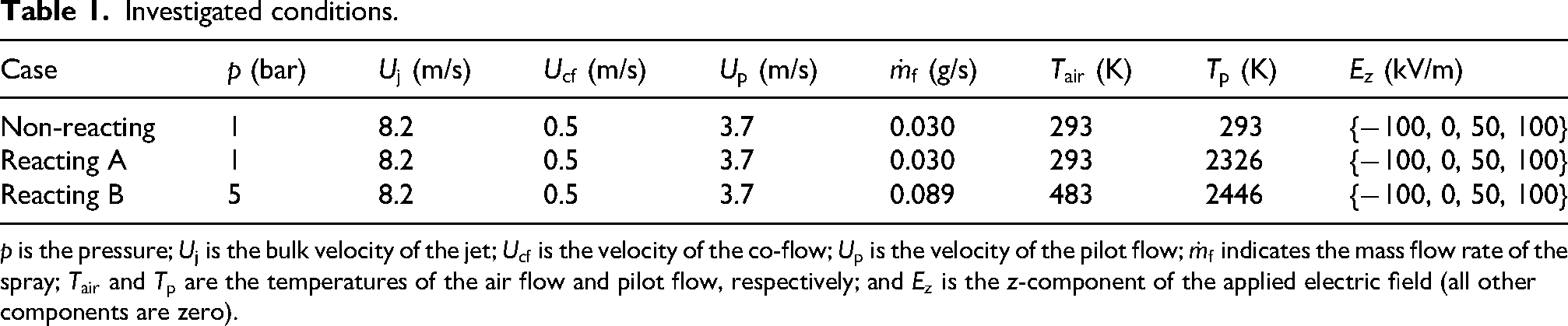
Investigated conditions.
Large-eddy simulations
Simulations are performed with the large-eddy simulation approach and a two-way coupled Eulerian–Lagrangian method for dilute sprays. The solver, implemented in OpenFOAM-v7, 25 is the same as used in previous work 8 with the addition of chemical source terms for the gaseous phase and combustion modelling. The charged fuel droplets are modelled as point Lagrangian particles with gravity, drag and electric forces acting on them; all other forces are neglected. A drag force relation for spherical droplets is adopted. 9 Local variations of the electrostatic potential due to the presence of charged droplets and Coulomb repulsion between the charged droplets are neglected. Therefore, the electric force acting on the droplets is simply computed as the product of the droplet charge and the external electric field. Secondary atomisation, including droplet breakup induced by electrostatic repulsion between the charges inside each droplet,21,26 is not accounted for in the present work. Secondary breakup models that account for droplet deformation and the charge distribution within each droplet under an external electric field should be developed in the future. 21 The presence of charges within the droplets is assumed not to affect the evaporation process. 27 In addition, it is assumed that the charge of each droplet stays constant during the entire evaporation process. 28 Under cold-flow conditions, the evaporation time of the droplets (approximately 5.1 s, computed with single-droplet simulations using the methodology discussed in Fredrich and Giusti 29 ) is much larger than the simulated time. Therefore, non-evaporating droplets are used in the cold-flow simulations. In the reacting simulations, evaporation is modelled using a rapid mixing model with the Ranz–Marshall heat transfer correlation. 30 Furthermore, combustion is modelled with infinitely fast chemistry and a single-step chemical mechanism, with water and carbon dioxide being the only combustion products. This simple modelling approach is sufficient to provide an estimate of the flame location, which is the focus of this work. The mechanism used does not include the formation of charged species, such as ionic species, charged radicals and free electrons; therefore, it is not possible to capture the influence of the applied electric field on the transport of gaseous species or related ionic wind effects.31,32 An extensive investigation of the flame structure using a more comprehensive combustion model and a detailed chemical mechanism that includes the formation of charged species should be performed in future work. This will allow for a complete assessment of electric field effects on the flame structure and pollutant formation, as well as an examination of electric field effects on flame behaviour under extreme conditions, such as flame extinction and re-ignition. Depending on the chosen combustion model and simulation framework, closure of terms in the transport equations representing sub-grid effects of the electric field may be necessary.
Numerical set-up
The numerical domain, shown in Figure 1, is a cylindrical geometry concentric with the axis of the spray duct, with the lower boundary located at the exit of the spray jet. The velocity of the air flow entering through the spray inlet is modelled with a power-law profile (
Results
The velocity field and spray location obtained with cold-flow simulations are first presented to assess electric field effects in the absence of a flame. Then, reacting conditions are analysed with a focus on the fuel vapour distribution and the flame location.
Cold-flow simulations
Figure 2 shows a snapshot of the spray and the

The
The effect of the droplets on the air flow was also investigated. Considering the cases with an applied electric field in the positive
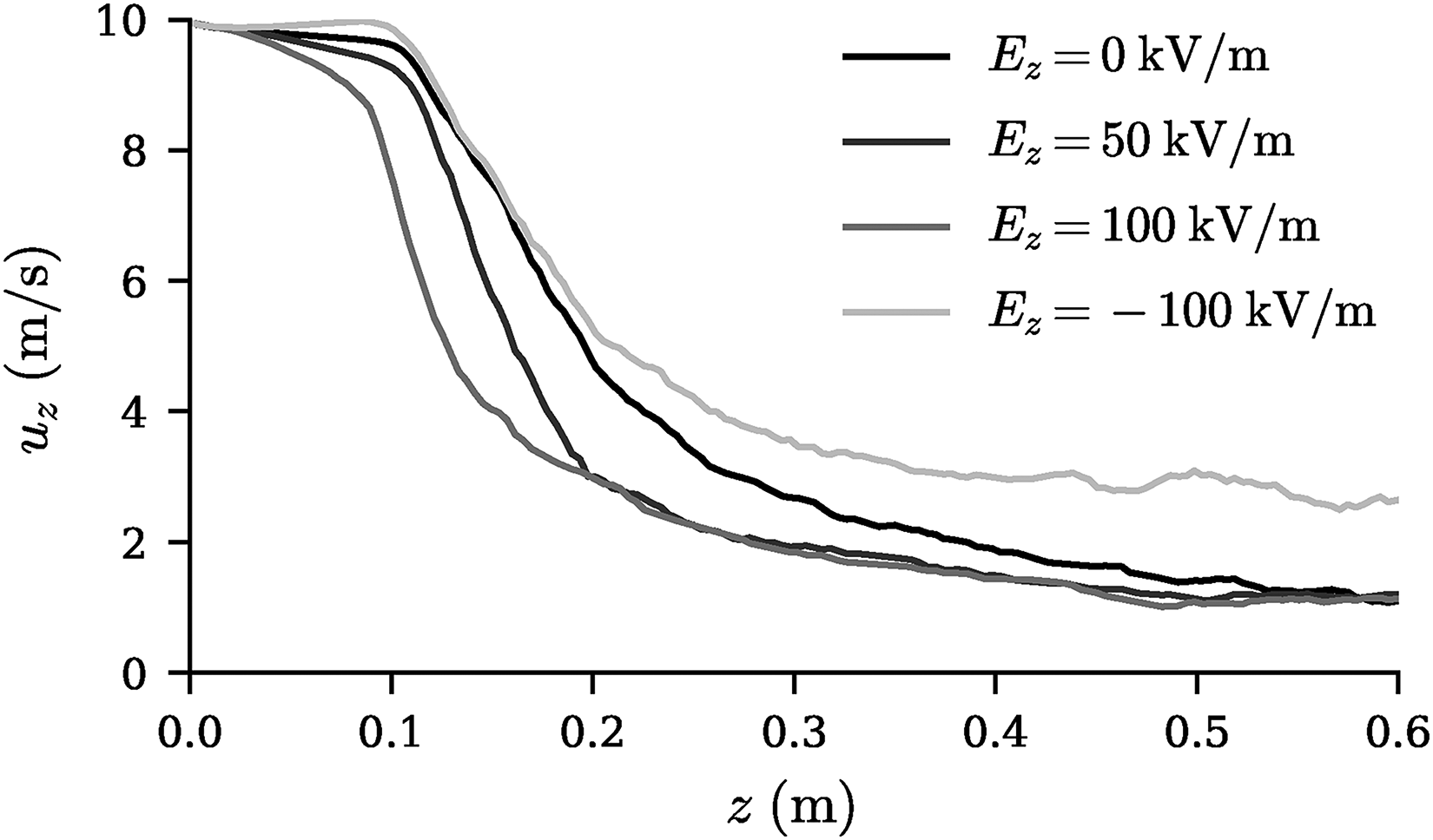
The time-averaged
Flame simulations
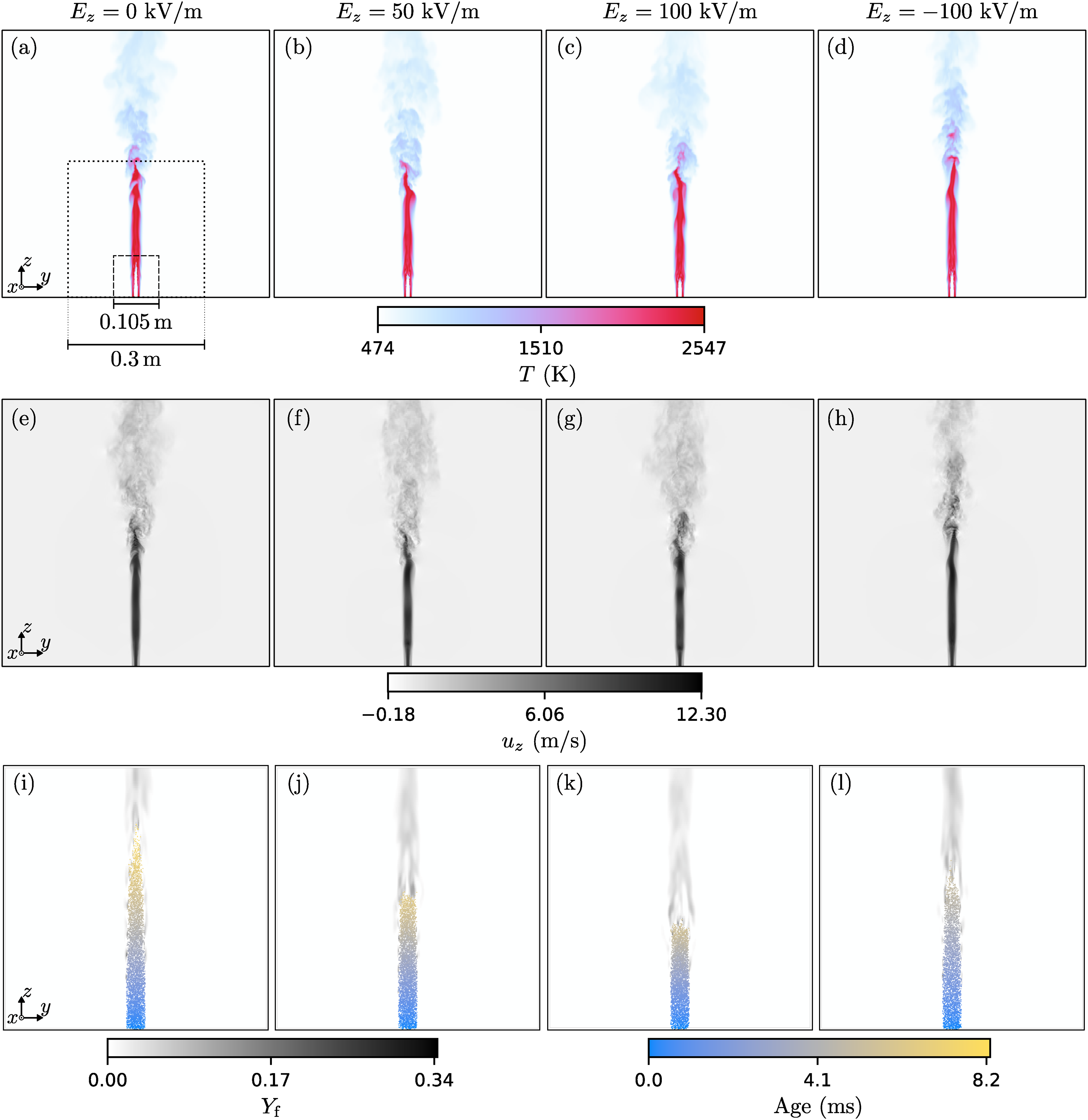
Snapshots of the temperature and
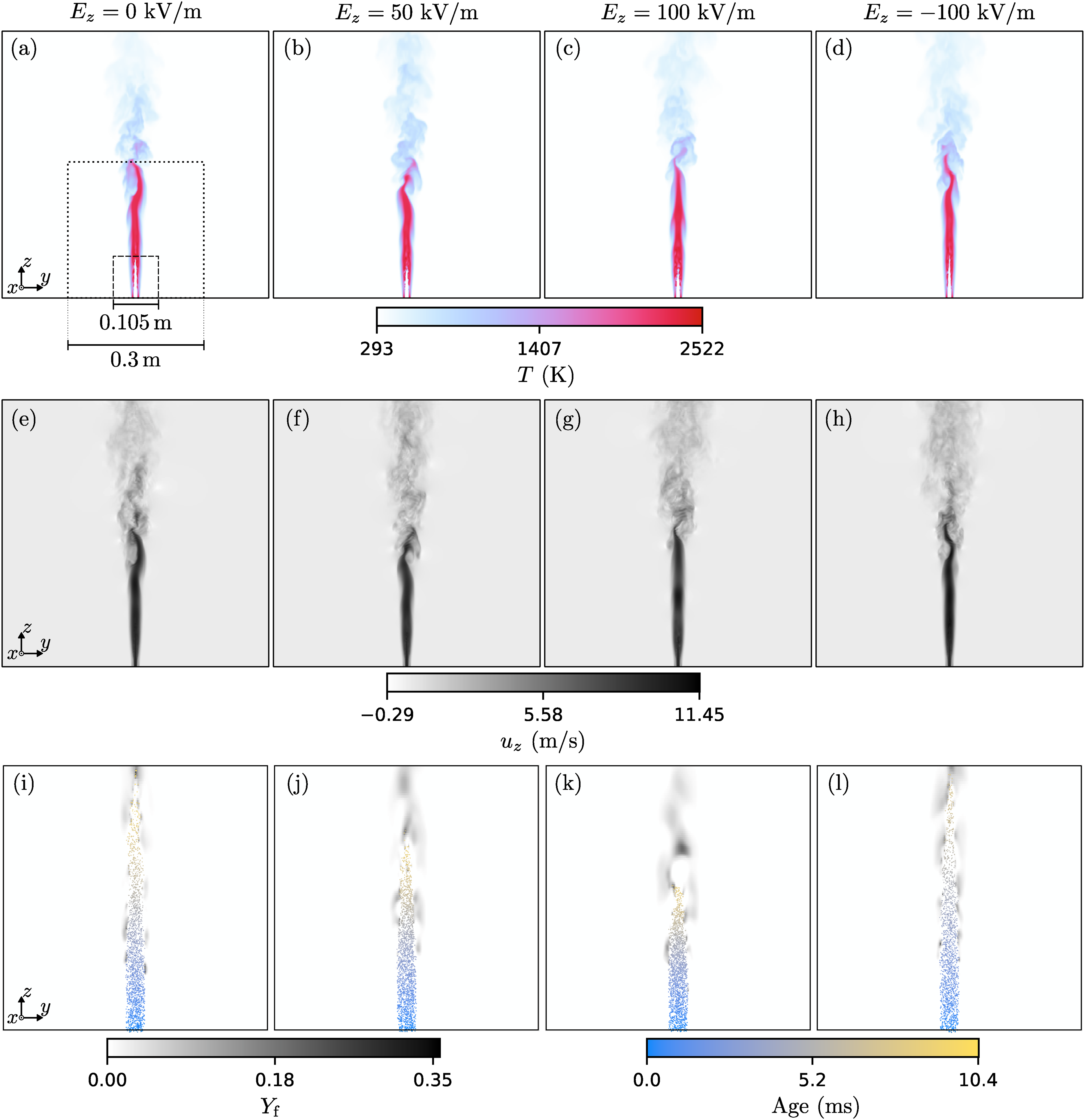
The temperature (a–d),
The change in penetration of the spray affects the location of fuel vapour release, altering the extent of the reacting region. This is shown in Figure 5 for

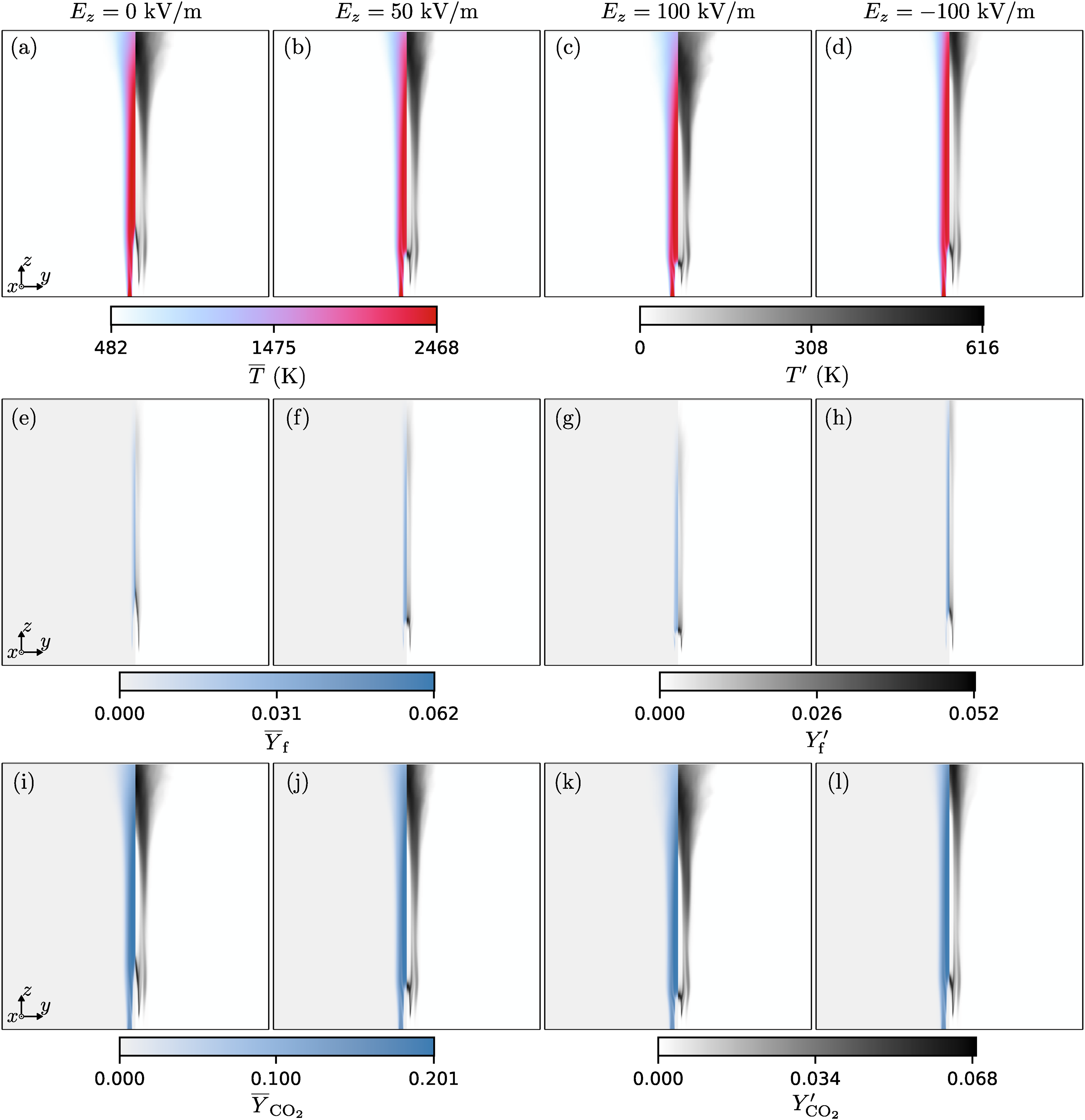
The time-averaged statistics of the temperature (a–d), the mass fraction of fuel (e–h) and the mass fraction of
Figures 6 and 7 present the instantaneous and time-averaged results for the cases at
The temperature (a–d),
The time-averaged statistics of the temperature (a–d), the mass fraction of fuel (e–h) and the mass fraction of
The droplet dynamics are further analysed in Figure 8, which shows the normalised droplet count, the average diameter and the average axial droplet velocity as a function of the distance from the injection location for the two pressures and the different electric fields investigated in this work. The normalised droplet counts (see Figure 8(a) to (d)) provide further evidence of the reduced penetration of the spray with increasing operating pressure. It is also evident that the spray penetration falls with increasing
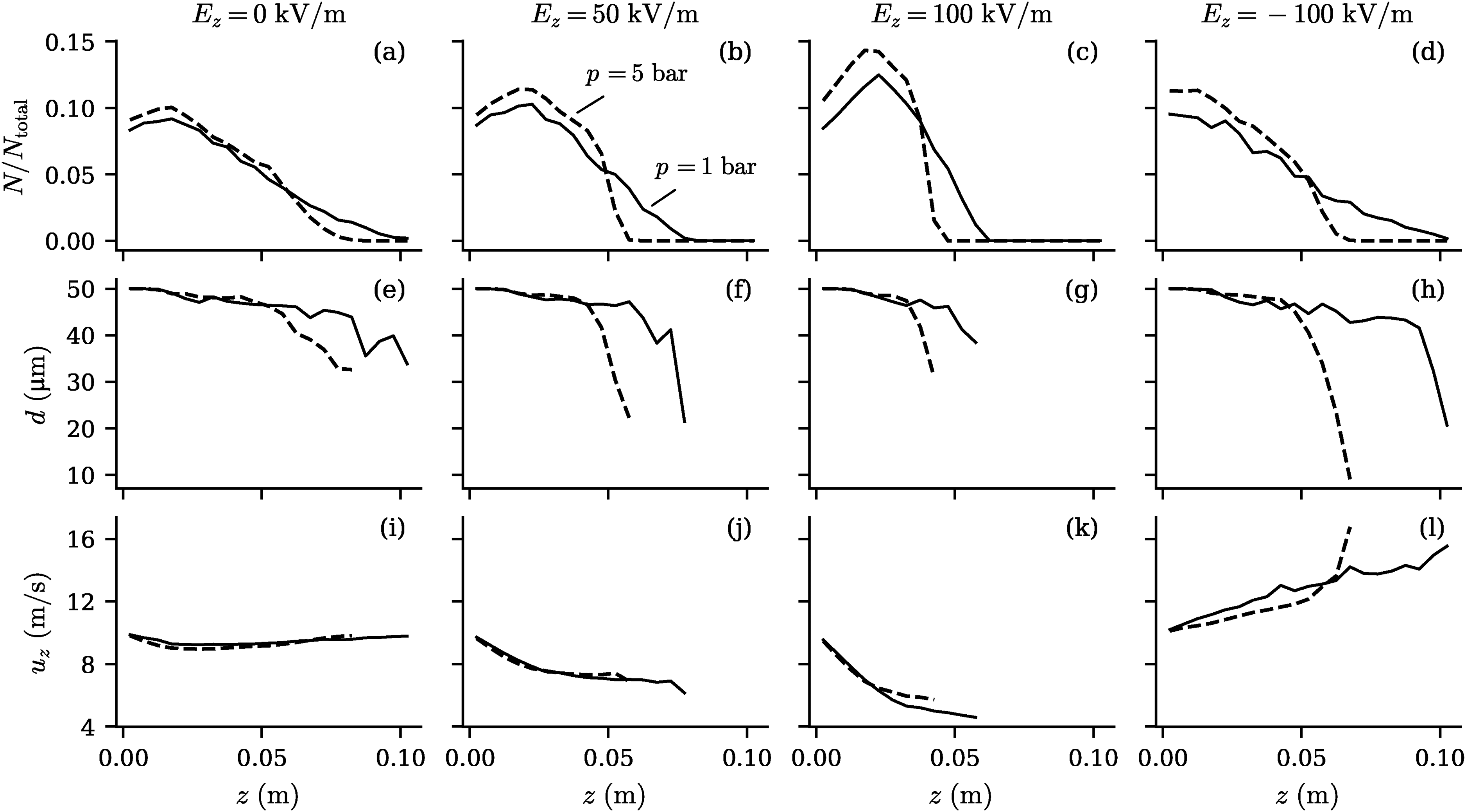
The droplet counts normalised by the total number of droplets in the system (a–d), the droplet diameters (e–h) and the
Discussion
The present investigation demonstrates that with realistic electric fields, that is, electric fields with strength significantly below the dielectric strength of air (
A monodisperse spray with the same charge for all droplets has been considered in this work. The presence of a polydisperse spray with a relatively wide droplet size distribution, together with differences in the charge of each droplet, may make it more challenging to control the penetration of the spray and where the fuel vapour is released. This is because the diameters and charges of the droplets impact the drag and electric forces acting on the droplets, which determine the penetration of the spray. In addition, charge-induced secondary breakup may lead to a significant redistribution of charge from a given droplet to smaller child droplets, 34 causing further dispersion of the droplet size and charge distributions. Therefore, the control of sprays characterised by a dispersion of diameters and charges should be investigated in future work, while also accounting for charge-induced secondary breakup. 21 This first requires a more comprehensive characterisation of the sprays produced by charge injection atomisers. Furthermore, this study did not account for repulsive Coulombic interactions between the charged fuel droplets, which may affect the flame shape by increasing the dispersion of the spray. Further work is necessary to accurately model and characterise the effects of electrostatic interactions between the droplets.
The ability to modulate the spray location is strongly dependent on the spray jet bulk velocity. To counterbalance drag forces with electric forces while keeping the required electric field strength below the dielectric strength of air, relatively low jet velocities must be employed. In addition, evaporation occurs significantly faster when increasing the operating pressure from 1 to 5 bar due to the larger air and pilot flow temperatures. Since faster evaporation limits the time available to modify the trajectories of droplets, stronger electric fields will likely be needed to induce significant changes in the spray penetration as the evaporation time is reduced. An alternative would be to inject droplets with a larger diameter to increase their evaporation time. This strategy should be investigated in future research. Additionally, the uniform electric field investigated in this study would be difficult to achieve inside a realistic combustor. Consequently, future studies should move towards the investigation of configurations of practical interest, which may also involve pressures greater than 5 bar when considering medium- to large-sized gas turbine systems.
It should be re-iterated that the chemical mechanism used in the present study does not include the formation of charged species and free electrons. However, there is strong evidence that the combustion of hydrocarbons leads to substantial formation of ionic species.17,32 The movement of charged gaseous species under an electric field and their collisions with neutral species could generate a relatively strong flow, known as ionic wind, which could further affect the flame shape. Integration of a detailed chemical mechanism that includes free electrons and ionic species,31,32 as well as the development of a large-eddy simulation framework with closure of sub-grid scale terms representing the effects of species drift driven by an electric field, are part of current research. In addition, combustion was modelled in this study with a simple single-step mechanism and with infinitely fast chemistry. The study of pollutant formation and the effects of electric fields on the local flame structure necessarily requires the use of more detailed chemical mechanisms. Furthermore, the investigation of spray flames with a higher level of turbulence will require the use of more advanced combustion models. 35 Finally, experiments in canonical configurations such as the one studied in this work should be conducted in the future to provide experimental evidence of electric field effects on spray flames with charged droplets and to support the validation of modelling frameworks.
Concluding remarks
The use of electrostatic forcing to modulate the penetration of charged fuel droplets in a spray jet flame configuration and the subsequent effects on the fuel vapour distribution and the flame shape have been investigated using large-eddy simulations. The results demonstrate that realistic electric fields with strengths of the order of 100 kV/m can provide an element of control over droplet trajectories. When the applied electric field exerts a force on the charged droplets in the opposite direction to the spray jet flow, the penetration of the spray decreases with increasing strength of the electric field. This results in a more compact reacting region that moves closer to the spray inlet. Electric forces in the same direction as the spray jet flow tend to move the droplets away from the spray inlet, an effect that is very evident under cold-flow conditions. This, however, does not necessarily result in flame elongation. An increase in the operating pressure reduces spray penetration and makes the flame more compact, with the applied electric field leading to similar effects on the spray penetration and position of the reacting region as compared to atmospheric conditions. The present investigation provides evidence that electrostatic fields have the potential of assisting fuel preparation by reducing the space necessary for full evaporation, an effect that could be used to build compact combustors with fuel flexibility enabled by modulating the strength of applied electric fields.
Footnotes
Acknowledgements
The authors acknowledge the Imperial College Research Computing Service (doi.org/10.14469/hpc/2232) for computational resources. The authors also thank William A. Lilleland and Francesco Merloni for the work they conducted on the spray jet flame configuration in their Master’s projects.
Funding
The authors disclosed receipt of the following financial support for the research, authorship, and/or publication of this article: This work was performed within the framework of the FFLECS Project funded by the European Unions Horizon Europe research and innovation programme under Grant Agreement No. 101096436. Views and opinions expressed are however those of the authors only and do not necessarily reflect those of the European Union. Neither the European Union nor the granting authority can be held responsible for them. UK participants in Horizon Europe Project FFLECS are supported by UKRI grant numbers 10101902 (Imperial College London) and 10085576 (University of Cambridge).
Declaration of conflicting interests
The authors declare no potential conflicts of interest with respect to research, authorship, and publication of this article.