
Abstract
This study examines the dynamics of diesel/hydrogen dual-fuel combustion in a constant-volume vessel under compression ignition engine conditions, where a small pilot n-heptane (a surrogate of diesel) injection precedes a long-duration hydrogen main injection containing 93.6% of the energy share. We investigate how pilot n-heptane flame and hydrogen injection affect emissions and combustion by systematically varying the dwell time (
Highlights
Ignition consistently initiates near Dwell-time strongly influences ignition delay and flame development pathways. Large eddy simulation reveals mixing-controlled ignition propagation into hydrogen-richer zones. NO
Introduction
Hydrogen (H
However, the advantages of using hydrogen in ICE come with several technical challenges that hinder its widespread adoption. Hydrogen’s high auto-ignition temperature allows for the use of higher compression ratios, potentially improving thermal efficiency. At the same time, its low ignition energy, while beneficial for lean combustion, also increases the risk of premature ignition caused by hot spots or residual gases in the combustion chamber. 7 Moreover, the relatively high auto-ignition temperature of hydrogen (858 K) often requires the use of ignition aids if increasing the compression ratio is not a feasible solution. Additionally, the physical properties of hydrogen, particularly its low density, pose significant challenges for storage and injection into the combustion chamber. Addressing these challenges requires further technological advancements and research to realize hydrogen’s potential as a fuel for ICEs.
Internal combustion engines predominantly utilize two methods of fuel injection: port fuel injection (PFI) and direct injection (DI). PFI involves injecting fuel into the intake port and mixing it with air before entering the combustion chamber. This method allows for significant air–fuel mixing early in the compression cycle, resulting in homogeneous fuel/air mixtures with controlled equivalence ratios. However, when hydrogen is injected using PFI, its low density displaces a considerable air volume during the intake valve opening period, reducing volumetric efficiency. 8 Additionally, PFI increases the risk of knocking or premature ignition in a premixed or partially premixed hydrogen/air mixture due to exposure to hot spots within the chamber.
In contrast, DI techniques inject fuel directly into the combustion chamber and avoid the drawbacks associated with volumetric efficiency loss and premature ignition. DI is subdivided into high-pressure direct injection (HPDI) and low-pressure direct injection (LPDI) strategies based on the rail pressure used. Injection pressure below 50 bar classify an injection system as LPDI, which typically necessitates to inject the fuel early in the cycle, before cylinder pressure becomes too high to overcome, and thus favors premixed combustion mode. On the other hand, HPDI systems, operating above 50 bar, permit fuel injection at various stages throughout the cycle, including late injection near the top dead center, offering greater flexibility and efficiency. 9
In HPDI systems, hydrogen’s low density combined with high injection pressures can lead to complex fluid dynamic phenomena such as the formation of shock-waves at the injector nozzle outlet. The presence and characteristics of these shock-waves are greatly influenced by the ratio of injection pressure to back pressure within the combustion chamber. 10 Experimental investigations have shown that these dynamics are critical for understanding how hydrogen behaves under actual engine conditions. For instance, previous studies have detailed how shock-waves can significantly affect the dispersion and hydrogen mixture in the chamber, 11 which could impact efficiency and emission profiles. Dauptain et al. 12 explored the behavior of supersonic hydrogen flows, demonstrating how shockwave patterns change with varying pressure ratios. These phenomena have been extensively studied through numerical simulations, particularly employing large eddy simulation (LES).13,14
Reacting hydrogen jets under high-pressure conditions introduce additional complexities, particularly regarding ignition and flame stabilization. These processes are highly sensitive to variations in ambient conditions, such as oxygen concentration and temperature, which directly influence flame dynamics and ignition characteristics. While less extensively studied compared to non-reactive jet behavior, reacting cases present unique challenges and phenomena that are critical for practical applications. Roy et al.
15
explored the ignition processes by directly injecting a hydrogen jet and igniting it with a spark in a constant volume chamber. Subsequently, more advanced ignition methods have been employed, such as using a laser to initiate combustion under engine-like conditions. It was revealed that the key phenomenon governing flame regression towards the nozzle is the edge-flame deflagration, which is highly dependent on the concentration of ambient oxygen.
16
Naber and Siebers
17
reported that the combustion rate appeared insensitive to changes in oxygen concentration during the mixing-controlled phase of hydrogen jet combustion. Further studies, such as those by Yip et al.,
18
focused on the auto-ignition of hydrogen in constant volume vessels resembling compression ignition engine conditions, where ignition typically starts at a single kernel and subsequently engulfs the jet. These studies show that the lift-off length varies with oxygen concentration, extending significantly at lower levels (10 vol.% O
The hydrogen’s high auto-ignition temperature necessitates innovative strategies for efficient ignition in compression ignition (CI) engines. Dual-fuel strategies, which utilize a fuel with a higher cetane number, like diesel in a pilot injection to initiate the combustion process, offer a practical solution to this problem. Such strategies enhance ignition reliability and overall engine efficiency.19–23 For example, White 21 investigated diesel-natural gas dual-fuel configurations using both experimental and numerical methods, finding that converging injector configurations offer better combustion characteristics than parallel configurations. This finding was further supported by experiments conducted in a rapid compression machine, which showed that diesel-natural gas mixtures benefited from converging injector configurations.22,23 Specifically, stronger interaction between the hydrogen jet and the pilot plume enhances local mixing and thermal coupling, which accelerates the onset of ignition in the hydrogen-rich region and minimizes the extent of premixing. Additionally, these studies observed that the strong interaction between the two fuels could occasionally result in flame quenching, underscoring the delicate balance required in dual-fuel combustion dynamics.
A recent publication experimentally investigated diesel-hydrogen dual-fuel strategies in a constant volume vessel, focusing on varying the injection order between diesel-pilot and hydrogen-main, alongside modifications in ambient conditions and dwell times. 24 Unlike experiments with natural gas, these studies did not report quenching effects with hydrogen, indicating a more stable interaction between hydrogen and diesel. It was also observed that increasing the dwell time required prolonged exposure to the diesel flame to achieve successful hydrogen ignition. In related research, 25 adjustments to the energy share of diesel and hydrogen were explored, with hydrogen injected first to ensure thorough mixing with air before ignition by diesel. They reported a significant reduction in the hydrogen flame lift-off length, approaching near-zero except in cases of low ambient oxygen concentration.
These studies suggest that the understanding of the interplay between fuel interaction dynamics, mixture heterogeneity, and flame behavior under various operational settings can significantly guide the development of more efficient and cleaner dual-fuel combustion systems. However, at low temperatures, the variability of hydrogen ignition—owing to flammability limits, ignition energy requirements, and mixing quality—remains a key challenge, showing the importance of injection sequence and dwell time in dual-fuel CI strategies. A well-timed injection sequence that promotes adequate mixing while preventing excessive cooling or dilution of the combustion zone can lead to more efficient combustion and better fuel utilization.
LESs of pure hydrogen jets have been reported in the literature. The work of Hamzehloo and Aleiferis 14 investigated the effect of the nozzle pressure ratio on under-expanded hydrogen jets in internal combustion engine applications, studying the interplay between compressibility effects and near-nozzle mixing. Ali et al. 26 examined the oscillation modes of Mach disks and their influence on turbulent transition using a density-based, low-dissipation finite-volume solver. Ballatore and van Oijen 27 performed LES with a pressure-based solver and a WALE subgrid-scale model combined with fourth-order cubic convective schemes, successfully capturing the mixing behavior of under-expanded hydrogen jets in a constant-volume combustion chamber (CVCC). In a subsequent study, Ballatore et al. 28 developed an HR-FGM chemistry tabulation approach capable of accurately predicting ignition delay, kernel location, and flame stabilization. Their results suggested that hydrogen flame recession toward the nozzle may be driven by a sequence of auto-ignition events. The HR-FGM framework was further extended to hydrogen–argon–oxygen mixtures under systematically varied ambient pressure and temperature conditions. 29
A related numerical study on dual-fuel heptane-hydrogen HPDI in a CVCC was conducted by Lucchini et al. 30 Using the same experimental configuration considered in the present work, 24 they performed RANS simulations aimed at calibrating an FGM approach for subsequent application in engine simulations and accelerated optimization. To the authors’ knowledge, no LES studies of dual-fuel heptane-hydrogen combustion in a CVCC configuration have been reported to date.
The primary objective of this work is to use high-fidelity LESs to enhance understanding of the interaction dynamics between diesel flame and hydrogen jet under dual-fuel HPDI CI engine conditions. This study builds upon the experimental findings of Rorimpandey et al., 24 specifically examining scenarios where diesel pilot injections precede hydrogen injections. The focus will be on three distinct cases, differentiated solely by their dwell times, as documented in the referenced experiments. 24 Through the use of LES, this research aims to deepen the understanding of the mixing and ignition processes of these two fuels, providing detailed insights into the complex mechanisms of hydrogen jet ignition that are not evident from experimental observations alone.
Experiment specifications
In the experiments carried out at UNSW,
24
an n-heptane “pilot” (C
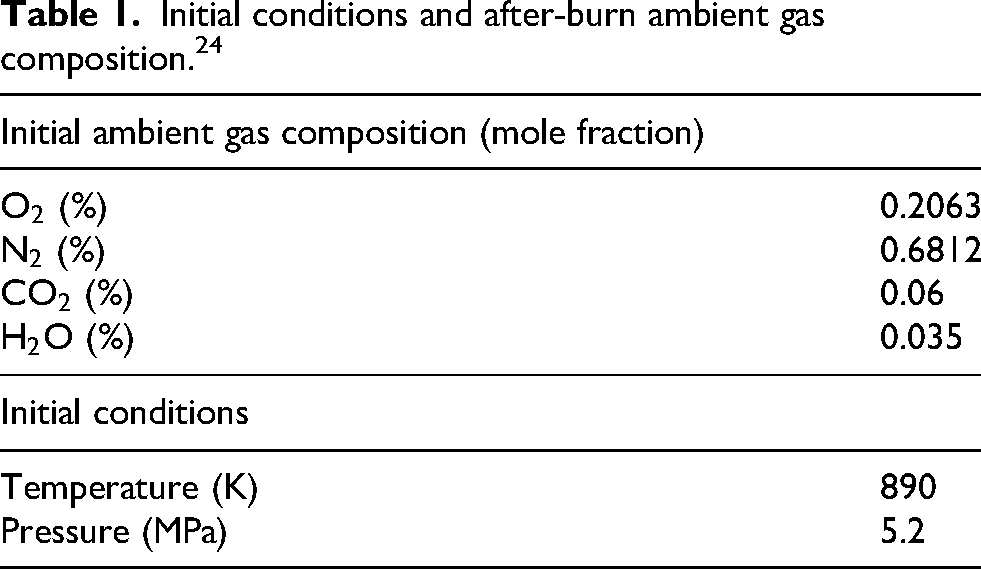
Additionally, chamber pressure is measured with a pressure transducer, and temperature is acquired at the geometrical center of the chamber with a thin-wire K-type thermocouple. To recreate the relevant conditions for CI engines, an initial mixture of air, acetylene (C
Initial conditions and after-burn ambient gas composition. 24
The injection parameters, including fuel mass, injection pressure, and duration, are kept constant in each condition. In this work, we only consider three “pilot first” cases, varying in time between the injections. Specifically 0.93, 1.93, and 2.93 ms have been selected. Time t = 0 denotes the start of n-heptane injection. For clarity, throughout, after start of injection (aSOI) refers to the time after the diesel start of injection (SOI). Table 2 shows the injection parameters and the three cases studied. The wall temperature was kept at a constant value of 403 K, to prevent water condensation during the experiment.
Injection details for both fuels and case setup extracted from the experimental measurement. 24
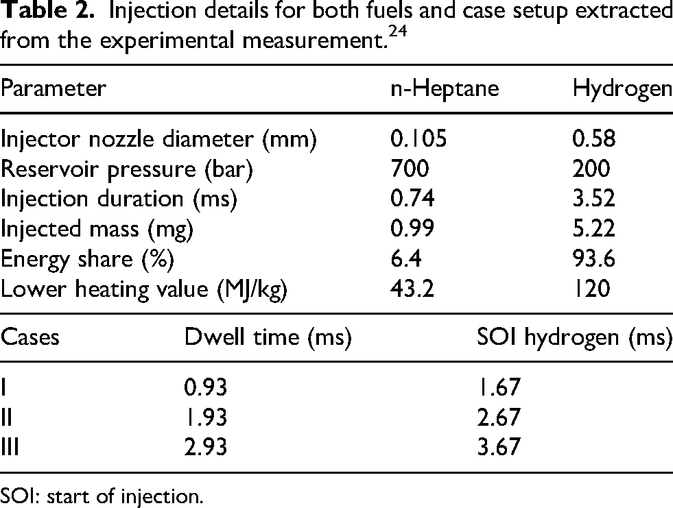
SOI: start of injection.
A total of 0.99 mg of n-heptane and 5.28 mg of hydrogen are injected through individual single hole injectors with a converging layout as shown in Figure 1(a) and hole diameter of 0.105 mm for the n-heptane and 0.58 mm for the hydrogen. Total injected energy is 676.8 J, 6.4% of which is accounted by the n-heptane pilot.
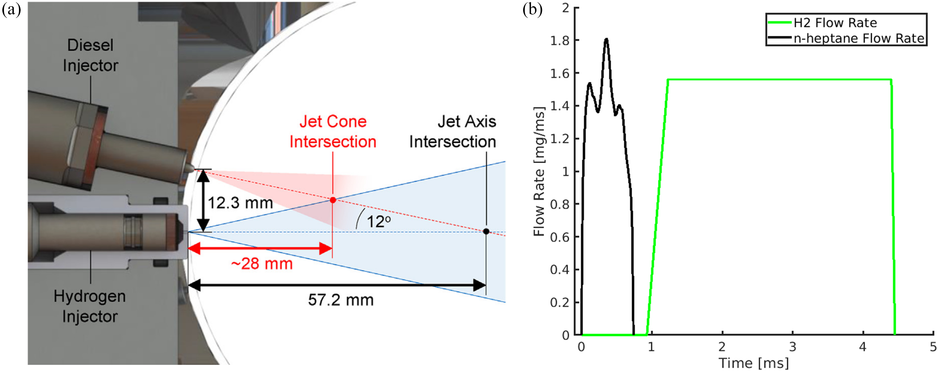
(a) Hydrogen and diesel injector configuration used in the experiments. 24 (b) The flow rate profiles imposed as boundary conditions of the n-heptane and hydrogen injections for Case I.
Numerical setup
The simulations solved the fully compressible Navier–Stokes equations with detailed species and internal energy transport, coupled to spray and combustion sub-models, in the CONVERGE computational fluid dynamics (CFD) 31 software framework. The pressure-implicit with splitting of operators algorithm was selected for pressure–velocity coupling, with a density-based convergence criterion. Second-order spatial accuracy was achieved using a blended Monotone Upstream-centered Scheme for Conservation Laws scheme with total variation diminishing flux limiting, while time integration used a variable time-step constrained by Courant-Friedrichs-Lewy (CFL), chemical source terms, and parcel motion. The maximum velocity-based CFL number was limited to 1, with additional constraints imposed by chemical heat release and parcel dynamics. All governing equations were solved in conservative form with strict conservation enforced for all transported quantities. Turbulence was modeled using LES with a dynamic Smagorinsky-type sub-grid scale model. The SGS kinetic-energy formulation was enabled, together with the Werner–Wengle 32 wall model for near-wall treatment. A time interval of 0–8 ms was simulated. The numerical domain is a cube with a side length of 114 mm, as per the experimental study. The geometry of the hydrogen injector nozzle is also part of the mesh, and it is modeled as a cylindrical pipe having 0.58 mm of diameter and 1 mm of length, centered with respect to one of the walls of the chamber, as by Rorimpandey et al. 24
The n-heptane pilot injection was modeled using Lagrangian particle tracking with KH-RT breakup
33
and dynamic drag. Liquid n-heptane (C
Hydrogen was introduced through a dedicated mass-flow inlet boundary, supplying pure H
The pre-combustion process used in the experiments is not simulated. The domain was initialized as a homogeneous mixture at 5.2 MPa and 890 K, representative of the constant-volume experimental conditions. The initial gas composition corresponded to an oxidized, vitiated mixture containing O
Converge CFD implements a Cartesian grid of a specified base size of 4 mm, locally refined at the injection locations, where the jet have the highest Mach number. These fixed refinements are aligned with the axis of injection of each fuel, so that each jet is orthogonal to the upstream cell face. The cell size of the refined regions is 0.125 mm for the heptane and 0.0625 mm for the hydrogen, and extends for 15 mm along the injection direction. Additionally, automatic mesh refinement (AMR) was dynamically triggered based on sub-grid scale (SGS) criteria on velocity, temperature and species mass fraction, refined down to a minimum cell size of 0.125 mm. This ensured adequate resolution of both the premixed hydrogen regions and the liquid-fuel vaporization zones. Refinement was further enforced near fixed refinement interfaces to avoid resolution discontinuities. The total number of computational cells was capped at 50 million to control computational cost.
Figure 2(a) shows the resulting mesh in the center of the domain before hydrogen ignition. Figure 2(b) shows the growing number of cells throughout the simulation, due AMR. In the picture, a substantial change of slope closely follows the instant of hydrogen SOI in each case.
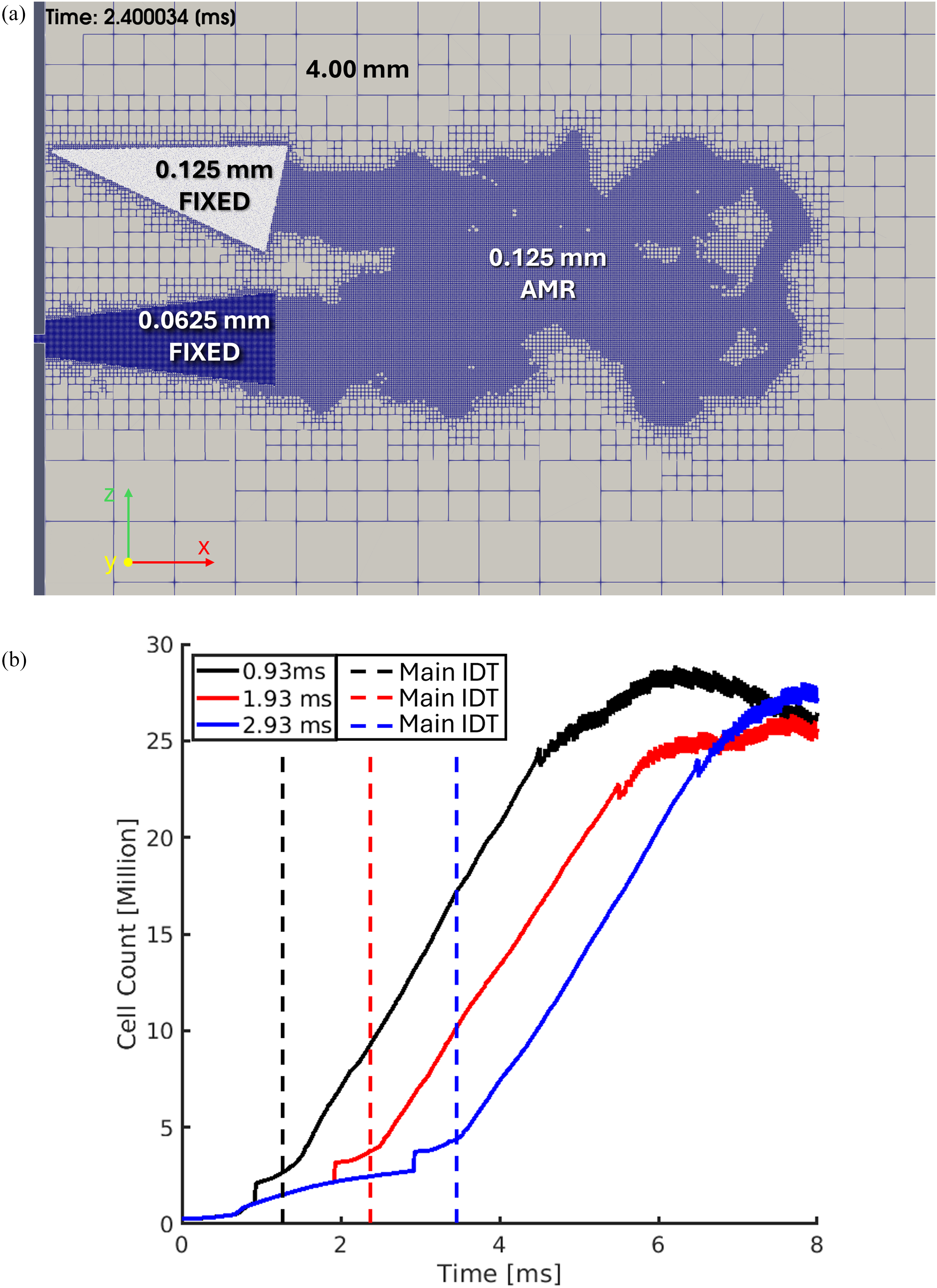
(a) The mesh through the center of the domain before hydrogen ignition. (b) The cell count for all three cases against time.
It is important to note that shock-resolved accuracy is not claimed in the present simulations. This limitation may influence the prediction of near-nozzle jet development and flame lift-off stabilization. However, the current mesh resolution is considered sufficient for capturing the macroscopic mixing and combustion characteristics focused on in this work.
Results and discussion
Validation of LES results
Figure 3(a) compares mid-plane temperature contours from LES with Schlieren images from the experiment for the short-dwell and long-dwell cases. The first row corresponds to the experimentally derived pilot ignition delay, obtained from pressure traces and reported in Table 3. In the simulations, ignition occurs at 0.57 ms in both cases. Between 0.57 and 0.70 ms, the LES indicates further development of the n-heptane flame, reflected by the broader flame structure at the later time.
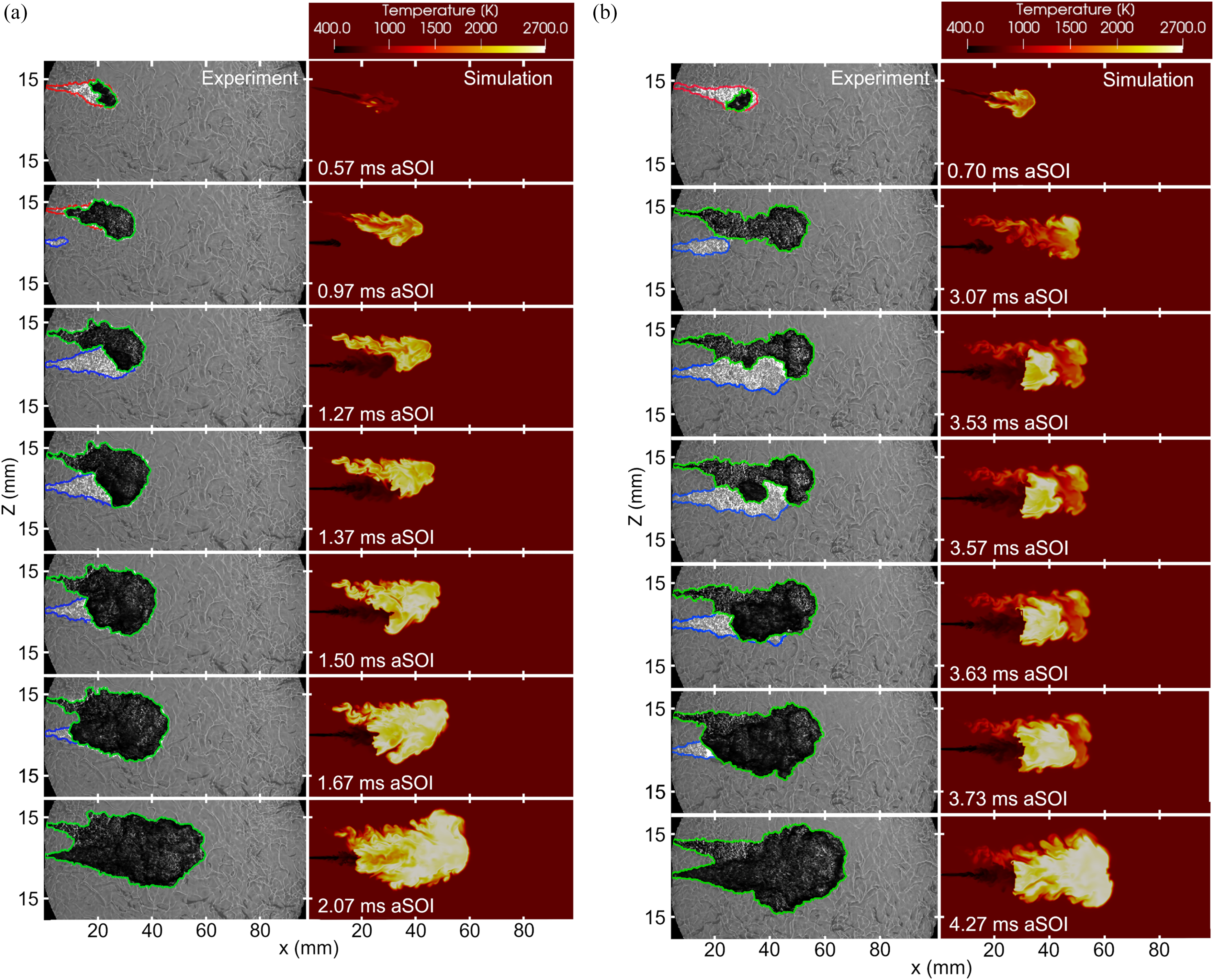
A comparison of the Schlieren imaging from (black and white) the experiments and the simulation 24 (temperature contour) for (a) the dwell time of 0.93 ms (Case I) and (b) the dwell time of 2.93 ms (Case III). In the post-processed Schlieren images, the red, blue, and green contours denote the heptane jet, the hydrogen jet, and the flame, respectively.
Experimental versus simulated IDT (derived from aHRR). 24
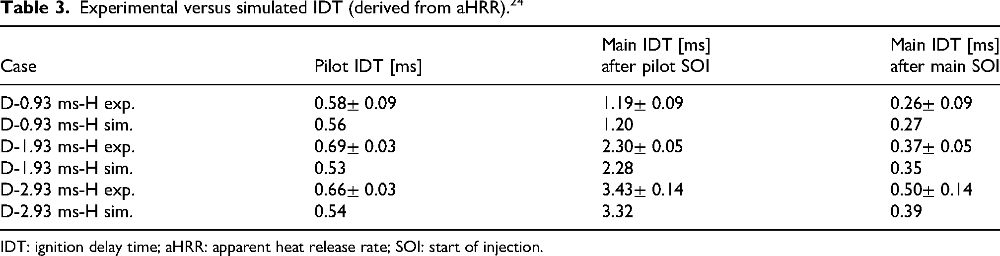
IDT: ignition delay time; aHRR: apparent heat release rate; SOI: start of injection.
The second row shows snapshots acquired 0.4 ms after pilot ignition for the short-dwell case and 2.37 ms after pilot ignition for the long-dwell case. In the long-dwell configuration, the LES predicts a pronounced cooling of the heptane flame, indicating decay of the pilot radical pool before hydrogen ignition. The third and fourth rows illustrate the subsequent kernel development in the main fuel, highlighting the transfer of ignition from the n-heptane radical pool to the hydrogen mixture. The third column of Table 3 reports the main-fuel ignition delay measured after hydrogen SOI, which provides an approximate measure of the degree of hydrogen premixing before ignition. The longer hydrogen ignition delay observed in the long-dwell case is consistent with the reduced reactivity caused by the cooling of the pilot flame. In both experiment and simulation, the main hydrogen flame initially ignites near the jet tip. However, in the long-dwell experimental case, an additional upstream ignition kernel is observed at 3.57 ms, which merges with the tip kernel by 3.63 ms. The last two rows show the flame stabilization behavior. The LES consistently predicts flame lift-off, whereas the experimental flames remain anchored at the nozzle. This discrepancy is likely related to an under-prediction of radial jet spreading and shear-layer mixing in the simulations, leading to elevated axial velocities and scalar dissipation rates near the nozzle. Comparing the two simulated cases, the predicted lift-off distance is smaller in the short-dwell configuration, which may be attributed to the higher temperature of the residual pilot flame, promoting reactions closer to the hydrogen injector.
Overall, the topology of the n-heptane and hydrogen experimental flame, the timing of the interaction between the jets, as well as the progression of the hydrogen flame toward the hydrogen injector nozzle, are well captured by the simulation.
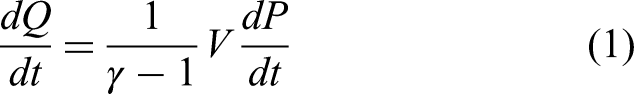
The aHRR for each case is shown in Figure 4. The LES results were compared with multiple realizations of the experimental data. The ignition delay time (IDT) of both fuels reported in the experiments shows variations not only for different dwell time cases but also for runs of the same dwell time. This scattering in aHRR and IDT can result from fluctuations in the turbulent flow and the thermodynamic variables in the combustion chamber, such as random hot spots. All experimental and simulation profiles have undergone the same filtering procedure to eliminate high-frequency fluctuations in the data. The aHRR in both the experiments and simulation is calculated from the pressure trace using the following equation:
40
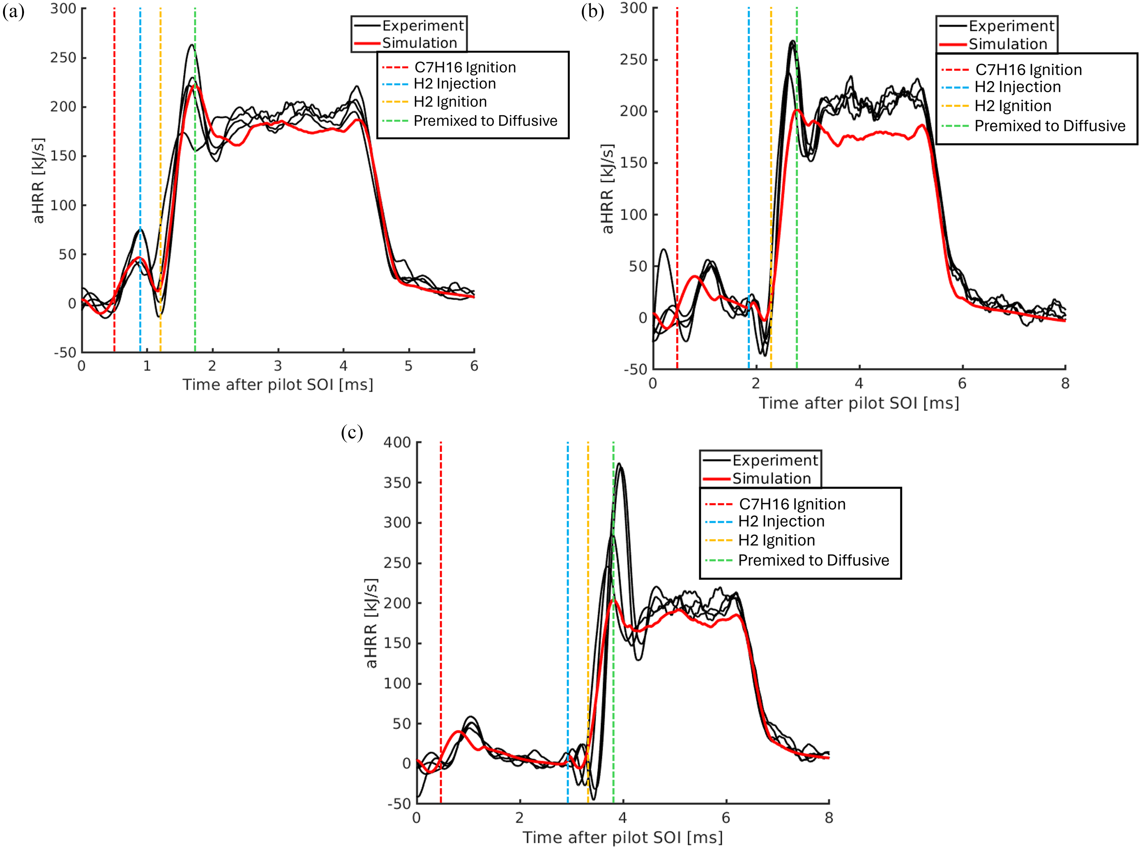
The aHRR from LES and several experimental runs for different dwell times of (a) 0.93 ms (Case I); (b) 1.93 ms (Case II); and (c) 2.93 ms (Case III).
For all cases, the first aHRR peak, around 1 ms, shows the onset of ignition of n-heptane, which occurred shortly after the end of the n-heptane injection. The heat release from hydrogen combustion can be divided into two phases: partially premixed flame propagation upstream toward the jet nozzle and diffusion-controlled combustion. Considering Case I, aHRR starts raising again, after the pilot bump, at 1.20 ms, and reaches its peak at around 1.7 ms, denoting partially premixed combustion along this time span. aHRR then flattens at 2.07 ms, indicating a quasi-steady-state hydrogen jet diffusion flame. In this phase, combustion is controlled by the rate at which fuel and oxidizer are supplied to the reaction zone of the hydrogen jet. The aHRR from the diffusion flame shows good agreement between the experiment and simulation for the short and long dwell time cases. However, in the medium dwell-time case, quasi-steady-state aHRR is under-predicted. The cause of this miss-prediction could be found in slightly different hydrogen mass flow rates between the experiments and simulations. Constant steady-state hydrogen injection profiles are used in the simulations, whereas some variations may be present in the experiments.
Counterflow diffusion flame extinction analysis
To better understand the lift-off discrepancy, it is essential to consider the established mechanisms for flame lift-off in non-premixed jet flames, which include (a) high-scalar dissipation rates near the nozzle, leading to local flame extinction, 41 (b) edge flame propagation speeds being slower than the local flow speeds in the mixing layer, preventing the flame from reaching the nozzle, 42 and (c) the flow residence time being shorter than the ignition delay time of the mixture.43,44
Figure 5(a) shows the hydrogen jet velocity and Mach number radial profiles at 4 ms after pilot SOI, at different distances from the nozzle, for the medium dwell case. The flow is primarily subsonic, except for the jet-core close to the nozzle. At 4 mm and 8 mm from the nozzle, the high velocity gradient in the radial direction increases local scalar dissipation, which implies flame extinction in the near nozzle region. 41 Moreover, jet velocity is very high also at the periphery, before the sharp drop, possibly higher than flame regression speed. 42 Thus, the over-prediction of the lift-off of the hydrogen flame is due to the under-prediction of the hydrogen jet’s radial spreading, which could result from the low mesh resolution in the injector pipe and in the proximity of the nozzle region. Downstream of the jet core region, the flow residence time increases, the velocity drops, and the jet spreads significantly in the radial direction, leading to increased mixing and a low scalar dissipation rate, which enables the flame to sustain itself downstream of the jet core.
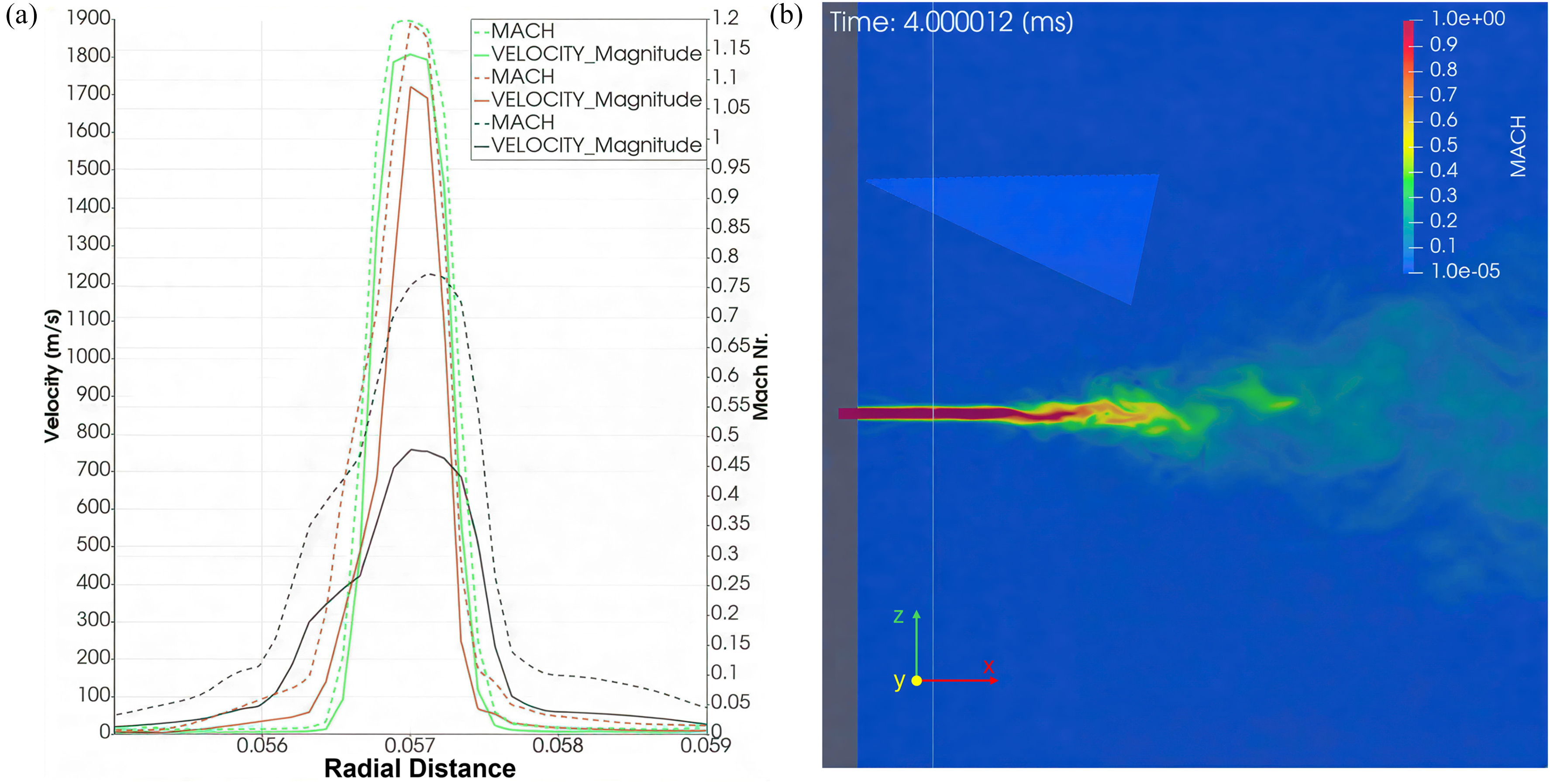
(a) Velocity and Mach number profile along the radial direction of the H
To provide a canonical reference for flame extinction under the thermochemical conditions relevant to the present simulations, a series of laminar opposed-flow (non-premixed) hydrogen–air flames was computed using the
For each strain-rate level, the flame was solved to steady state, and the maximum temperature
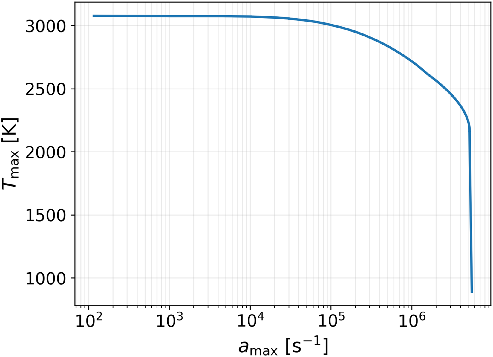
Evolution of
At the extinction point, several commonly used strain-rate definitions were evaluated, including the mean axial strain rate, the maximum axial strain rate, the inlet potential-flow strain rates, and the axial strain rate at the stoichiometric surface. The latter,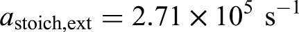
The counter-flow extinction analysis provides a quantitative reference for the maximum strain (or, equivalently, scalar dissipation rate) that a diffusion flame can sustain under the present thermochemical conditions. To establish a quantitative extinction threshold in terms of scalar dissipation rate, the stoichiometric scalar dissipation rate at extinction,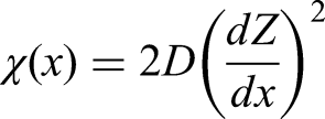
Figure 7 shows an instantaneous snapshot of the near-nozzle region, where contours of the mixture fraction in a narrow band around the stoichiometric value (
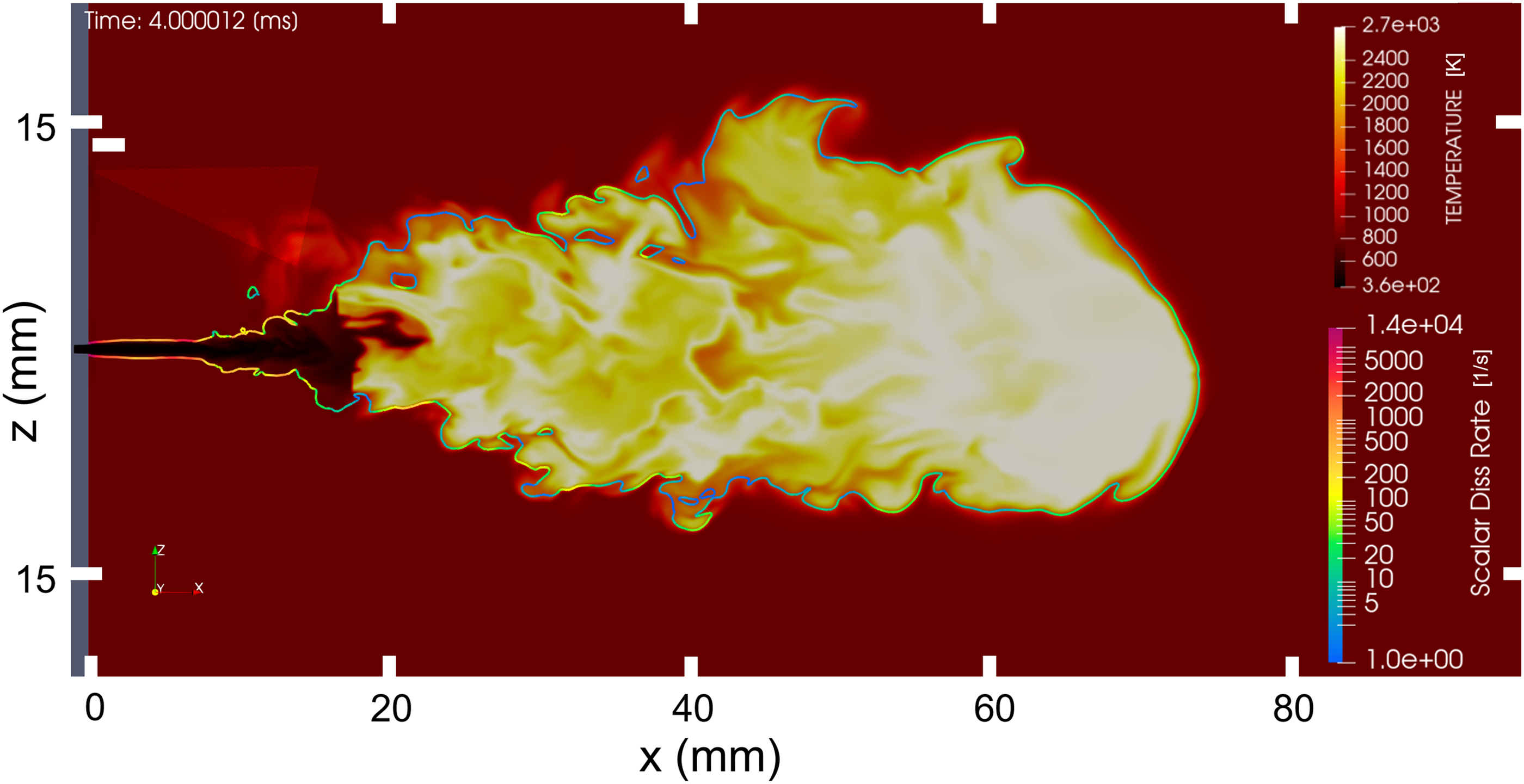
Instantaneous temperature field with the stoichiometric mixture-fraction surface (
The stoichiometric surface forms a thin, highly convoluted layer that follows the jet shear region. In the immediate vicinity of the nozzle exit, this surface is exposed to very large scalar dissipation rates, with values exceeding the extinction threshold
Beyond mixing and scalar-dissipation effects, unsteady flame–flow interaction mechanisms (e.g. TFUP-type stabilization regimes 48 ) may also influence flame reattachment behavior in hydrogen flames, but their assessment requires dedicated diagnostics and is left for future work.
Overall combustion process
Figure 8 shows instantaneous mid-plane snapshots at four representative times (
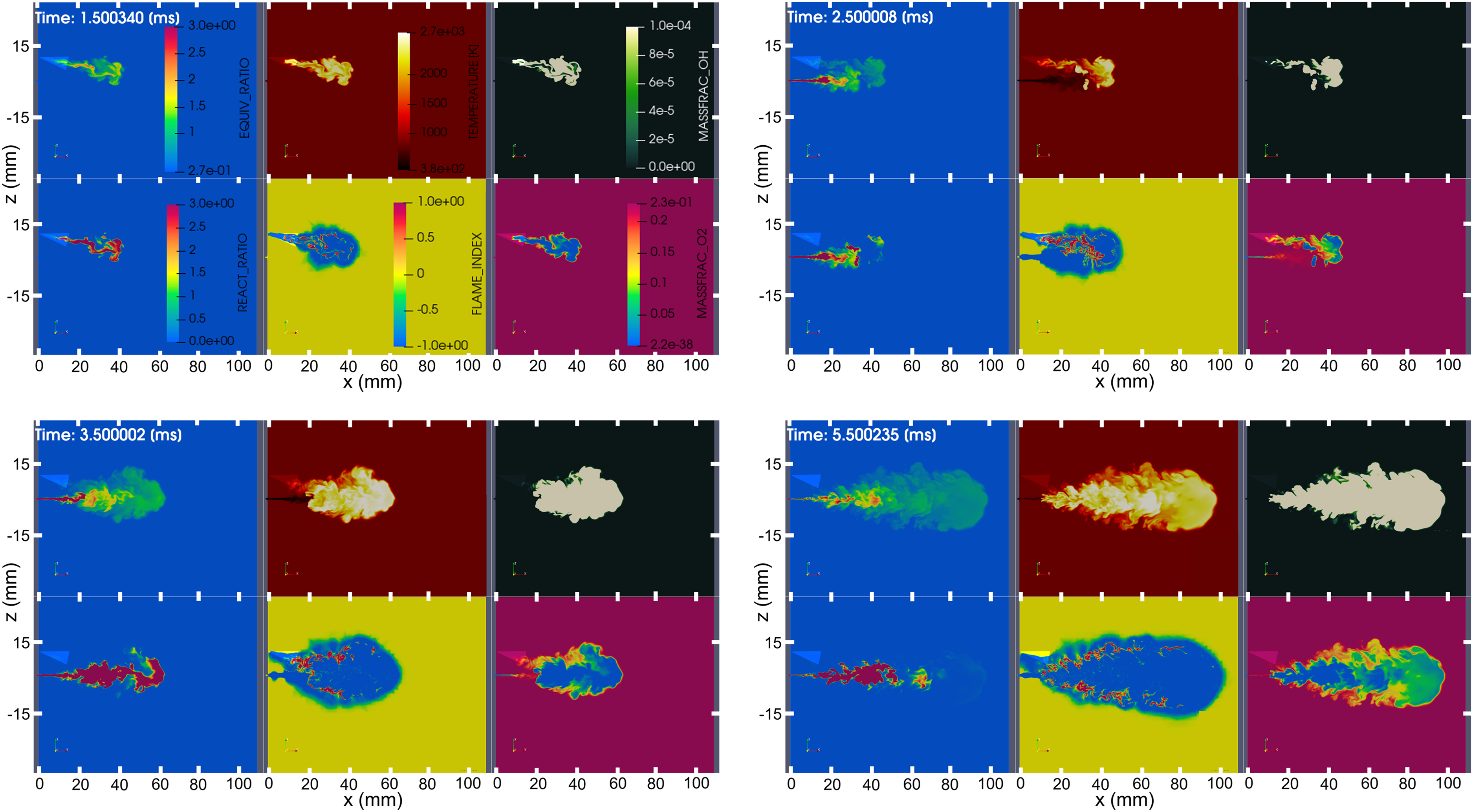
Instantaneous mid-plane snapshots at
The equivalence ratio reported is an element-based quantity and it can be written as follows: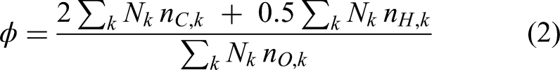
The quantity
The flame topology is assessed using a Takeno-type flame index.
49
The (normalized) flame index is based on the alignment of fuel and oxidizer gradients,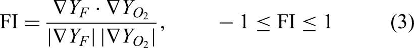
Time
At
Impact of dwell time on hydrogen combustion
The temperature contour in Figure 9 shows the combustion behavior of the n-heptane flame. As can be seen, the ignition begins at the tip of the n-heptane spray. Similar to the earlier discussion on the hydrogen jet, this is due to the long residence time, low scalar dissipation rate, and low flow speed in the n-heptane spray tip, all of which favor ignition and flame stabilization. The flame quickly spreads upstream towards the injector due to the edge flame propagation mechanism.42,44
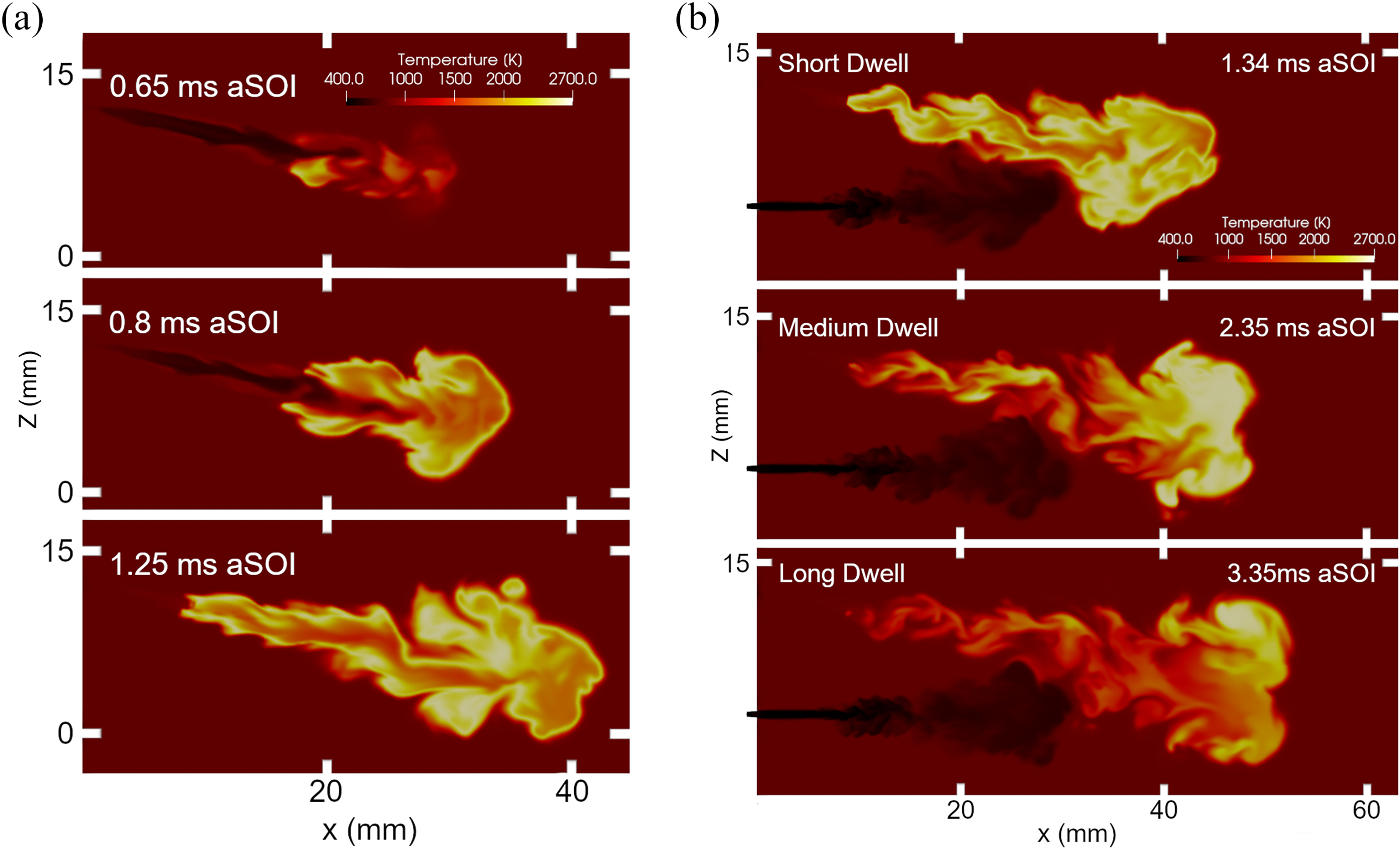
Temperature distribution along the center of the domain illustrates the (a) stages of n-heptane combustion for the short dwell time case (Case I) and (b) immediately before hydrogen ignition for the three dwell time cases.
By increasing dwell time, the pilot combustion has more time to evolve, so the state of the ignition source changes, and the effective penetration length of the pilot flame extends further into the chamber. As a result, the location where the hydrogen jet first interacts with the pilot can shift, in addition to the flame being progressively cooled by entrainment. This further clarifies why hydrogen IDT increases as dwell time increases. Figure 10 shows the joint distribution of equivalence ratio and temperature in the combustion chamber, commonly referred to as a
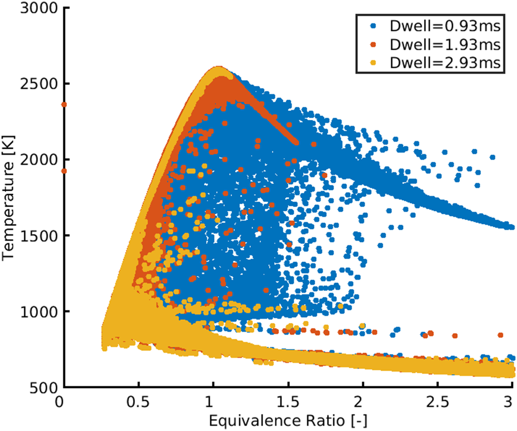
Since hydrogen SOI occurs after n-heptane ignition, the n-heptane flame is not affected by the hydrogen injection until the hydrogen jet reaches the n-heptane flame. As explained above, Figure 9(b) shows that as the dwell time increases, the n-heptane flame cools down by the ambient gas. When the hydrogen jet flow reaches the n-heptane flame, the hydrogen/air mixture ignition becomes slower with increasing dwell time. The slower ignition allows more hydrogen mixing with the hot gas in the n-heptane flame, and as such, once ignited, the peak heat release rate is higher in the long dwell time case (e.g. Case III; Figure 4).
Figure 11 shows again a
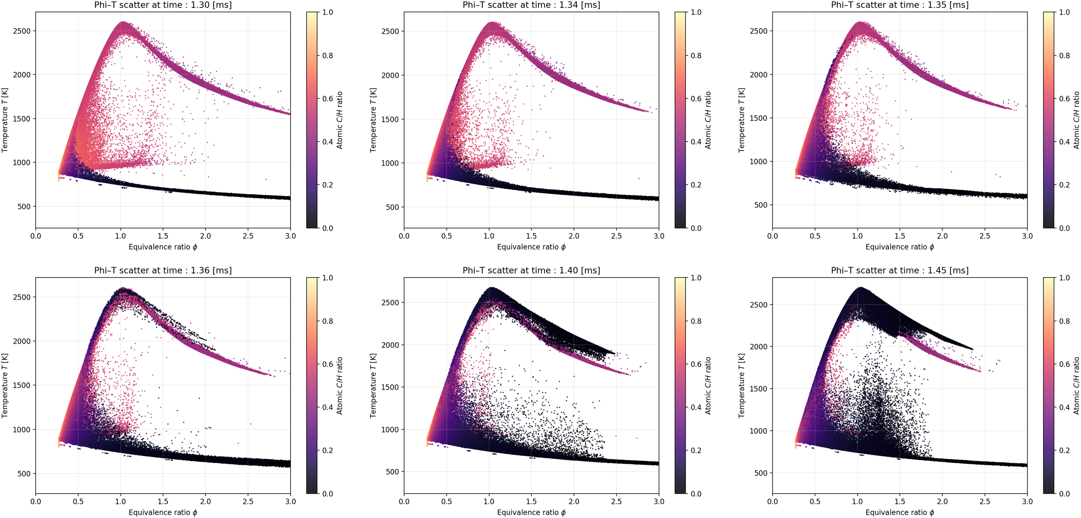
The points are colored by the local atomic carbon-to-hydrogen ratio (C/H), computed from the major resolved species mass fractions as the ratio of total carbon atoms to total hydrogen atoms present in the mixture. In this representation, pure hydrogen, pure n-heptane and the preheated ambient gas are represented, respectively, from values of C/H =0, C/H
Since both the C/H and the equivalence ratio are atom-based, both scalars are conserved throughout reactions. Therefore, the increase in C/H above 0.44 and the shift towards the left part of the diagram, observed in the combustion products of n-heptane, is caused exclusively by mixing with the ambient gas.
At
The production rate of NO
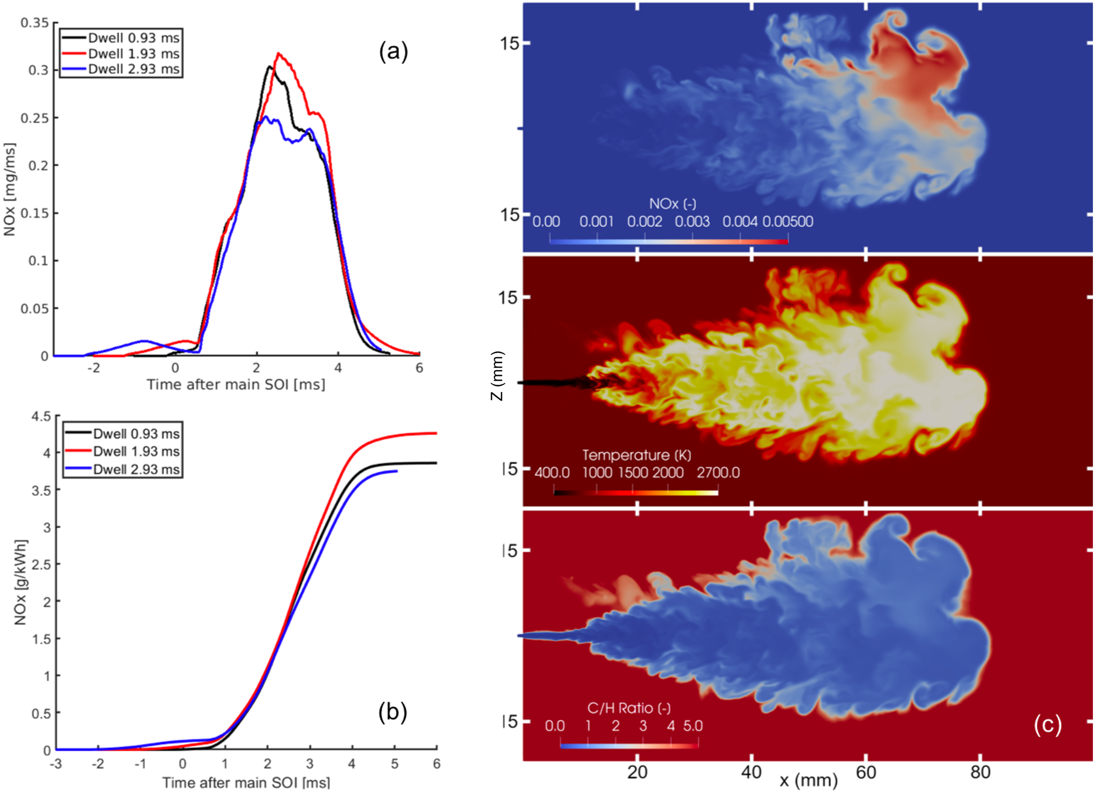
(a) Temporal evolution of the rate of NO
The NO
Conclusions
LESs of hydrogen/n-heptane dual-fuel combustion in a constant-volume vessel were performed to investigate jet–jet interaction, ignition behavior, and NO
In all cases, hydrogen ignition occurs once the hydrogen jet intersects the n-heptane pilot flame. Short dwell times lead to nearly immediate hydrogen ignition upon intersection, whereas longer dwell times result in delayed ignition due to cooling and dilution of the pilot flame before interaction. These trends are consistently observed in both LES and experiments. The highest NO The onset of n-heptane ignition is at the spray tip due to the long residence time and low scalar dissipation rate in the region. The onset of hydrogen ignition is at the jet tip by the n-heptane flames. The flames in both the n-heptane jet and the hydrogen jet propagate upstream toward the nozzle. LES predicted a short lift-off length for the hydrogen flame, but longer than that observed in the Schlieren images. Combustion analysis confirmed that the discrepancy in flame lift-off results from an over-prediction of the local scalar dissipation rate and the under-prediction of the jet spreading in the radial direction.
Footnotes
Acknowledgements
This work is sponsored by the Swedish Energy Agency and Scania CV AB within the HYZERO project. The simulations were performed on resources provided by the National Academic Infrastructure for Supercomputing in Sweden (NAISS). The authors thank Convergent Science for providing the CONVERGE licenses and technical support for this work.
Funding
The authors disclosed receipt of the following financial support for the research, authorship, and/or publication of this article: The authors received funding from the Swedish Energy Agency.
Declaration of conflicting interests
The authors declare no potential conflicts of interest with respect to research, authorship, and publication of this article.
Data availability statement
Data will be made available on request.