
Abstract
This work presents an experimental investigation of the acoustic properties of a slit in the presence of a bias flow under moderate- and high-acoustic excitations. Impedance tube experiments are discussed for a geometry inspired by deep punching resulting in a cut in the plate. The acoustic transfer impedance of the plate is discussed for several bias flow velocities, acoustic excitation, and different frequencies. In the range considered for this study, a bias flow appears to have two main effects, globally enhancing the sound absorption of the plate and creating a protective layer downstream of the plate due to the interaction between the slits. A maximum of the enhancement factor is found at a specific ratio between the acoustic velocity and the bias flow velocity. Two simple asymptotic behaviors are found, dominated by the flow or by the acoustic excitation, respectively. The behavior of the inertance is complex. Globally the inertance decreases with decreasing flow Strouhal number while its dependency on the amplitude of the acoustic velocity is less obvious.
Introduction
In combustion chambers of gas turbines, multi-perforated liners are used to provide film cooling of the walls and offer an excellent candidate to disrupt thermoacoustic instabilities in emerging technologies, such as hydrogen combustion. A perforated plate offers an excellent sound absorption ability and provides means to manipulate and re-distribute the acoustic energy loss at the chamber’s walls, making the system stable.1–5 In these conditions, the plate encounters high-acoustic excitation and displays a non-linear response. Several works suggest that the presence of non-linear effects can deteriorate the performance of the absorbers.6–9 However, the presence of a bias flow through the orifices impacts the absorption characteristics of the liner. Extensive research has been performed on the so-called bias flow liners and a recent review of such publications is presented by Lahiri and Bake. 10 In the literature, most of the works focus on circular perforations in the presence of a mean flow.11–15 Salikuddin et al. 11 find that the effect of acoustic excitation amplitude is similar to that of a bias flow. Jing and Sun 13 compare a discrete vortex model and a quasi-steady method to study high-intensity sound absorption at an orifice with a bias flow. Eldredge and Dowling 16 prove the effectiveness of a perforated liner system with a mean bias flow in the absorption of planar acoustic waves in a circular duct. The combination of a bias flow and high-acoustic amplitudes is also studied by Luong et al. 17 to extend the linear theory of Howe18,19 to predict the attenuation of sound by vorticity production in a bias flow aperture. Furthermore, several works focus on experimental results for the interaction between an acoustic field with a bias flow.15,20–23 Fabre et al.24,25 focus on the impact of flow through a thin circular aperture. Zhou and Bodèn14,16 find that a bias flow makes the acoustic properties more complex compared to the no bias flow case, especially when the velocity ratio between acoustic velocity and mean flow velocity is close to unity. In recent works, Guzmàn-Iñigo et al., 26 Hirschberg et al. 27 and Burgmayer et al.15,28 discuss the effect of the geometry of the perforations on the acoustic response in the presence of flow. Interesting results are obtained with so-called zero mass flow liners where a single-degree-of-freedom liner is attached to an acoustic actuator emitting a secondary high-amplitude sound field, inducing a periodic bias flow in the orifices.29–32
In this work, we focus on a specific slit geometry, introduced in Aulitto et al. 33 obtained by deep punching resulting in a cut in a metallic plate, displayed in Figure 1. This geometry could present a cheaper alternative to slanted perforations, keeping equivalent characteristics. The acoustic behavior of such perforations in the presence of a bias flow in the linear regime is discussed in Aulitto et al., 34 while Aulitto et al. 35 focus on the impact of non-linear effects on the acoustic impedance of the plate.
Schematic representation of the geometry with coalescence of the micro-jets used for film cooling.
Due to the particular manufacturing process, cavities are formed in the plate upstream and downstream of each slit, and in the presence of a bias flow, the individual jets tend to attach to the wall of the cavity downstream of each slit, coalescing and creating the same effect of film cooling as grazing effusion holes. Figure 1 shows that downstream of the plate, the jets are coalescing and the combination of multiple slits creates the same effect of film cooling as grazing effusion holes.
We focus on the effect of a bias flow on the acoustic transfer impedance of the plate and its absorption properties in presence of medium- and high-acoustic excitations when the plate exhibits a non-linear response. However, we restrict our analysis to conditions of moderately high-acoustic excitation amplitudes, for which the response is dominated by a single frequency so that the concept of impedance remains meaningful. The acoustic transfer impedance of the micro-slit plate is experimentally studied, using impedance tube measurements. Special attention is given to the search for relevant dimensionless parameters and asymptotic behavior for low or high values of these parameters. The first section of the results discusses the enhancing effect of a bias flow on the resistance of the plate. Following, a study of the change of resistance due to non-linearities is provided. Further, the study focuses on the behavior of inertance. Finally, the conclusions are summarized.
Experimental setup
Geometry of the samples
In Figure 2, a sketch of the plate geometry is shown together with a picture of the sample, with the relevant parameters summarized in Table 1.
Sketches of the plate and the cross-section of a single slit with the definition of parameters and picture of the sample.
Relevant parameters in Figure 2.
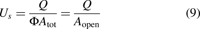
The porosity (of the portion of the plate in the impedance tube) is defined as the ratio between the total open area
Schematic representation of the impedance tube setup.
The microphone closest to the sample (at position
Definitions
The concept of acoustic transfer impedance is introduced in the frequency domain of frequency 
In Aulitto et al.
35
, it is shown that in the same range of frequencies and amplitudes as in the present study, one finds at least an order of magnitude difference in amplitude between the fundamental frequency and higher harmonics. The study is limited to moderately high amplitudes, and in the present work, the concept of impedance is extended in the presence of a bias flow. The study is limited to frequencies
In this open pipe radiation impedance measurement, the sample is replaced by a ring in the sample holder so that the geometry (pipe length and position in the room) is the same as when measuring with a sample. The dimensionless radiation impedance is obtained as

The dimensionless numbers used in this work are presented here.
The Shear number is the ratio between the slit width 
The acoustical Strouhal number (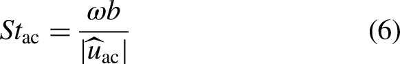
The behavior of the plate can be studied as a function of the Strouhal number of the flow 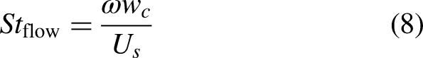
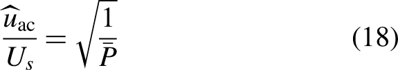
At low frequencies, using Bernoulli’s frictionless quasi-steady-flow equation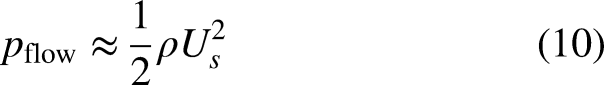

The Reynolds number based on the slit width 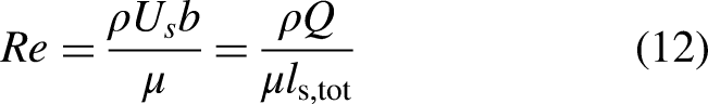
An acoustic Reynolds number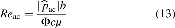
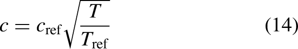
The dimensionless number 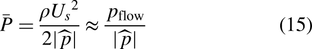
Enhancement of the resistance
Maa
36
suggested that maximum absorption for a micro-slit plate can be obtained when
In Figure 4, the real part of the impedance is shown normalized with the characteristic impedance of air for several flow speeds (Reynolds numbers) as a function of the ratio between the amplitude of the acoustic velocity and the flow velocity. The relevant parameter is the mean flow Reynolds number
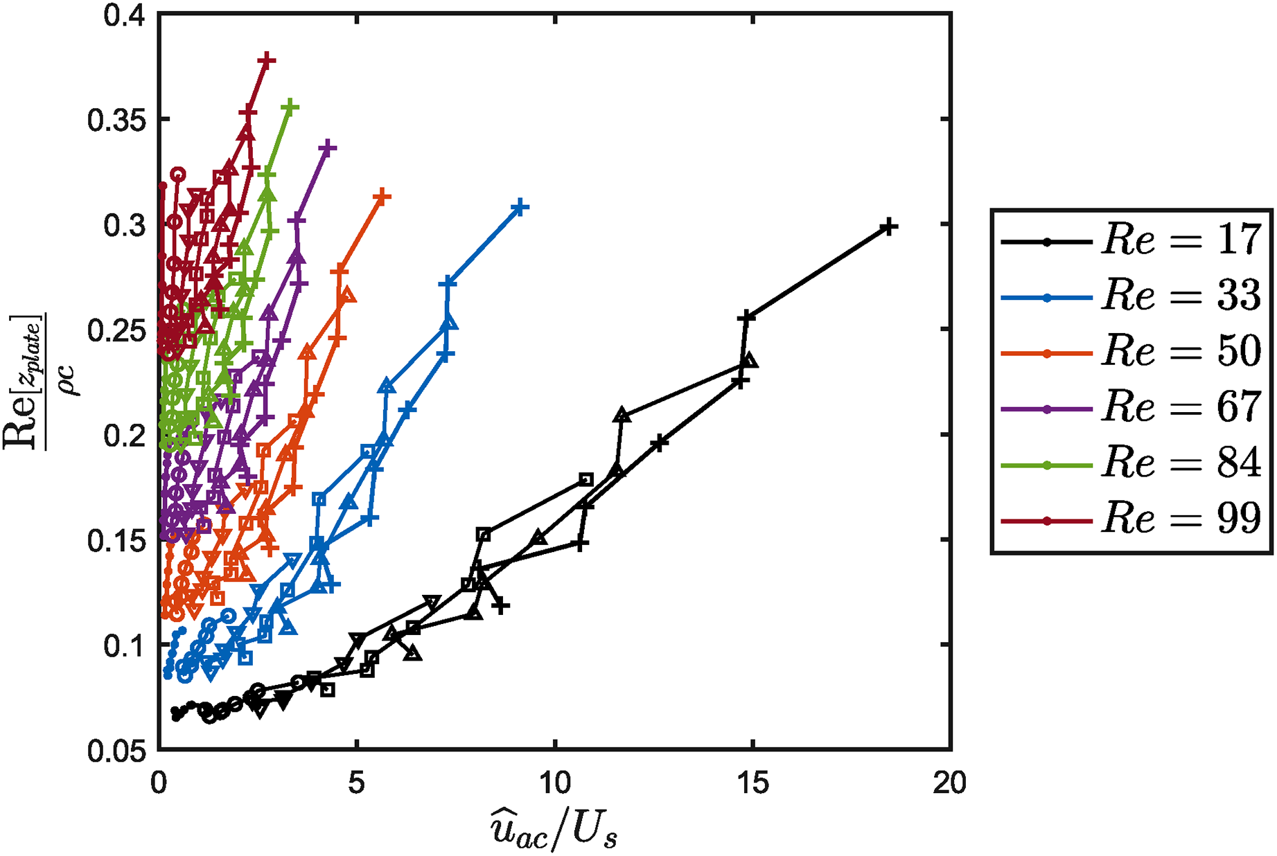
Real part of the acoustic transfer impedance of the plate normalized with the characteristic impedance as a function of the velocity ratio
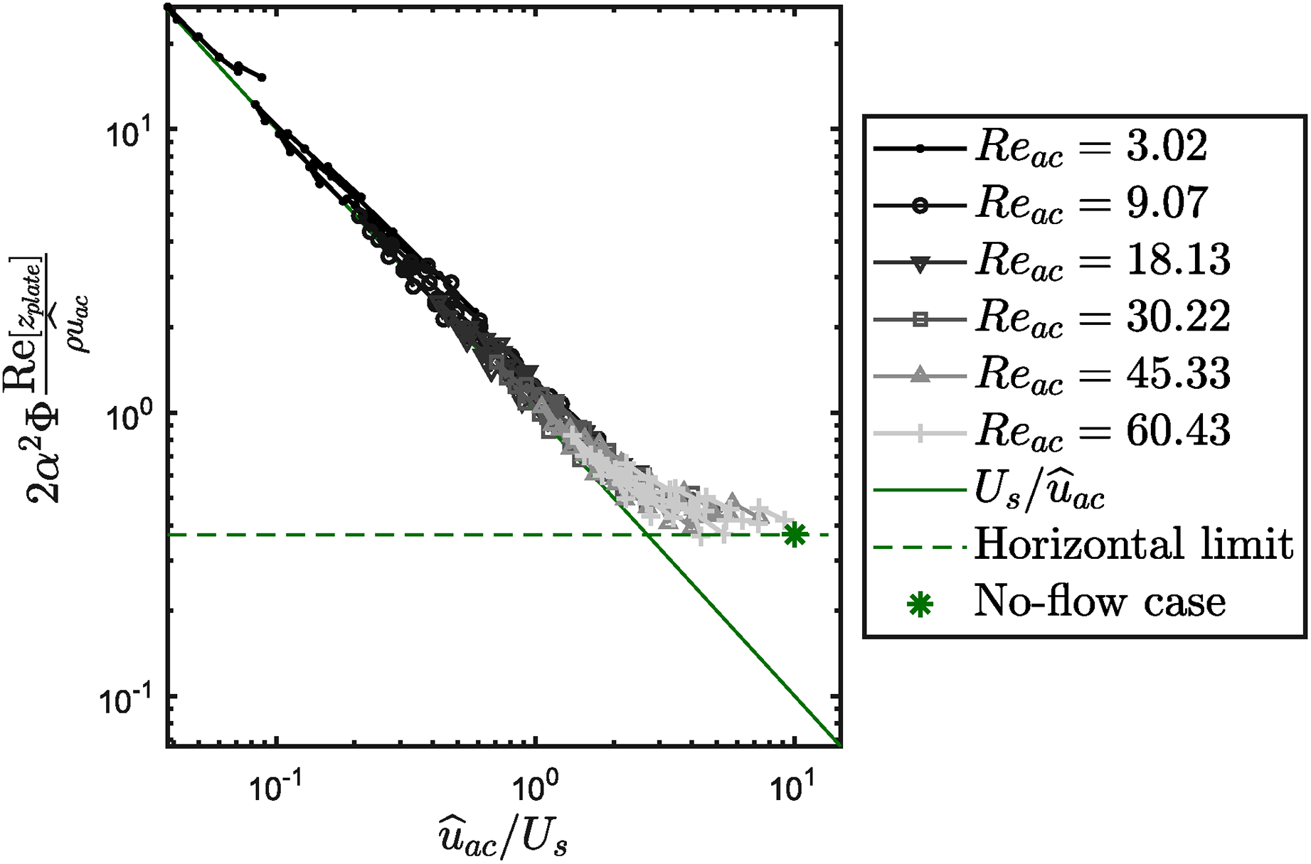
Real part of the acoustic transfer impedance of the plate normalized with the quasi-steady limit for high-acoustic excitations as a function of the velocity ratio
It can be seen that for
A third dimensionless representation for the real part of the acoustic transfer impedance is used in Figure 6. The linear quasi-steady limit
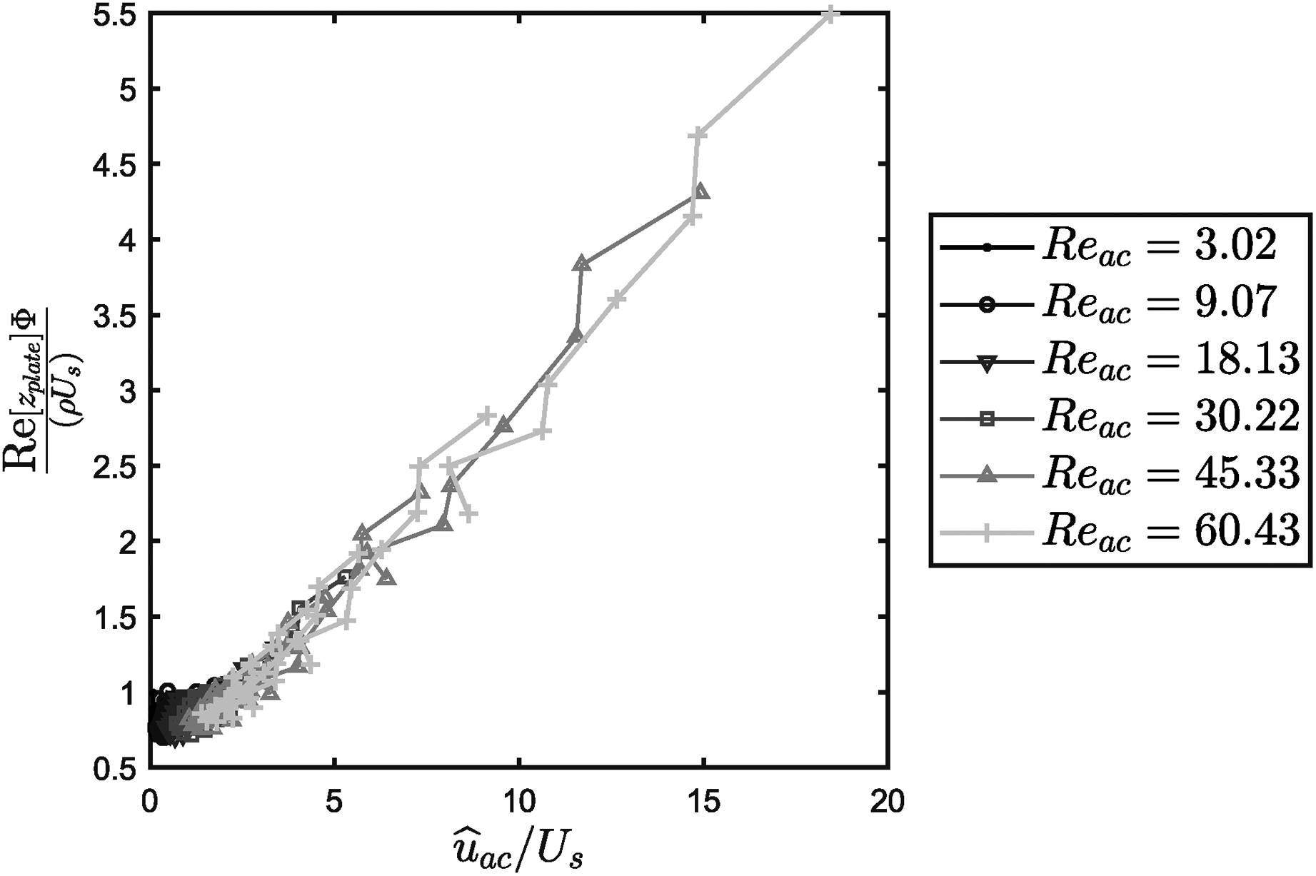
Real part of the acoustic transfer impedance of the plate normalized with linear quasi-steady limit as a function of the ratio
At a given acoustic excitation amplitude (defined in decibels, 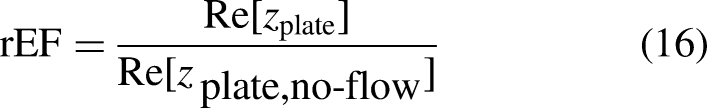
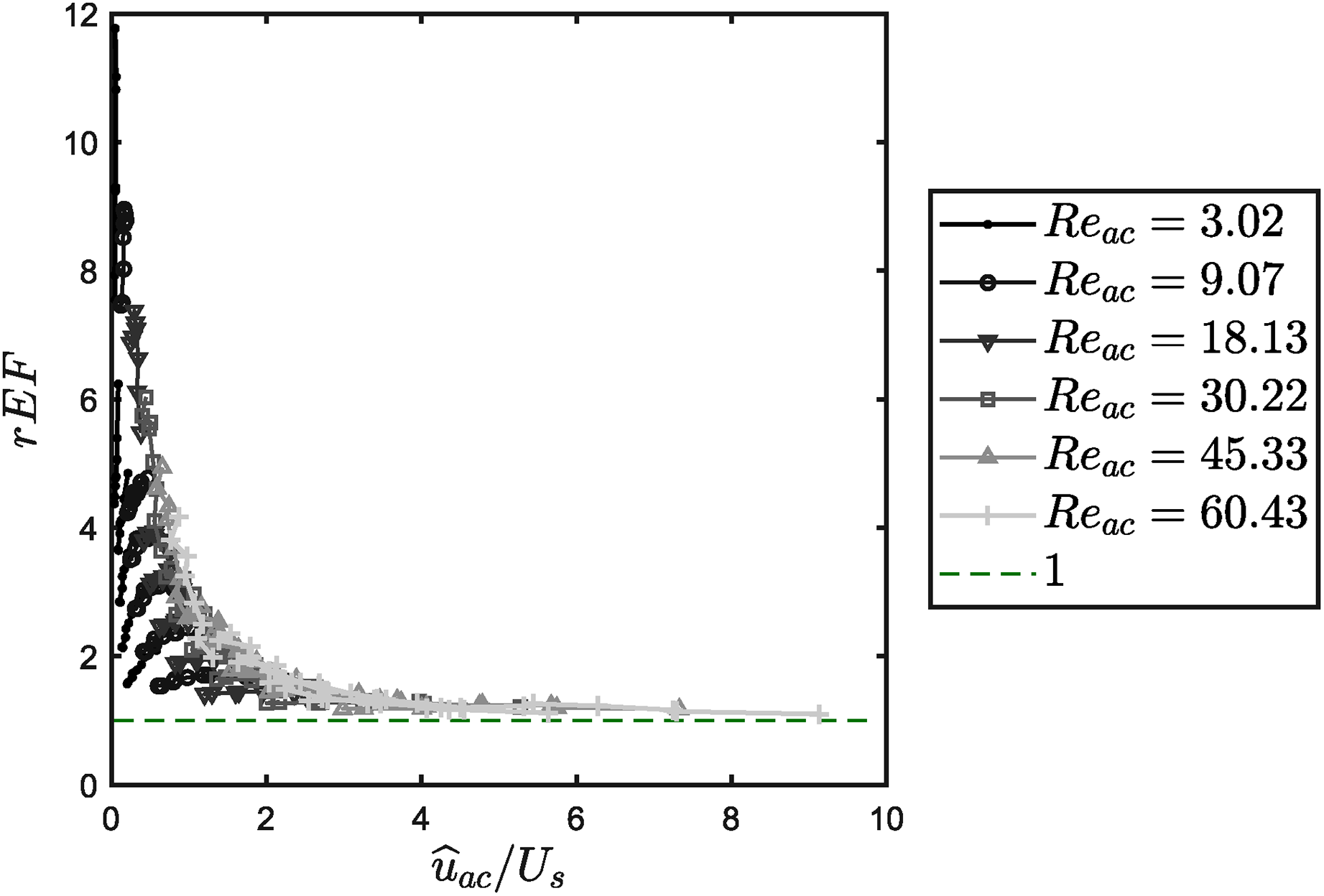
Enhancement factor as a function of the ratio
One sees that, overall, the presence of a bias flow increases the resistance with respect to the no-flow case. Hence, the EF is larger than one.
For low-velocity ratios
(a) A zoom of the enhancement factor for velocity ratio
The maximum EF is shown in Figure 8(b) as a function of the acoustic excitation amplitude in decibels. This shows that the maximum enhancement decreases with increasing acoustic excitation amplitudes. A linear fit of the experimental results with
Change of resistance due to non-linearities
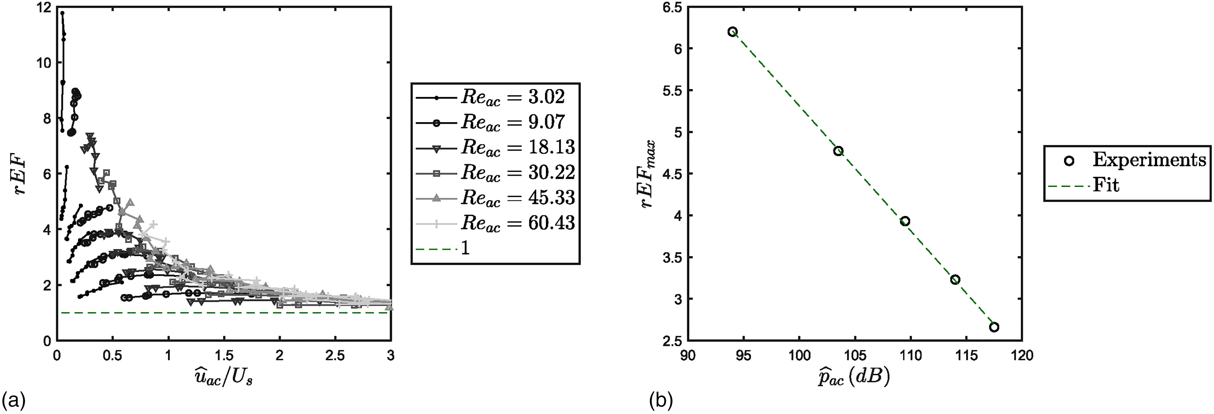
In this section, the change of resistance due to the presence of non-linearities at moderate- and high-acoustic amplitudes is discussed. In the linear case, for the full range of frequencies, the resistance is constant. In absence of main flow, viscous effects are dominated by dissipation in the laminar Stokes boundary layer. In the absence of main flow, at high-acoustic amplitudes, the response of the plate is dominated by formation of vortices due to flow separation that dissipates kinetic energy by turbulence. In the presence of the main flow, the behavior is more complex, with potential movements of the flow separation point. Globally, the effect of viscosity is the same as in the linear case, leading to dissipation in the Stokes layer, flow separation, and dissipation by turbulence. Figure 9 shows the change of resistance
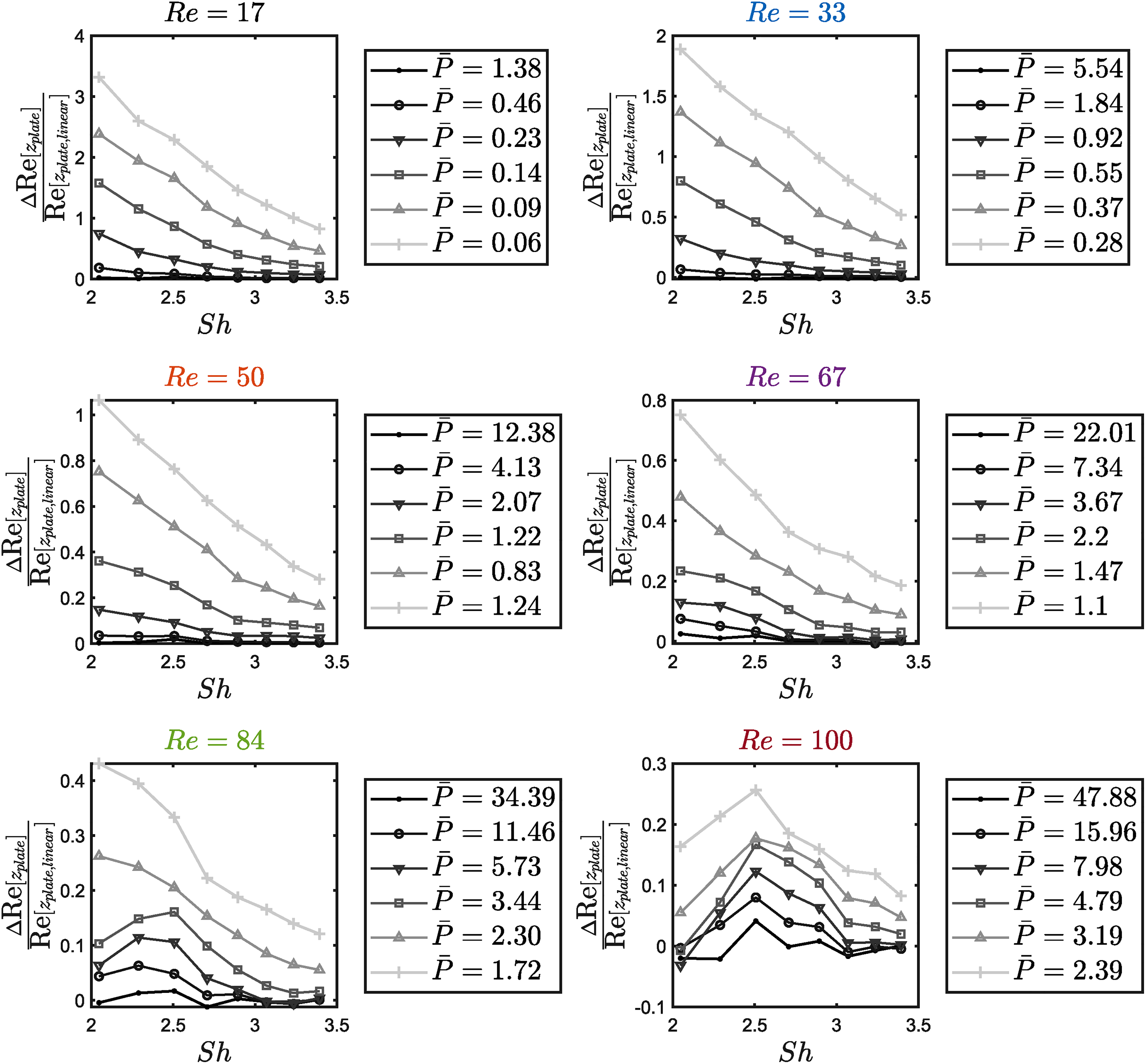
Change of the real part of the acoustic transfer impedance of the plate normalized with the linear case as a function of the Shear number
The linear contribution
Each of the figures corresponds to a fixed flow speed (Reynolds number). Each curve corresponds to a different value of the parameter
Increasing the flow speed, the effect of the non-linearities decreases and for
For low values of
In Figure 10, the change of resistance is shown as a function of the velocity ratio
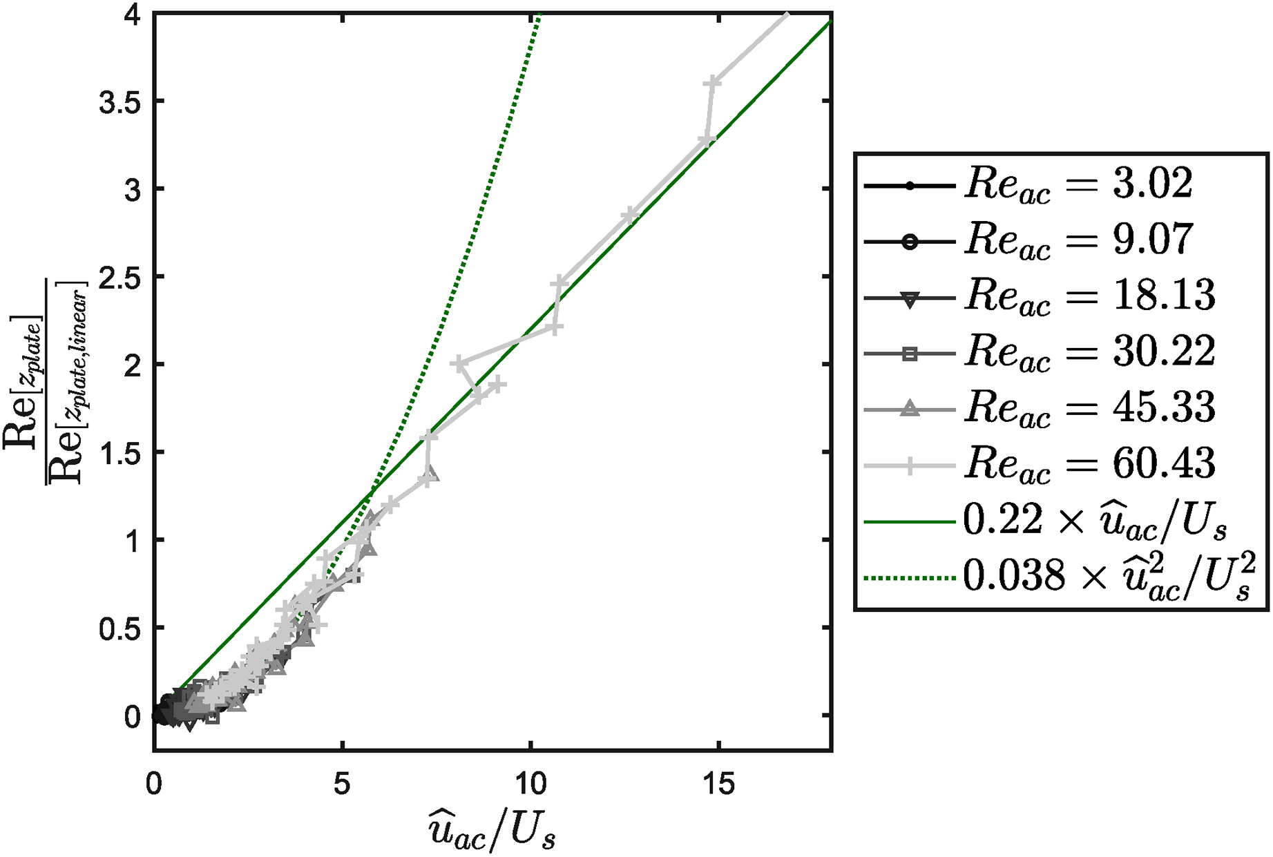
Change of the real part of the acoustic transfer impedance of the plate normalized with the linear case as a function of the velocity ratio
The change in resistance is seen to be proportional to the ratio
Considering the parameter 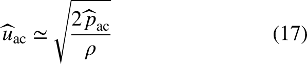
In Figure 11, the change of resistance due to non-linear effects is shown for similar
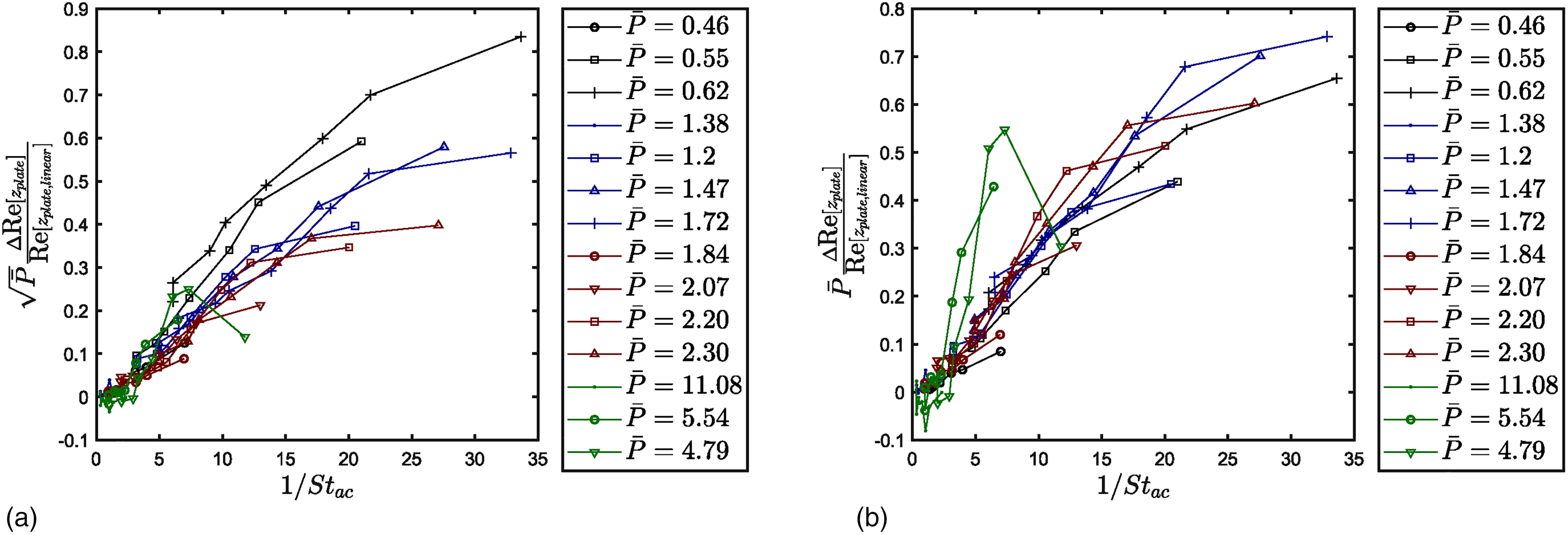
Change of the real part of the acoustic transfer impedance of the plate normalized with the linear case as a function of the inverse of the acoustic Strouhal number (
For each Reynolds number considered in Figure 9, the lines corresponding to
One sees a good collapse of the results for both representations with the dimensionless change of resistance approaching order unity for increasing acoustic Strouhal numbers. Although, a better global collapse is observed for a change in resistance scaled with
Change of inertance due to non-linearities
In this section, the behavior of the imaginary part of the acoustic transfer impedance (inertance) is discussed. The inertance is responsible for a shift in the frequency of the peak of absorption. In Figure 12, the change of inertance due to the presence of a bias flow is shown as a function of the velocity ratio. One sees that, for low and moderate acoustic amplitudes, the inertance is lower in the presence of flow, whereas for high amplitudes, it is slightly higher. A deep in the inertance can be seen around the same
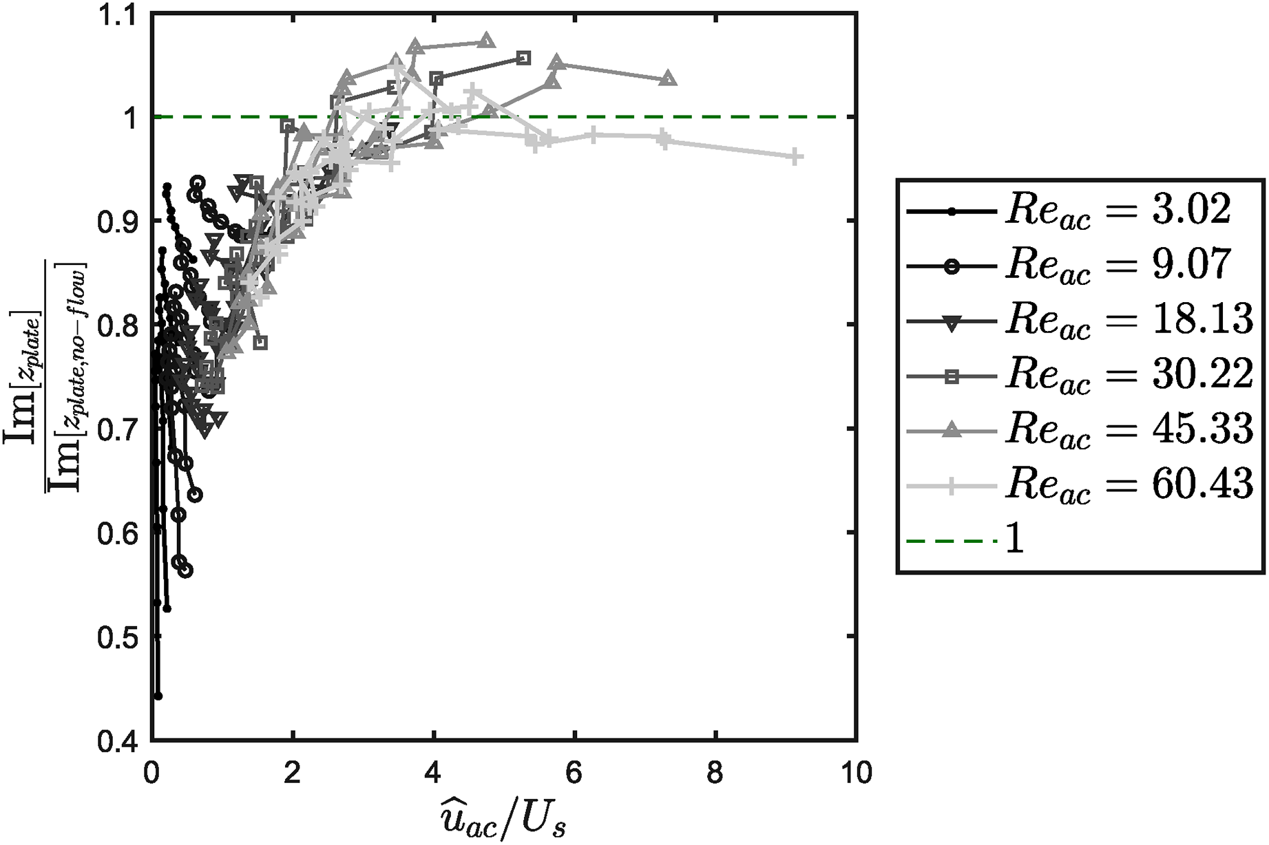
Imaginary part of the acoustic transfer impedance of the plate normalized with the no-flow case as a function of
In Figure 13, the change of inertance with respect to the linear case is shown as a function of the inverse of the flow Strouhal number. One observes a fair collapse of the results for
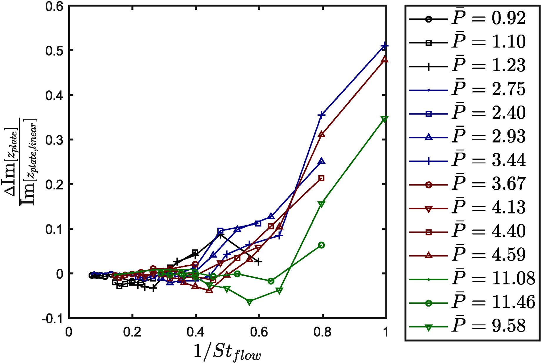
Change of the imaginary part of the acoustic transfer impedance of the plate normalized with the linear case as a function of the inverse of the flow Strouhal number (
Conclusions
Experimental results for the non-linear acoustic transfer impedance in the presence of a bias flow are discussed. Maa
36
suggested that optimal absorption can be obtained with a micro-slit plate backed by a cavity when the resistance of the plate matches the characteristic impedance of air. Introducing a bias flow produces a significant change in the resistance of the plate, which can potentially enhance the absorption properties of the plate. The presence of the flow shows a double effect. On the one side, it increases the resistance, increasing the bandwidth of absorption. On the other side, the inertance decreases, shifting the peak of absorption toward higher frequencies. For low acoustic excitations, the behavior is dominated by the flow, and a simple linear quasi-steady model
Footnotes
Acknowledgements
The authors wish to thank H. Faghanpourganji for their support with the measurement setup for the discharge coefficient. We acknowledge the precious help of L. Hirschberg during the final stages of our measurements. This work is part of the Marie Skłodowska-Curie Initial Training Network Pollution Know-How and Abatement (POLKA). We gratefully acknowledge the financial support from the European Commission under call H2020-MSCA-ITN-2018 (project number: 813367).
Declaration of Conflicting Interests
The author(s) declared no potential conflicts of interest with respect to the research, authorship, and/or publication of this article.
Funding
The author(s) received no financial support for the research, authorship, and/or publication of this article.