
Abstract
The excitation mechanism of a thermoacoustic instability in a 42-element research rocket thrust chamber with representative operating conditions with respect to European cryogenic rocket engines is investigated in detail. From previous research it was known that the chamber 1T mode can be excited by persistent heat release rate oscillations which are modulated by the resonant modes of the liquid oxygen injectors. The excitation source of the longitudinal injector eigenmodes is investigated in this study. Fibre-optical probes measuring the OH* dynamics from the recess volume of two injectors showed additional frequency content which could neither be explained by the chamber acoustics, nor the acoustics of the injection system. Instead, the temporal evolution of these frequencies correlate with the oxidizer flow velocity. In this work we show that the additional flame modulation originates from a hydrodynamic effect in the injection system. Even though the exact process cannot be precisely identified, an effect designated orifice whistling at the injector inlet orifice seems to be a likely candidate. Combining the new results with previous publications about this combustor, it is now possible to explain past and present observations in terms of the hydrodynamic and thermoacoustic conditions which are necessary for the combustion instability to appear. The conditions, which lead to an injection-driven excitation of the 1T mode are matching frequencies of the 2L mode of the injectors and the chamber 1T mode as well as a Strouhal number between 0.2 and 0.4 based on the length and flow velocity of the injector inlet orifice.
Keywords
Introduction
High-frequency combustion instabilities represent a serious risk during the development and operation of liquid propellant rocket engines. 1 These oscillations are generated by the interaction of unsteady heat release and the combustion chamber acoustics. Based on the extremely high power density of rocket combustion chambers, this can cause fast growing pressure oscillations, which may result in damage of the engine. 2
According to Rayleigh 3 energy is transferred into the pressure field if the heat release rate oscillation is in phase with pressure. The actual underlying coupling mechanisms are usually divided into intrinsic and injection coupled mechanisms. 4 Intrinsic coupling describes mechanisms caused by variation of subprocesses inside the chamber as mixing and combustion, whereas with injection coupling, pressure or mass flow variations in the injectors interact with chamber pressure oscillations and amplify them through a modulation of the combustion dynamics. As stated by Hutt and Rocker 4 instabilities due to injection coupling are never completely independent of the intrinsic processes, because they define if the heat release oscillations driven by the injector response is in phase with chamber pressure fluctuations.
Cases of coupling between the liquid oxidizer (LOX) tube and the combustion chamber, have been reported by Jensen et al. 5 , for the J-2S engine,4,6 by Klein et al. 7 , Martin et al. 8 and others.9–11 This shows that LOX injection coupling is a common excitation source of thermoacoustic instabilities in cryogenic rocket engines.
There is no general agreement on which processes actually lead to the excitation of the LOX post acoustics, which then can excite injection-coupled combustion instabilities. In the literature several potential processes have been identified, such as two-phase flow of the injected propellants, 7 turbulent, broadband combustion noise, 12 close frequency spacing with an acoustic mode of the chamber, combustion processes in the recess region of the injection elements 11 and hydrodynamic flow effects. 13
Combustion instabilities due to LOX post coupling were also observed in the research combustor model ’D’ (BKD) at DLR Lampoldshausen.12,14,15 This instability is characterized by an increased amplitude of the first tangential resonant mode (1T) around 10 kHz. A detailed analysis of the test data showed a dependency of the chamber resonance frequencies on the operating conditions, like the chamber pressure
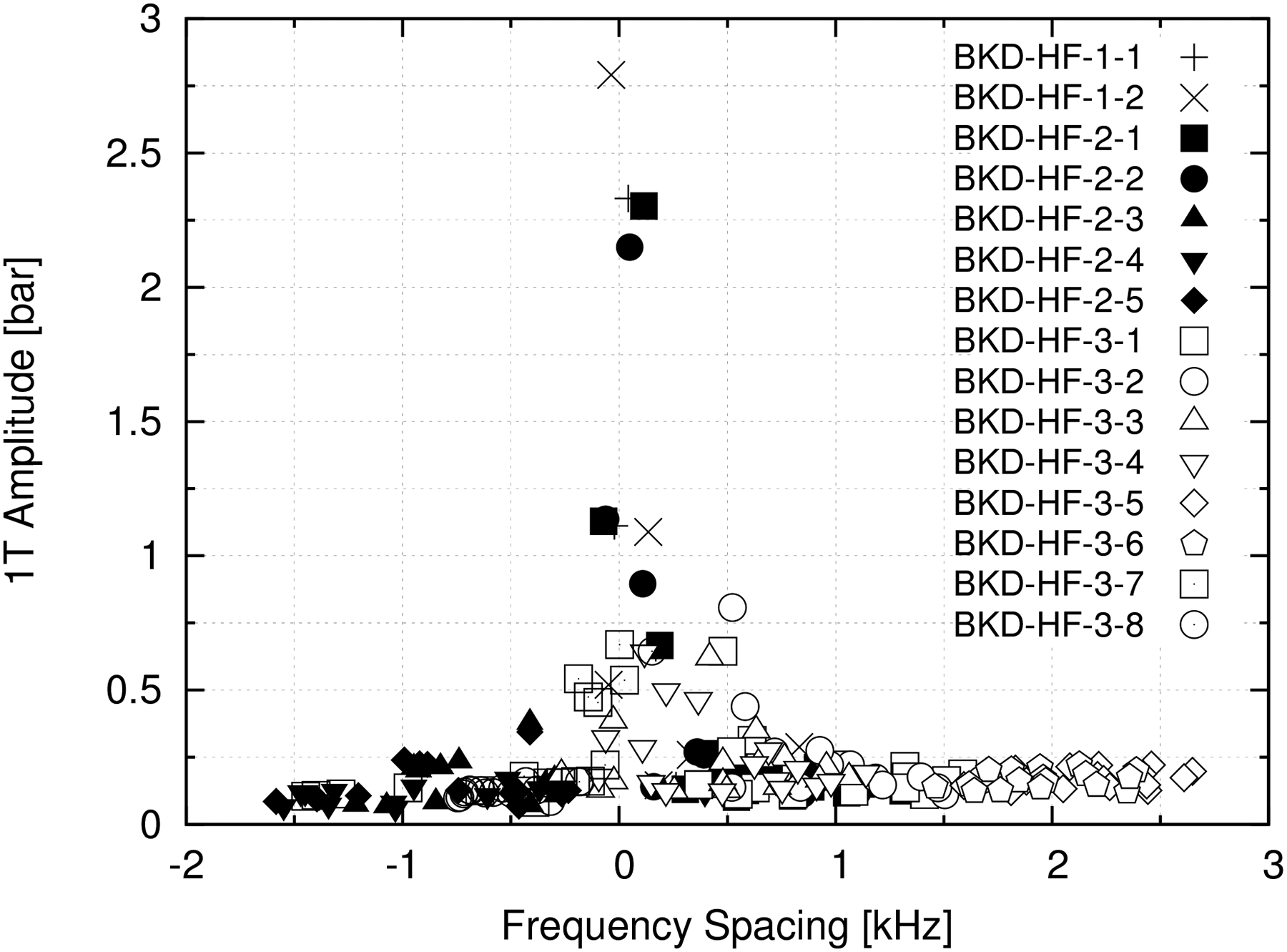
1T mode amplitudes plotted over the frequency spacing between the 1T and the LOX post 2L frequency. 14
It can also be seen in Figure 1 that there are several conditions with a low frequency spacing, but which show no excitation of the 1T mode. For that reason, Gröning 12 described a low frequency spacing as a necessary condition for the instability in BKD, but not a sufficient one. Another interesting aspect of Grönings 12 analysis was, that the LOX post eigenmodes were also excited for stable chamber conditions. Therefore, Gröning 12 argued that the LOX post acoustic needs to have an excitation mechanism, which is independent of the chamber acoustics. Thus, one remaining gap in gaining a better understanding of the excitation mechanism of the instability in BKD is the identification of source of the LOX post acoustic modes. This process could have a positive influence on the flame response at the frequencies of the LOX injectors, which could help to discriminate between stable and unstable conditions that have a very close frequency spacing. Thus, by identifying this additional process, it will hopefully be possible to better define the conditions for an excitation of the 1T mode in this combustor.
Experimental setup and method
Thrust chamber BKD
The tests for this analysis were conducted with the research combustor BKD at the European Research and Technology Test Facility P8 for cryogenic high-pressure combustion. This combustor offers an experimental platform to study self-excited combustion instabilities under representative conditions, including cryogenic propellants, multiple injector elements and combustion chamber pressures exceeding the critical pressure of oxygen. The combustor, as shown in Figure 2, consists of three main elements: injector head, cylindrical combustion chamber segment and a nozzle segment. The chamber diameter is 80 mm. The throat diameter of 50 mm gives representative nondimensional chamber geometry parameters, such as a contraction ratio of 2.56 and a characteristic chamber length of
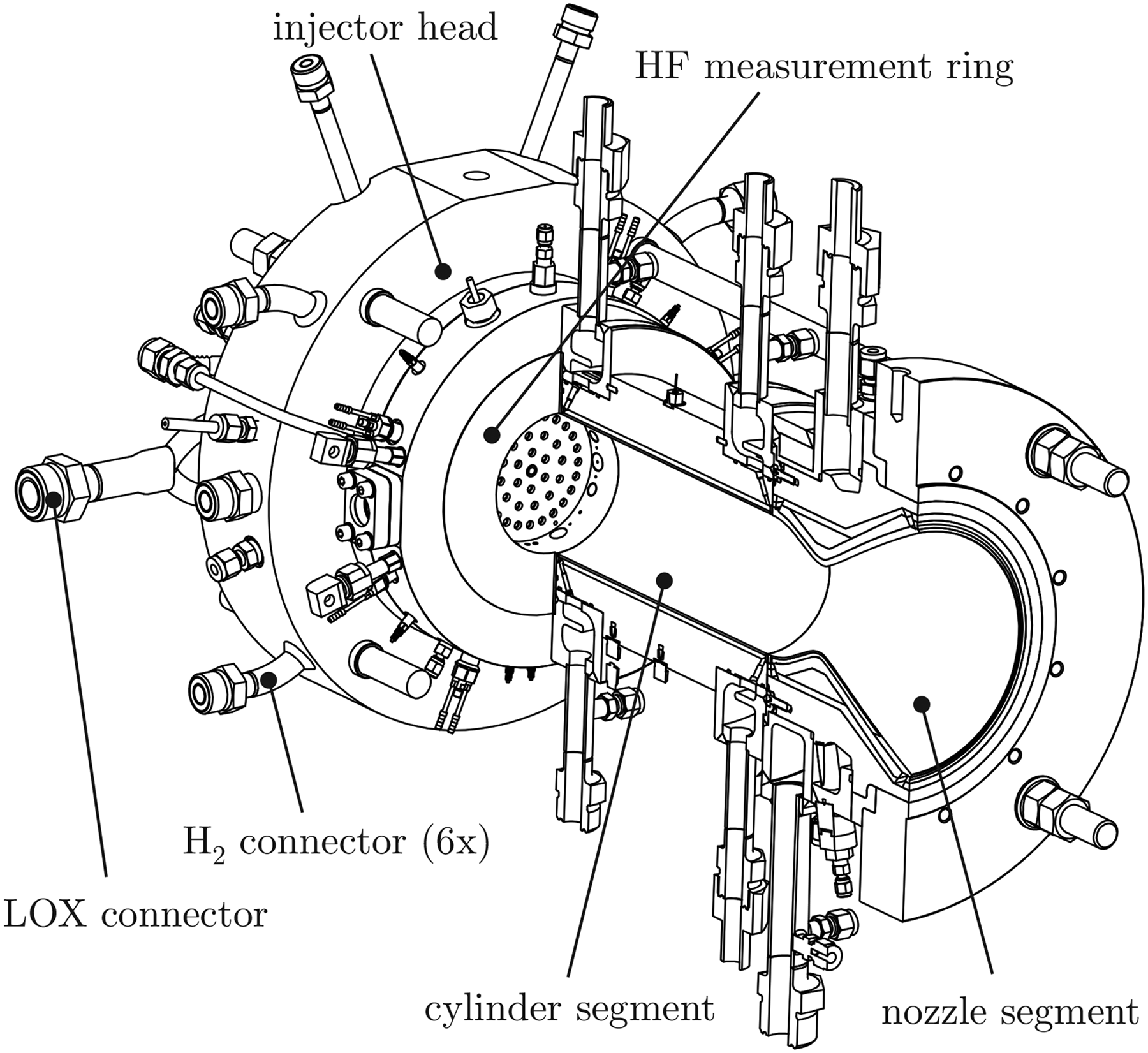
Thrust chamber BKD.
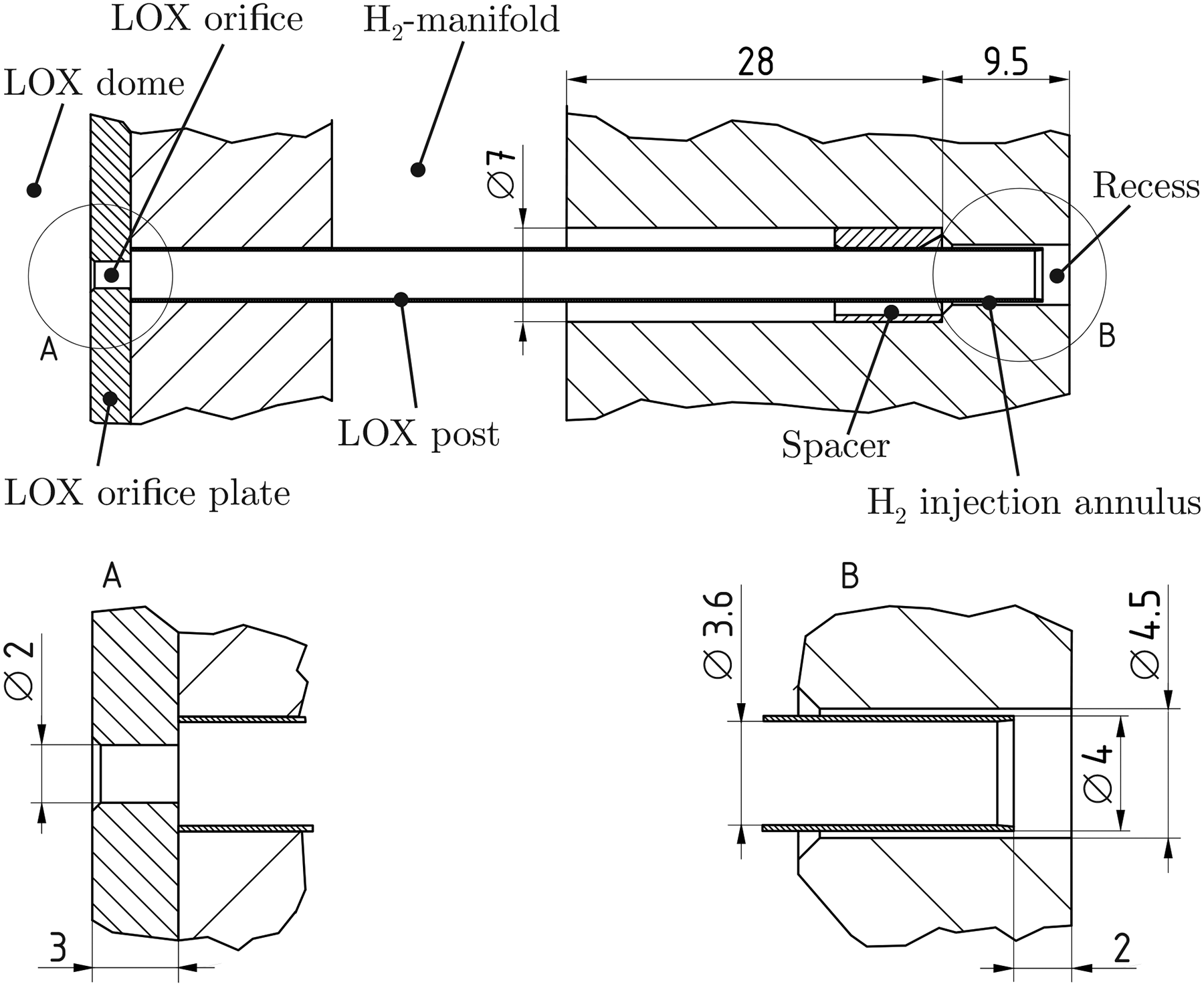
The injector head consists of 42 shear coaxial injection elements with a recessed and tapered LOX post. A drawing of a BKD injection element is presented in Figure 3. Due to a small H
BKD injector element.
Measurement technique
As can be seen in Figure 2, a measurement ring equipped with high-frequency diagnostics was placed between the injector head and the cylindrical segment. BKD can be equipped with different versions of the measurement ring. Initially Gröning 12 used a measurement ring which covered the first 15.5 mm of the combustion chamber. This ring was equipped with eight flush-mounted acoustic pressure sensors (Kistler type 6043A) and specially developed fibre-optical probes, which allowed measurements of the local OH* emissions. Both the high-frequency pressure oscillation sensors and the fibre-optical probes share a common measurement plane, which is placed 5.5 mm downstream of the injection plane.
Within the framework of recent BKD instability investigations, a new version of the measurement ring has been designed. This longer ring now covers the first 25.5 mm of the combustion chamber and therefore needs active water cooling. By implementing the new, longer measurement ring in BKD, the length of the entire combustion chamber increased by 10 mm. This ring, presented in Figure 4, still contains eight acoustic pressure sensors at the same locations as the previous ring.
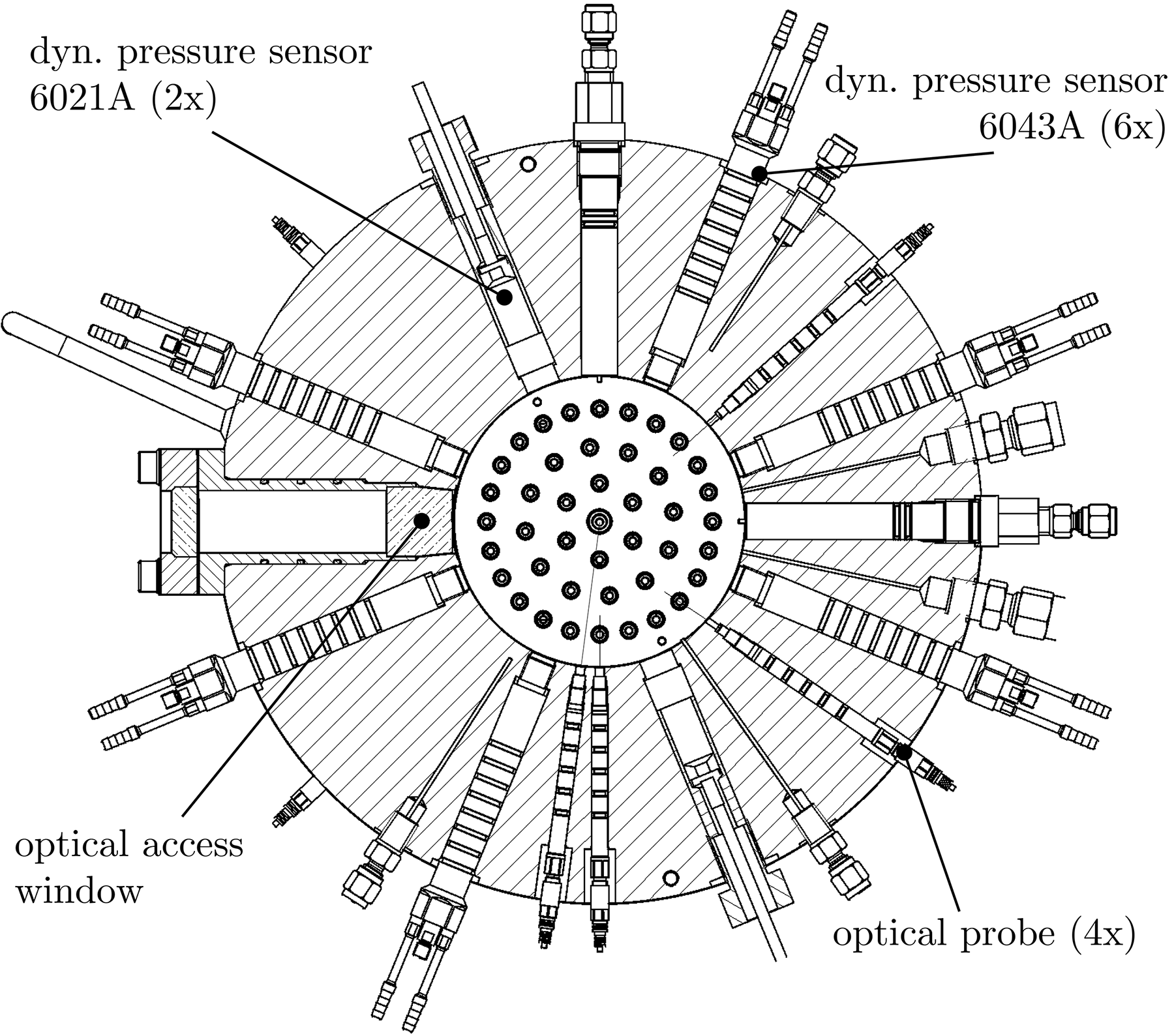
Measurement ring with improved optical access.
The pressure sensors have an angular spacing of 45
The main purpose of the ring modifications was to increase the optical access capabilities in BKD. The most important modification of the new measurement ring, was the capability to place an 18 mm diameter sapphire window, see Figure 4 and Figure 5. This allowed the first 2D flame visualization in a multi-element rocket engine with a self-excited combustion instability at representative conditions, such as cryogenic propellants and supercritical chamber pressures. The investigation of the 2D flame dynamics from the sapphire window have already been published in previous studies.16,17
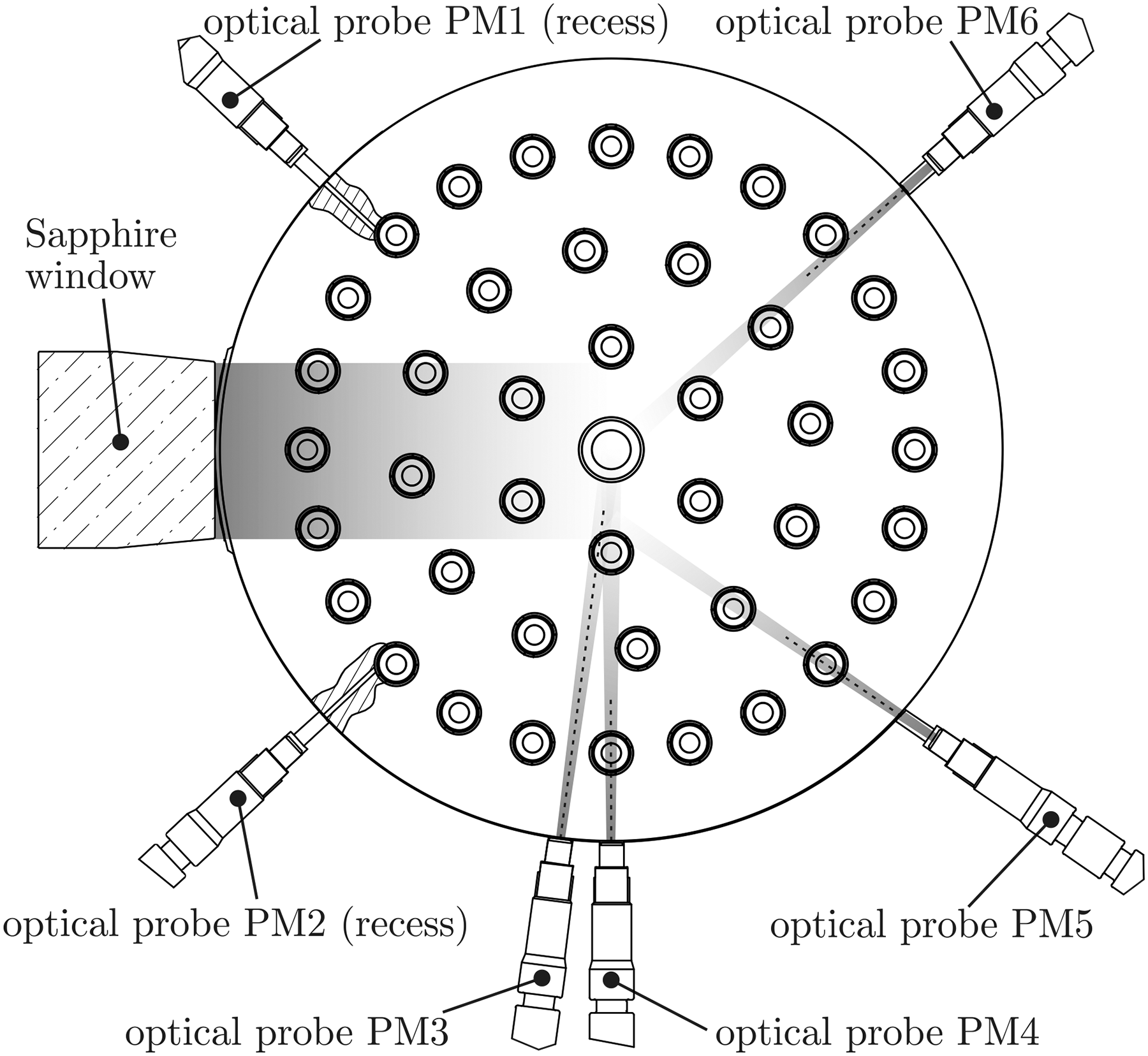
Field of view of the optical components in the measurement ring. The optical probes PM1 und PM2 measure OH* emission from the recess volume of two of the 42 injectors.
However, in this paper the analysis concentrates on the pressure oscillations and the signals from the fibre-optical probes. The probes contain a small sapphire rod through which the radiation is transferred through optical fibres to photomultipliers (PMs). OH* filters (
The new measurement ring still contained four of the fibre-optical probes, which are placed in the measurement plane 5.5 mm downstream of the injection plane. In addition, two optical probes were added, which measure OH* emission through small drilling holes in the faceplate of BKD from the recess volumes of two of the 42 injection elements. These probes (PM1 and PM2) are shown on the left side of Figure 5. The radial drilling holes through the faceplate and into the recess volume have a small diameter of 0.5 mm in order to disturb the flow and combustion inside the recess of these two injectors as little as possible. The centre of the holes is placed 0.5 mm downstream of the LOX post tip, such that the axial distance of 0.25 mm to 0.75 mm of the recess length of 2 mm is optically accessible. A detailed view of the recess volume and the radial drilling hole through the faceplate is presented in Figure 6.
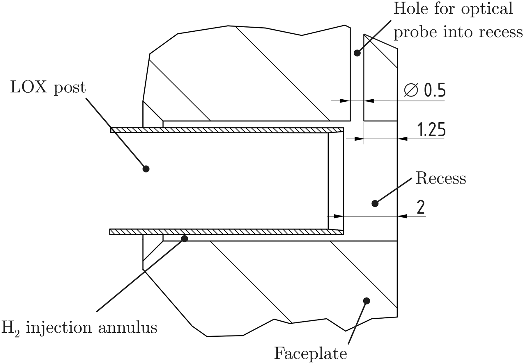
Detailed view of the injector exit and the recess volume of one of the injectors which allow OH* measurements from the recess volume through a radial drilling hole in the faceplate.
Operating conditions
The BKD combustor is operated under representative conditions with respect to European LOX/H
In the conducted test campaigns so far, BKD was operated with different hydrogen temperatures in order to study the impact of
Investigation of flame dynamics in recent BKD stability campaigns
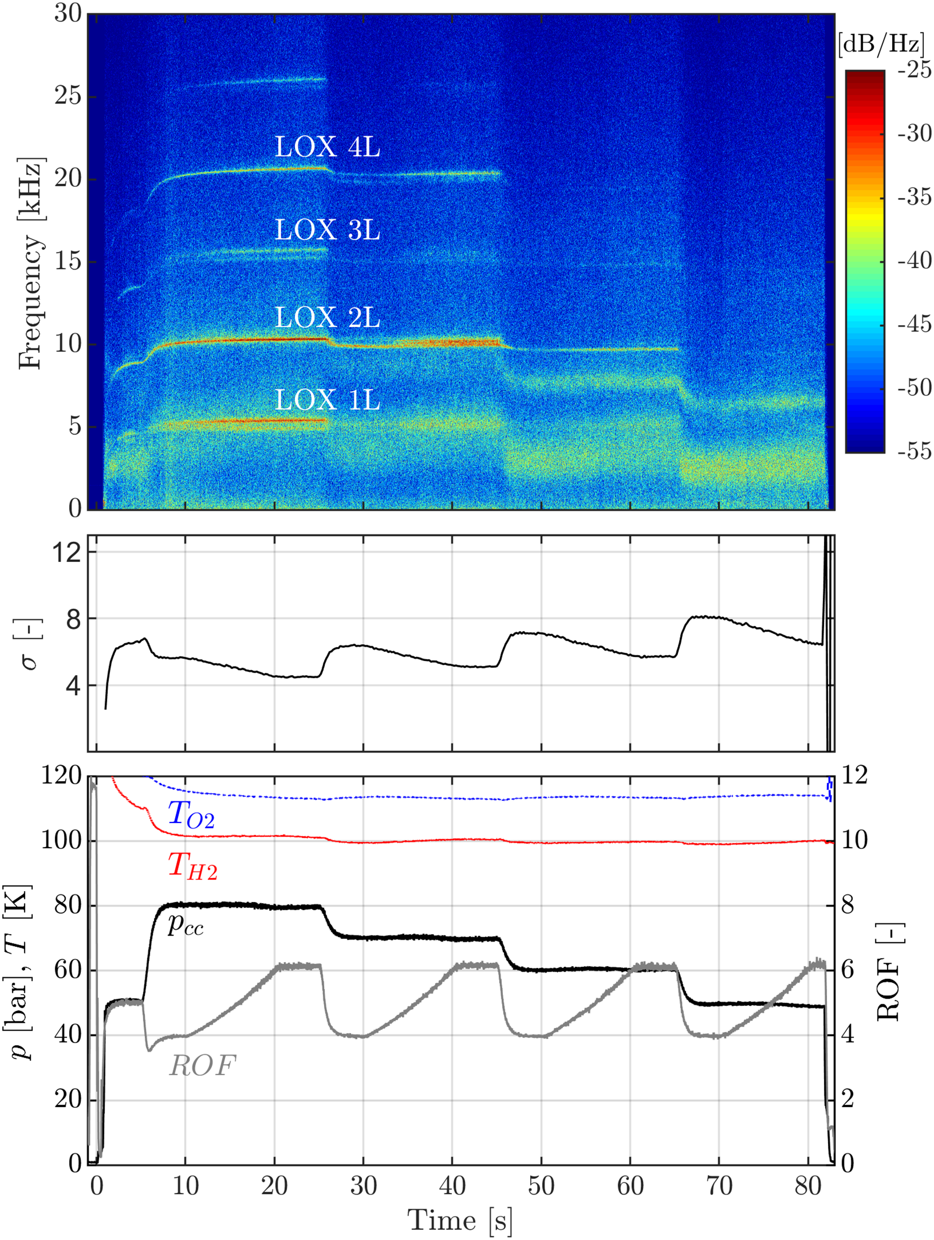
As was described before, the BKD combustor has been modified for improved optical access. With the modified experiment several tests were conducted. Figure 7 shows a spectrogram of the chamber pressure oscillations from a ROF-ramping test sequence of the modified experimental setup of BKD with the optical access measurement ring. For the consistency to the previous studies of Gröning 12 the dB-scaling of the spectrogram is calculated with the reference pressure of 80 bar. It can be observed that the combustion chamber acoustics behave similar to the Gröning tests. 12
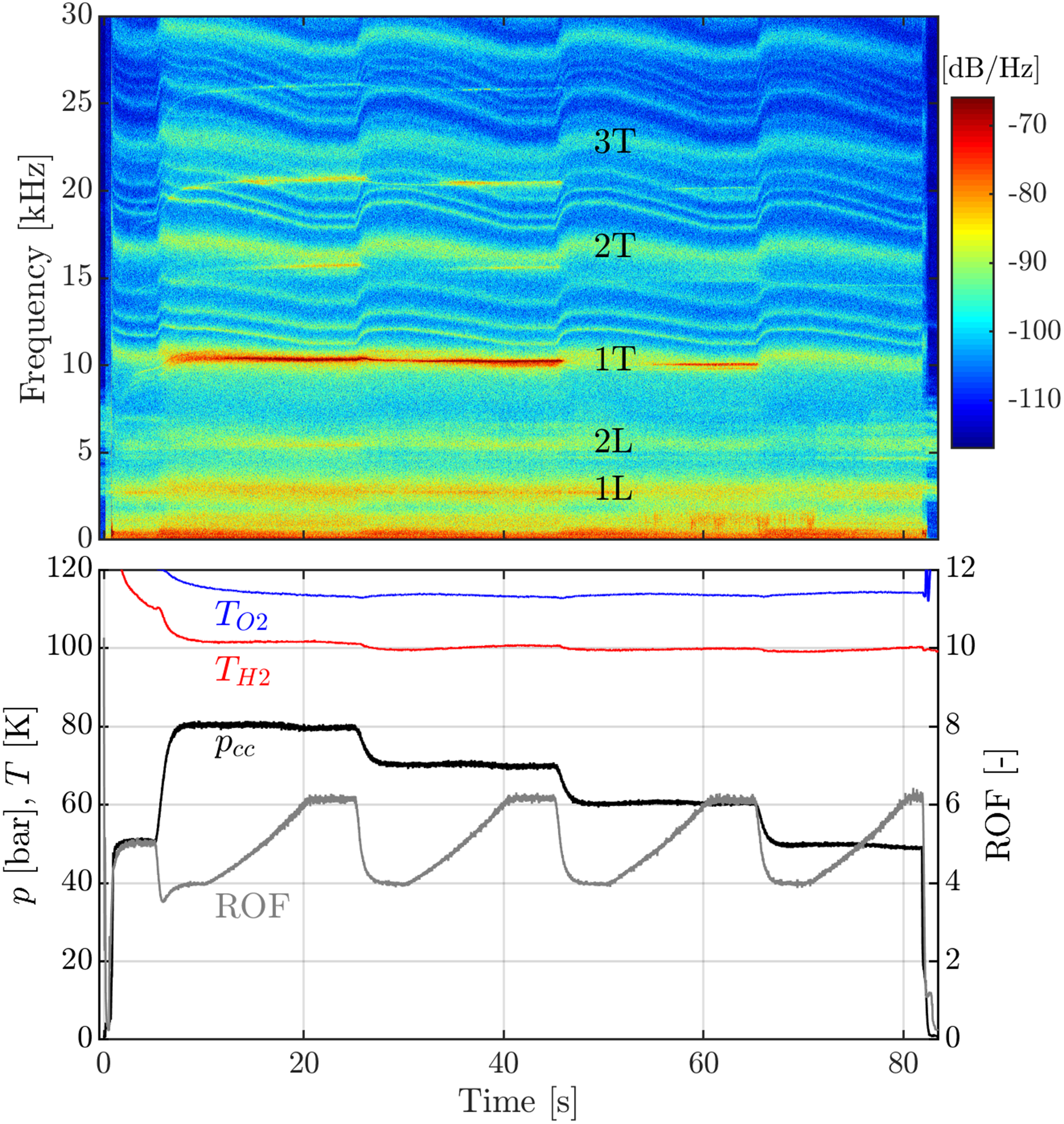
The combustion chamber pressure has only little influence on the chamber acoustics. The chamber mode frequencies are mostly affected by the propellant mixture ratio ROF. An increase of the ROF for each pressure stage leads to a gradual decrease of the acoustic chamber eigenfrequencies. For specific operating conditions (ROF 5 to 6 at higher chamber pressures of 70 and 80 bar) the chamber 1T mode can get excited.
The corresponding combustion dynamics measured through OH* dynamics with the fibre-optical probes in the measurement plane, is presented in Figure 8.
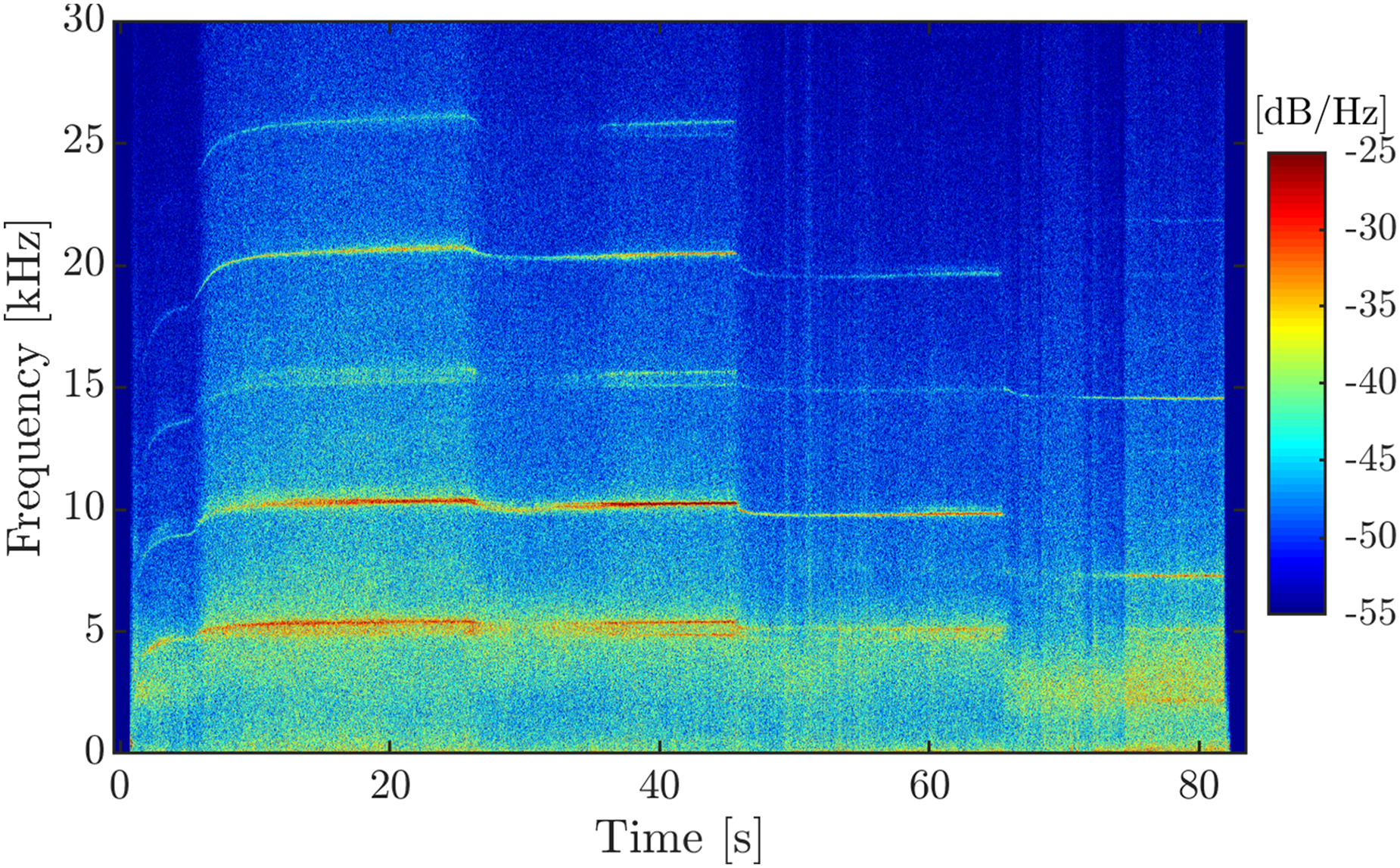
OH*-spectrogram for the ROF-ramping test shown in Figure 7.
Similar to the observations of Gröning 12 the combustion dynamics are dominated by sharp lines at multiples of 5 kHz, which correspond to the LOX post resonant modes. 14 However, similar to the results of the analysis of the flame dynamics through the optical access window in BKD 18 for a low chamber pressure of 50 bar the LOX post lines are no longer present. This dependency of the excitation of the acoustic eigenmodes in the LOX injectors on operating conditions now opens the opportunity to investigate the excitation source of the injector acoustics.
Analysis of the internal excitation mechanism of the LOX post acoustics
In this chapter, the theoretical excitation sources of injector acoustics, described in the introduction, will be investigated for the combustion chamber BKD operated with LOX/H
Combustion noise
In turbulent combustion, a broadband combustion noise is permanently present.19,2,20 These stochastic pressure fluctuations can weakly excite the acoustic eigenmodes of the system.12,19 According to Gröning, 12 turbulent combustion noise is therefore a possible source of excitation of the excited injector eigenmodes. However, in the framework of recent BKD test campaigns with optical access, it was shown that at a low combustion chamber pressures of 50 bar, the modulation of the combustion dynamics by the LOX-post eigenmodes wasn’t observed. 18 At first, this observation seemed to be contradictory to Grönings observations, 12 in which it was described, that the LOX posts are permanently excited. However, Gröning 12 mostly investigated load points with chamber pressures ranging from 60 to 80 bar. Also, in Grönings BKD test runs, it can be observed, that the amplitudes of the LOX post lines decrease with decreasing chamber pressure. They are strong for 70 and 80 bar and only weakly present for 60 bar. A similar behaviour can be observed in Figure 8. At a pressure of 50 bar the lines can no longer be observed.
Figure 9 compares the relative noise intensity in BKD for different operating conditions. In the power spectral density (PSD) calculation, the respective mean combustion chamber pressure was used for the dB-scaling.
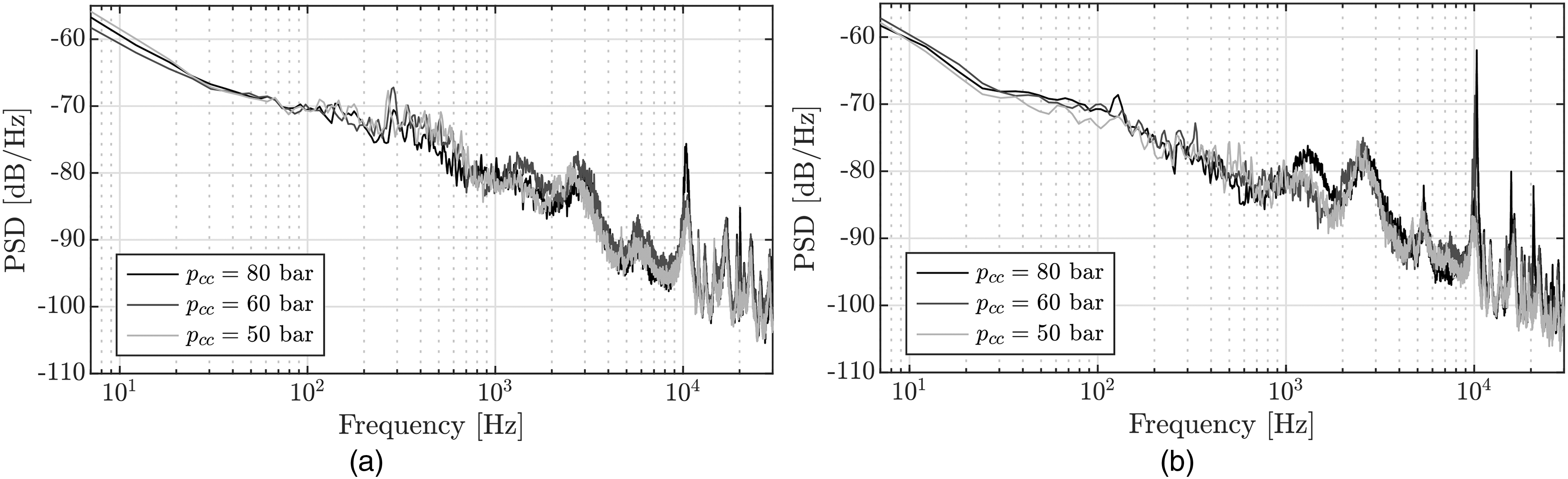
PSDs of pressure oscillations inside the BKD combustion chamber for different operating conditions.
As can be seen in the two diagrams, the load points at different combustor pressures have a comparable, relative combustion noise level. This can be seen in the curve of the PSDs up to the first combustion chamber mode (1L at about 2.5 kHz) and also in the frequency intervals between the combustion chamber modes. Apart from the 1T mode at 10 kHz, which is known to be unstable for
Cavitation
Klein et al.
7
described that the injection-coupled combustion instability in a LOX/LNG combustor was related to the two-phase flow of the injected LOX. Another recent studiy also reported a connection between low-frequency combustion instabilities in a rocket engine with two-phase flow effects in the injection system.
21
In laboratory experiments with pipe flows of water
22
and cryogenic nitrogen,
23
cavitation effects at orifices were found to be an acoustic source. Thus, cavitation in the LOX orifice could also contribute to acoustic excitation of the LOX injector tubes. As shown in Figure 3, the LOX in BKD also flows from a larger dome volume through a sharp-edged orifice into the post. The probability of cavitation is usually estimated with cavitation numbers. Here, the definition of the cavitation number given by Testud et al.
22
was applied to the flow conditions of the LOX orifice in BKD, see Eq. 1. Cavitation occurs for
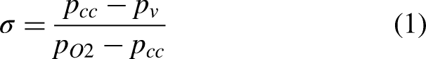
Cavitation number
For all steady-state operating conditions the calculated cavitation numbers are
Varying flame anchoring positions in the injector recess
In a single injector experiment by JAXA, LOX injector coupling was observed in experiments with gradually decreasing hydrogen injection temperatures. It was hypothesized by the authors that different combustion modes in the recess are related to the excitation of instability. 11 Similarly, Hulka and Hutt 6 describe that in the case of the J-2S, the recess volume acted as an amplifier of the LOX post oscillations. Gröning 12 also pointed out that combustion in the recess is a possible source of excitation of the LOX post modes in BKD. In BKD tests with the propellant combination LOX/LNG, injector-coupled combustion instabilities occurred in a configuration with recess, whereas no instabilities occurred without recess. 8 In this study also evidence was presented, that depending on the injection condition both lifted and anchored flames can be present with LOX/LNG combustion.
For the LOX/H
As already observed by Gröning,
12
the signal of the optical probes in the measuring plane of the measuring ring in BKD drops to almost zero at times during cold hydrogen (LH) injection temperatures. Gröning
12
could not conclusively elucidate this effect, but pointed out that this could be explained by lifted flames or by blocked probes. The temporary blockage of the optical probes during cold H
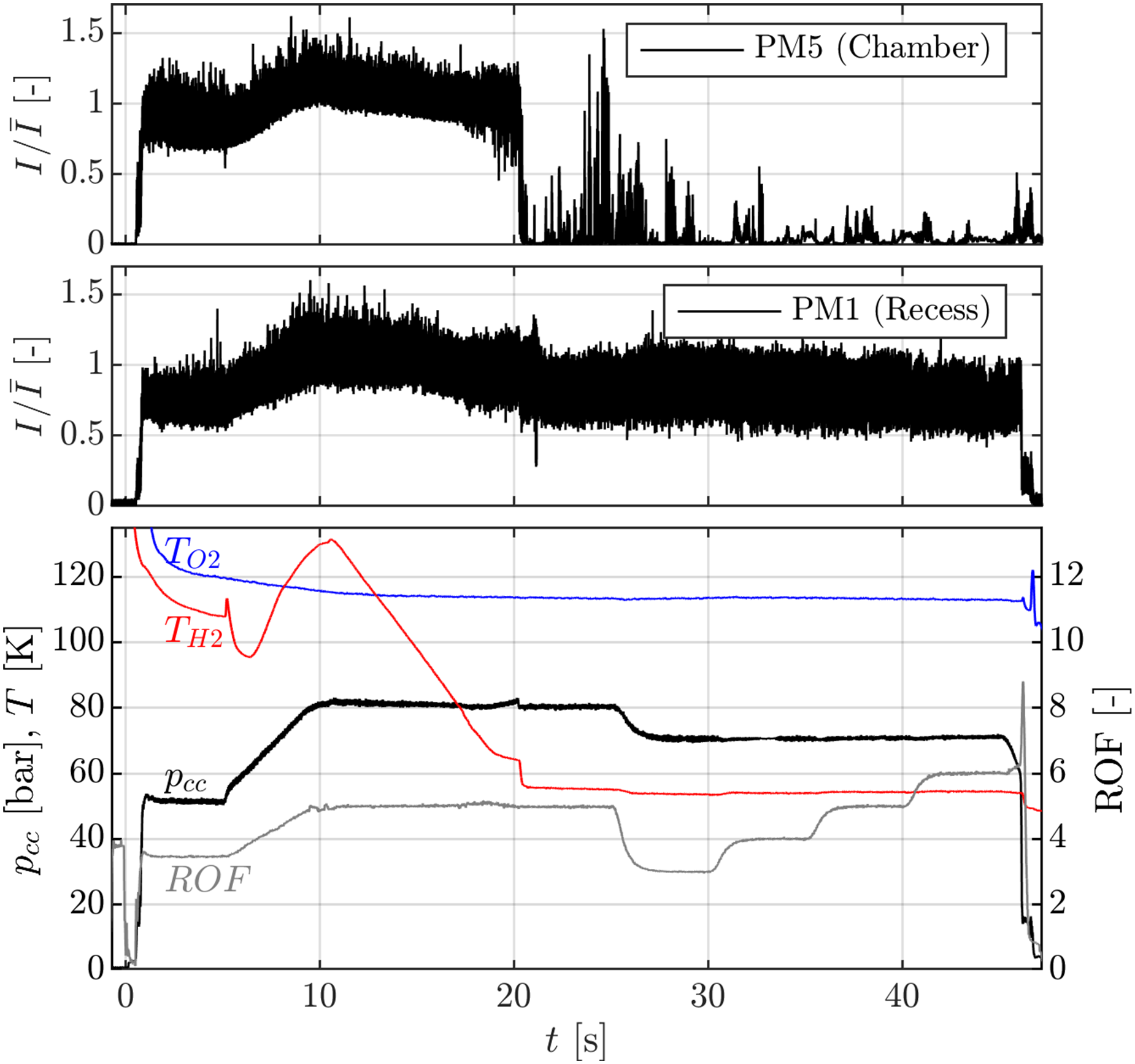
Comparison of the optical probe signals from the combustion chamber (top) and the recess region (middle) for a hydrogen-temperature-ramping test with BKD.
In the middle diagram of Figure 11 the OH* signal of an optical probe from the recess volume at the position PM1 can be seen. This signal does not stop at 20 s, but continues to record significant OH* emission intensities until the combustion chamber is shut off. The results therefore represent strong evidence that the flames anchor consistently at the LOX post even in the presence of cold hydrogen. This is consistent with Gröning’s conclusion,
12
in which it is also pointed out that there is no other experimental evidence of lifted flames in BKD. Furthermore, aside from the hypothesis of Nunome et al.
11
, to the authors’ knowledge there exists no other experimental study which reported lifted flames for LOX/H
Combustion dynamics in the recess volume
As was presented, lifted and anchored flames and thus combution or no combustion in the recess volume cannot be the source for the LOX post acoustic eigenmodes. Next, the combustion dynamics in the recess volume will be investigated. Figures 12 and 13 show spectrograms from the two optical probes, which measure the OH* dynamics in the recess volume in the ROF ramping test.
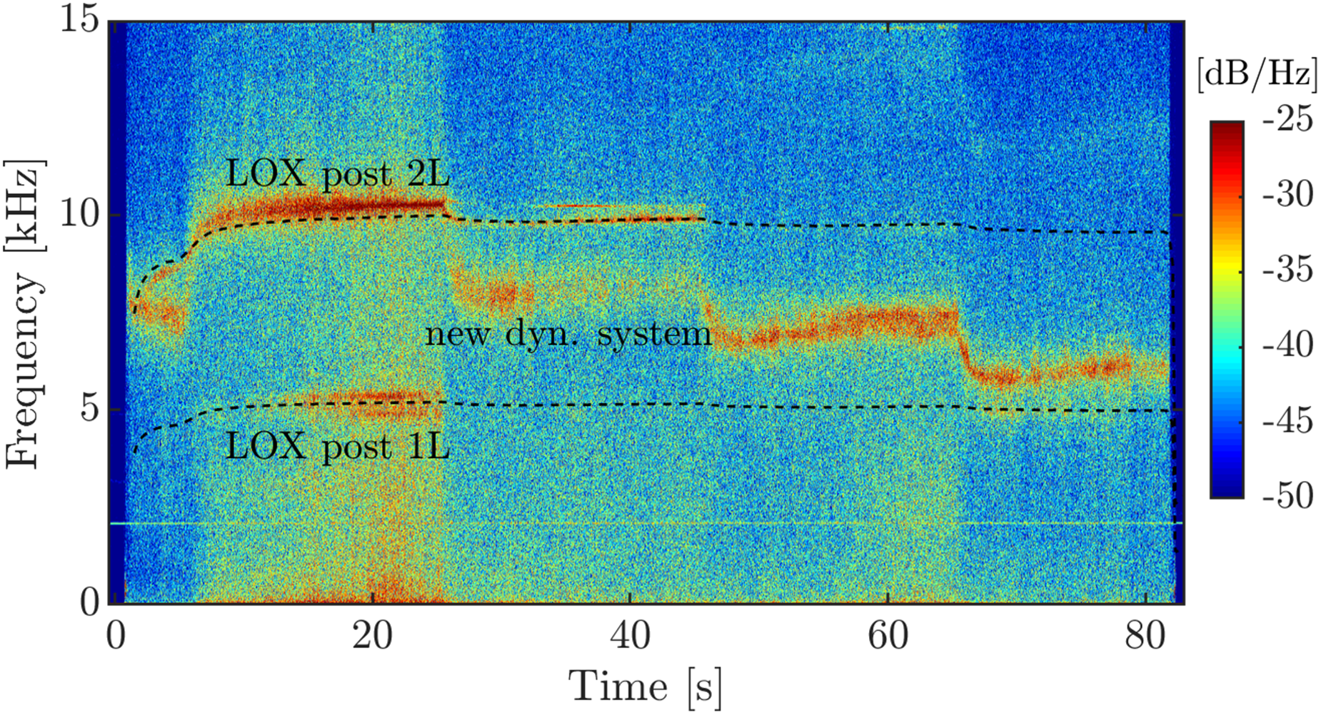
OH*-spectrogram of the optical probe PM1 in the recess volume during the ROF-ramping test, shown in Figure 7.
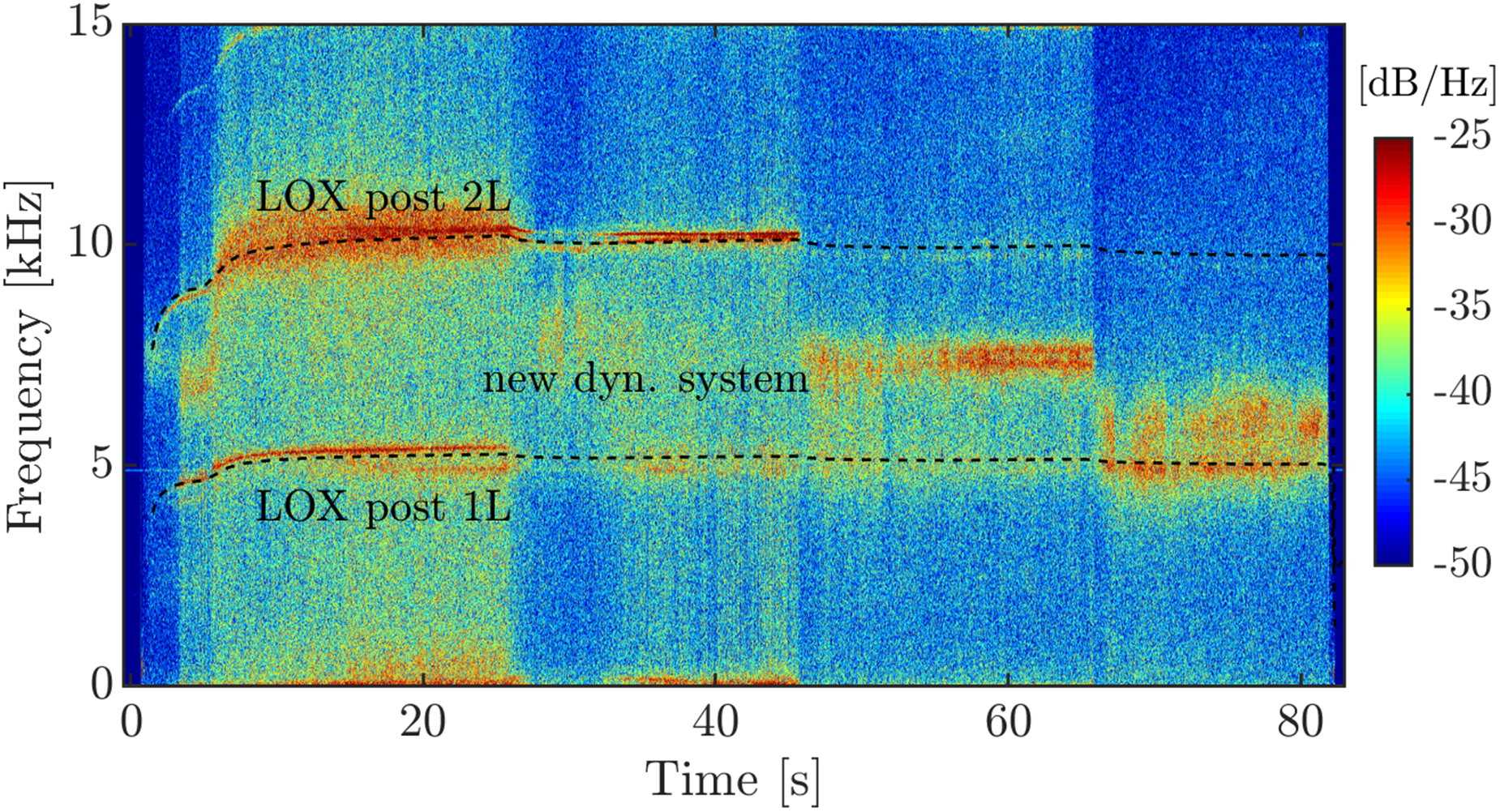
OH*-spectrogram of the optical probe PM2 in the recess volume during the ROF-ramping test, shown in Figure 7.
For 80 bar chamber pressure the dominant LOX post lines at multiples of 5 kHz can be observed. This confirms, that the modulation of the combustion by the acoustic eigenmodes of the LOX injectors already exists in the recess. However, for the lower chamber pressure between 50 and 70 bar the LOX post lines at 5 kHz and 10 kHz get weaker and eventually even fully disappear. Instead, a new dynamic system can be observed, which has not yet been detected in previous studies about the BKD instability.
This new dynamic system shows a step-wise reduction of frequency with decreasing chamber pressure. For each constant chamber pressure, the frequency follows the ROF-ramps. Since the speed of sound in the combustion chamber reduces with increasing ROF, while the new dynamic system shows the opposite dependency on ROF, this new frequency content cannot be resulting from the chamber acoustics. Therefore, it is investigated next, if this new frequency content can be explained by acoustic oscillations in the injection system. Figure 14 shows the temporal behaviour of the speed of sound of the propellants in the injector head. Since in the investigated test run, the propellant temperatures are kept almost constant, the speed of sound in the injection system doesn’t show large variation. When steady state conditions are achieved at about 5 s both
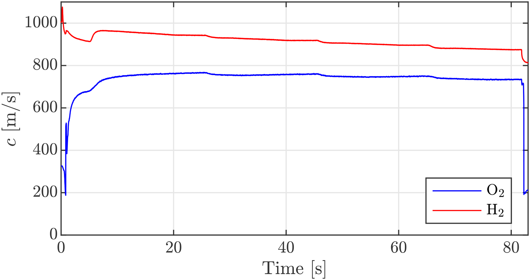
Temporal evolution of the speed of sound of the propellants in the injector head for the ROF-ramping test.
In contrast, the new dynamic system observed in the recess region reduces from more than 8 kHz at the 80 and 70 bar pressure stages to less than 6 kHz for 50 bar. The frequency variation over the test duration is therefore more than 40%. Therefore, neither, the LOX, nor the hydrogen speed of sound correlate with the newly detected dynamic system in the recess volume. Thus, these oscillations cannot be of acoustic origin.
Hydrodynamic effects
Since the new frequencies in the combustion dynamics of BKD cannot result from acoustic oscillations, it is investigated next if they can originate from hydrodynamic modes which originate from periodic vortex shedding. Combustion does not only react sensitively to acoustic perturbations, but can also respond to flow dynamics, such as periodic vortices, which increase the mixing locally and also lead to a fluctuation of the heat release rate. In solid rocket motors periodic vortex shedding at transitions between segments or due to curvatures in the propellant grain are one of the main excitation sources of combustion instabilities.1,26 Several experimental27–31 and numerical studies28,13,32–35 also show that hydrodynamics effects can be related to oscillations of the heat release rate and the pressure in the combustion chamber. Culick 27 states that is has been known since the 50s, that periodic vortex shedding can excite the acoustic resonant modes of the combustion chamber.
According to Tsohas and Heister 13 it is commonly known that the dynamic processes in the injectors are major contributors to combustion instabilities in liquid propellant rocket engines. Figure 15 shows the different hydrodynamic processes that can appear in a liquid propellant rocket engine shear coaxial injector element based on the study of Tsohas and Heister. 13 These effects can potentially interact and amplify acoustic oscillations in the injectors or lead to modulated injection rates and hence play a role within high-frequency combustion instabilities.
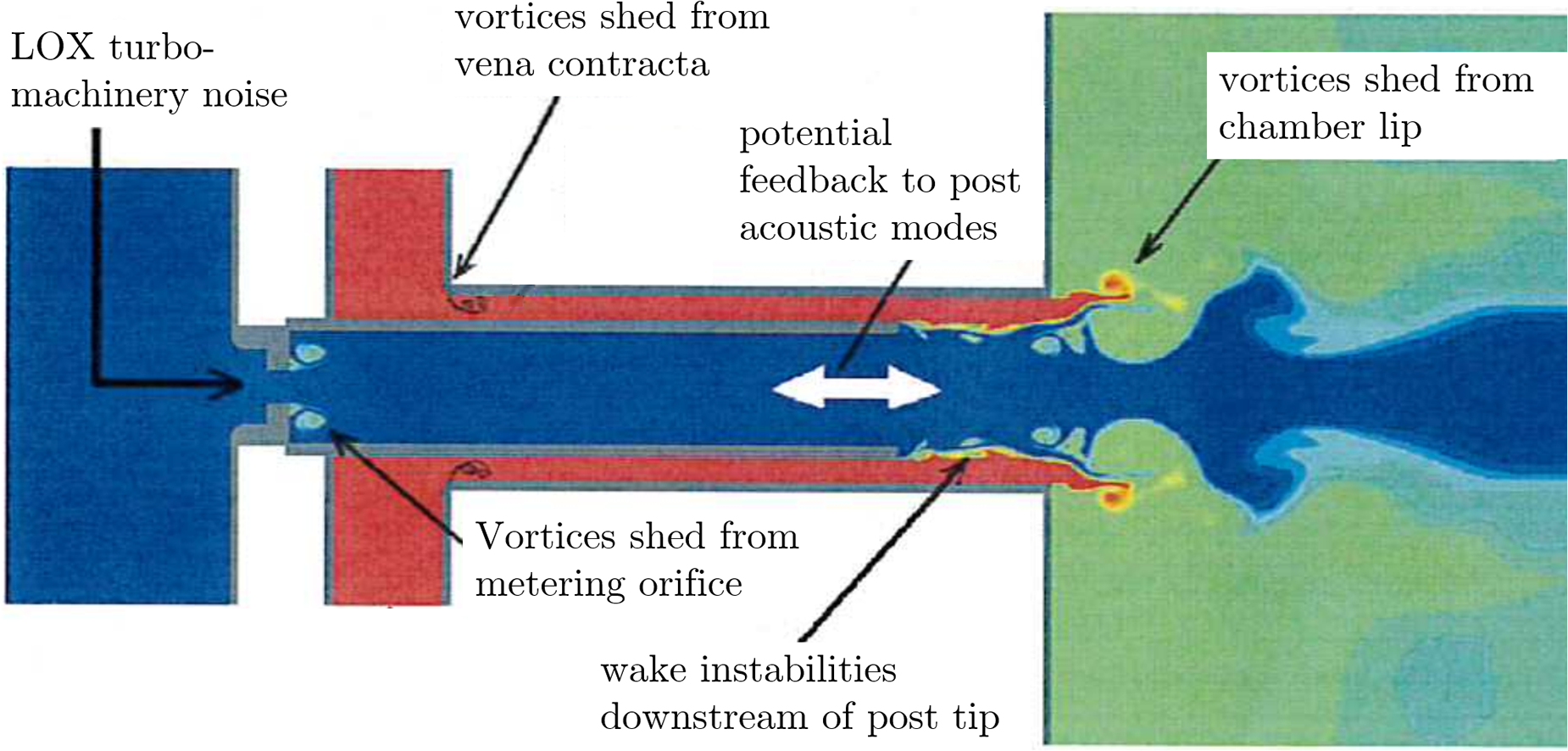
Hydrodynamic processes in a shear coaxial injection element. Modified from Tsohas and Heister. 13
Within hydrodynamics the shedding frequency is thereby depending on the flow velocity
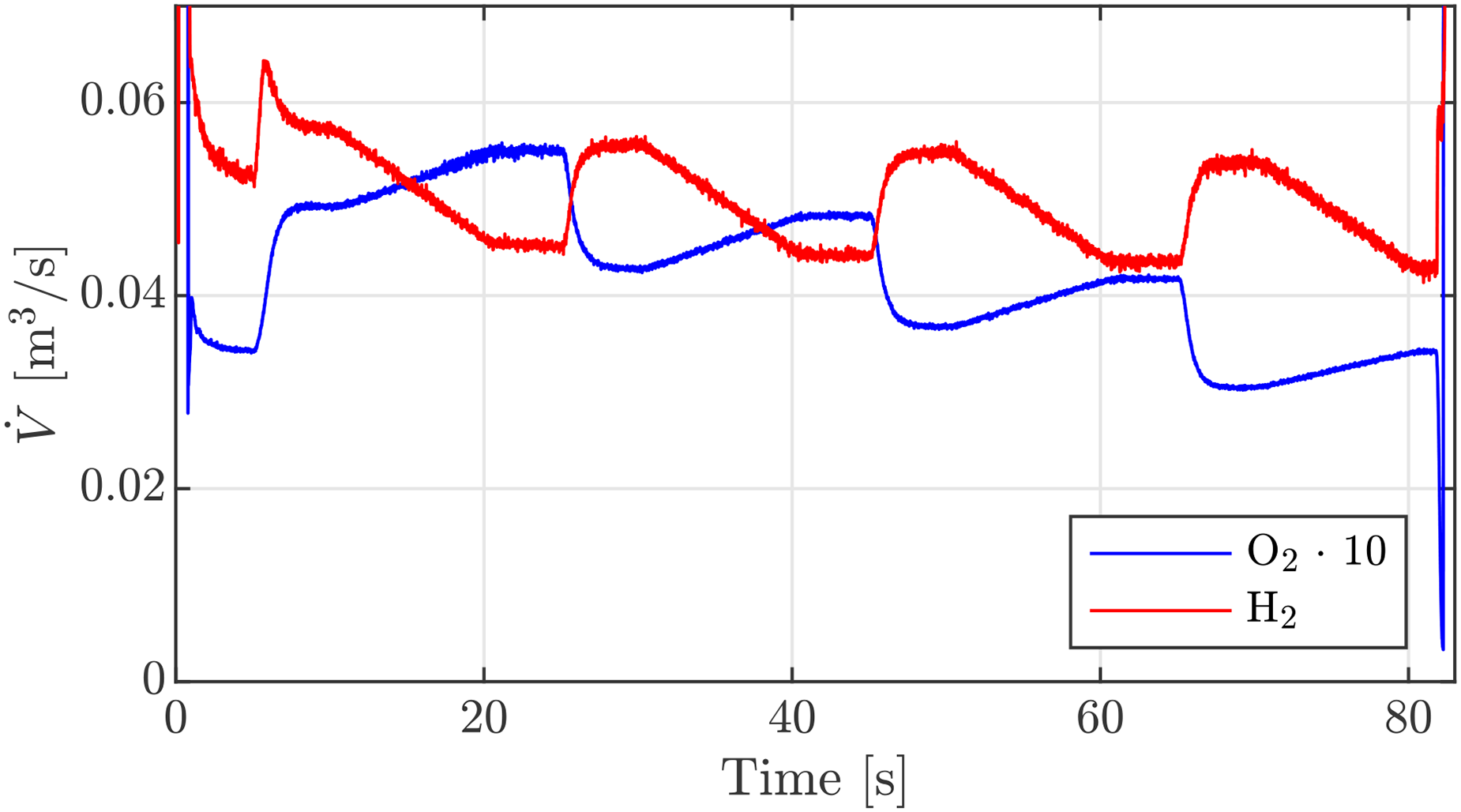
Volumetric flow rate of the propellants in the injection system during the ROF-ramping test.
Based on the observation, that the dynamic system in the recess volume only correlates with the LOX volumetric flow, only hydrodynamic effects in the LOX injection system are considered. Possible hydrodynamic processes of the LOX injection are the natural jet instability of the liquid LOX jet36,34,35, wake instabilities at the LOX post tip13,28,33, the sudden increase of the cross-sectional area from the LOX post inlet orifice into the LOX post, which is known in literature as a backward facing step (BFS)37,28,38,39 and the so-called orifice whistling of the inlet orifce.22,23,40–45 The detailed definition of the Strouhal numbers and the Strouhal number ranges of maximum amplification can be found in the given references.
Table 1 summarizes the Strouhal number ranges for the aforementioned investigated hydrodynamic effects and the estimated frequency which could get excited by the effect. The corresponding frequency of each effect was calculated for the mean Strouhal number of the given ranges and the LOX flow velocity of the most unstable load point of BKD, which is 80 bar ROF 6 at GH injection conditions.
Overview of potential hydrodynamic effects in the BKD LOX injection system and the estimated frequency of maximum amplification estimated for the most unstable load point of
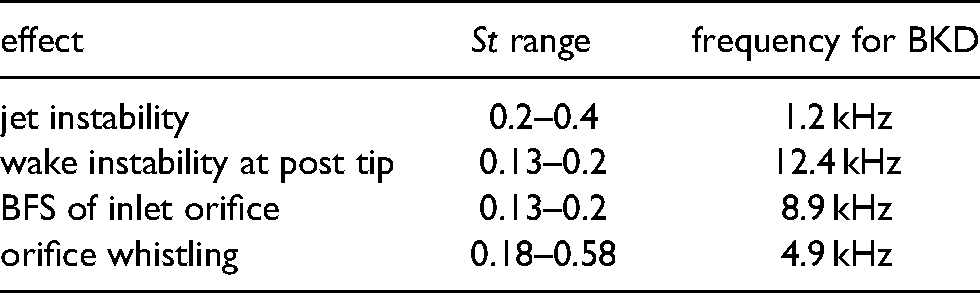
The frequency of the natural jet instability of the liquid oxygen is with 1.1 kHz too low to either be responsible for the new dynamic content in the recess volume nor the excitation source of the LOX post acoustics. In addition, the wake instability frequency at the LOX post tip is too high. The best matching frequencies seem to be resulting from the vortex shedding at the LOX inlet orifice. Thereby the orifice whistling frequency comes close to the 1L mode of the LOX post and could therefore potentially amplify this mode. Furthermore, within the rocket propulsion community it is known that badly designed injector orifices can lead to flow or combustion instabilities.2,46
Due to limited diagnostics in the BKD injection system, a definitive experimental proof of which hydrodynamic effect leads to the acoustic excitation of the LOX post eigenmodes unfortunately cannot be presented. Nevertheless, an effect known as “orifice whistling” is currently the most likely candidate for the observed frequencies in the PM spectrograms. This effect can excite acoustic oscillations in pipes up- or downstream of sharp-edged orifices and the calculated Strouhal number is in a range, for which several publications reported an acoustic excitation through the flow through short orifice holes.22,23,40,41,43,44,42,45 It should be mentioned that actual orifice geometry of BKD with a length to diameter ratio of about 1.5 falls in the range between short and long orifice holes for which only little information about the whistling potential has been published. For that reason, in this study it is assumed that the Strouhal number range of orifice whistling of short holes is applicable to the BKD injector orifice as well. However, this assumption should be investigated in future studies.
Nevertheless, a coupled CFD/CAA analysis of the BKD instability by Schulze 47 mentioned unexpected vortical structures downstream of the LOX injector orifice and that they could interact with the LOX post resonant modes in BKD. Another numerical study of the LOX injector flow of BKD also showed that vortical structures appear in and downstream of the orifice and are able to excite the acoustic resonant modes of the post without any additional external forcing. 48 Besides, an experimental investigation of the intra-injector dynamics conducted with water-flow and an optical accessible inlet orifice further revealed that the longitudinal acoustic resonance modes downstream of the inlet orifice can get excited by the orifice flow dynamics for the right flow conditions. 24
Figure 17 shows a spectrogram of the OH* oscillations measured through a fibre-optical probe in the measurement plane during the ROF-ramping test run. Overlaid are the first two LOX post eigenmodes via the dashed lines. In addition, the calculated whistling frequencies for
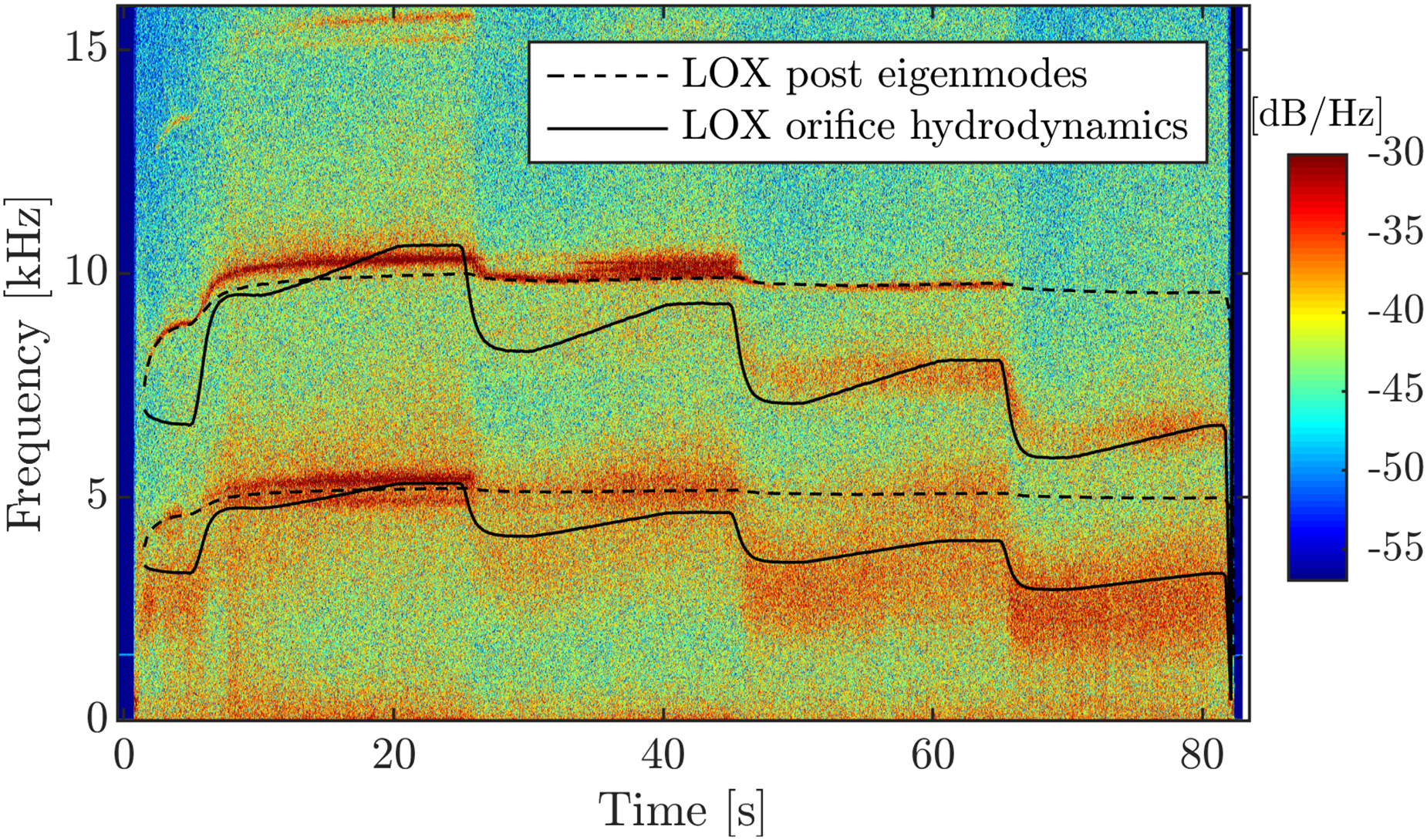
OH*-spectrogram of the optical-probe PM5 during the ROF-ramping test with indicated hydrodynamic frequencies for
It can be observed that there is a broadband peak correlating with the prediction of the orifice whistling frequency. Besides, it is also evident that the LOX post eigenmodes get excited when the vortex shedding frequency is close to the acoustic eigenfrequencies. This dependency is further investigated and the results are shown in Figure 18. Here the OH* oscillations from the fibre-optical probes in the measurement plane are bandpass-filtered around the 1L mode of the LOX post and normalized. The 1L mode of the LOX post is considered, because compared to the LOX post 2L mode its oscillation is not influenced by the chamber 1T mode. However, it is assumed that if the LOX post 1L mode is getting excited by a hydrodynamic effect, this will also excite the relevant overtone (2L) which is known to lead to the combustion instability in BKD 14 . The ROF ramping test run is separated into time windows with 0.2 s length and for each time window the Strouhal number of the LOX post 1L mode based on the orifice length and LOX flow velocity in the orifice is calculated. The grey background indicates the Strouhal number range for orifice whistling for short circular holes according to literature.22,23,40,41,44,43,42,45 It can be observed that the highest oscillation amplitudes with the LOX post 1L mode appears for Strouhal numbers around 0.35. For Strouhal numbers above the typical whistling range, the OH* oscillations are weaker, thus indicating that the LOX post acoustics are amplified by a hydrodynamic effect.
LOX post 1L mode filtered and normalized OH* oscillation amplitude from the measurement plane plotted over the calculated Strouhal number of the LOX post 1L mode based on the orifice flow for the ROF ramping test.
Thus, the periodic vortex shedding of the LOX inlet orifice can explain both the newly detected frequency content in the combustion dynamics in BKD and the excitation source of the LOX post acoustics.
Excitation processes of the combustion instability in BKD
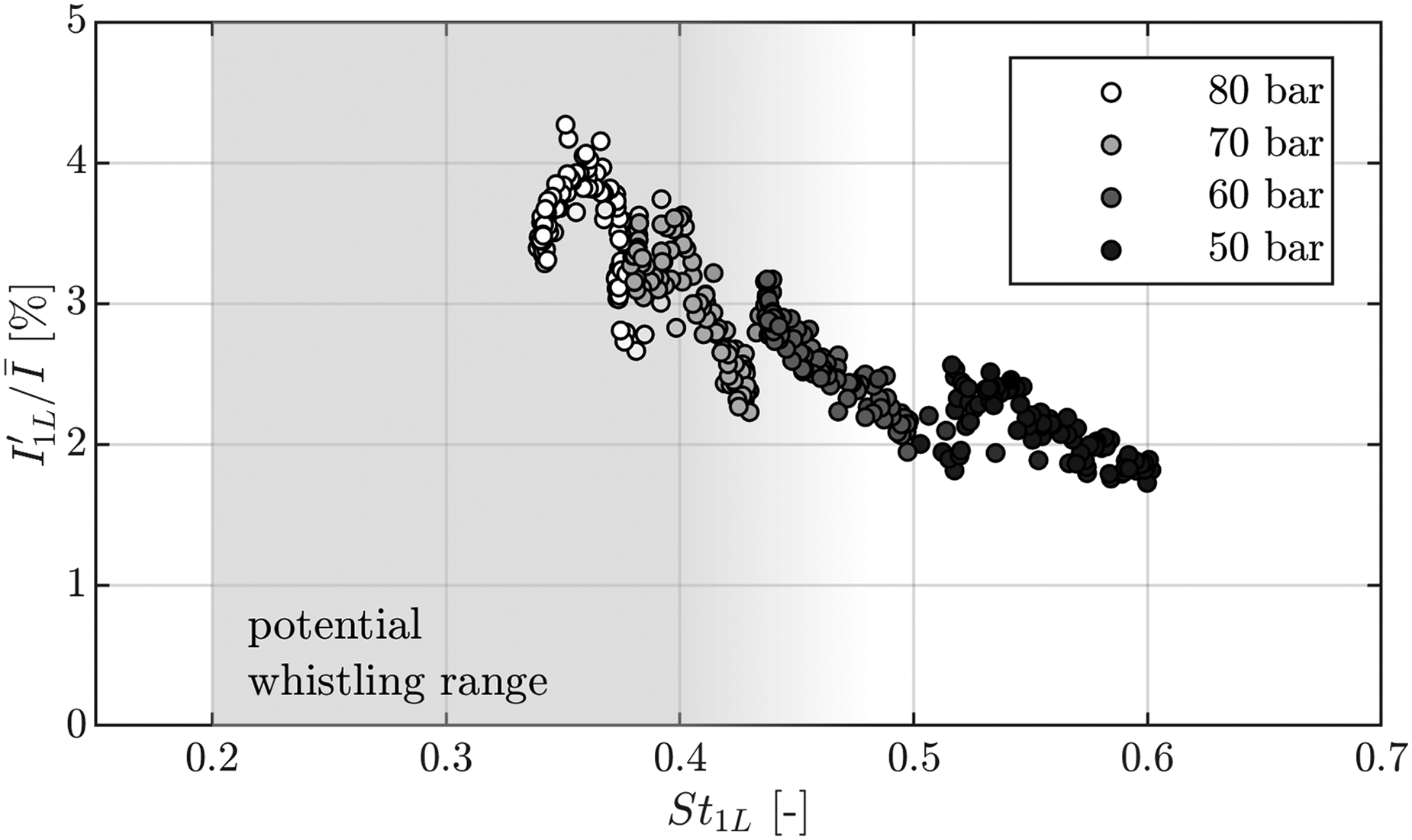
Now that the excitation source of the LOX post acoustics has been identified to be resulting from periodic vortex shedding in the LOX injection system, it can be analyzed if this additional condition for the LOX post excitation can now better explain the condition for the excitation of an instability in BKD. From the aforementioned analysis it can be expected that the strongest excitation of the LOX post resonance modes appears for Strouhal-numbers around 0.3 to 0.4 in BKD. It can, for that reason, also be expected that the highest injection-driven 1T-mode amplitudes also appear for these Strouhal-numbers. Figure 19 shows the 1T-amplitudes for different operating conditions plotted over the Strouhal number of the LOX injector orifice calculted for the 1L mode of the injectors.
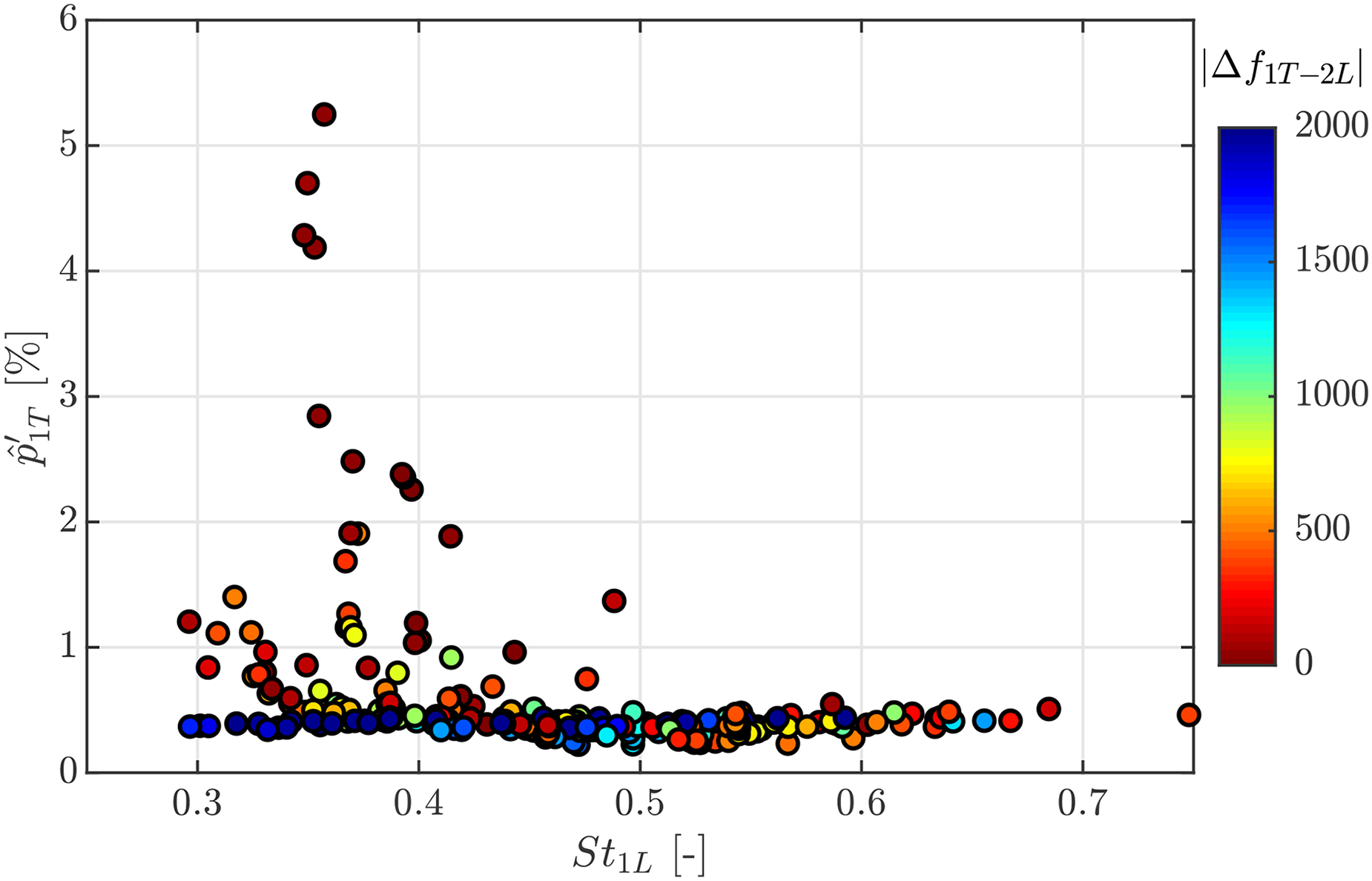
Amplitude of the 1T mode plotted over the Strouhal-number of the LOX post orifice calculated. The colour of the symbols shows the absolute value of the frequency spacing between the chamber 1T mode and the LOX post 2L mode.
It can clearly be observed that the highest 1T-amplitudes appear for Strouhal-numbers between 0.3 and 0.4. In addition, the filling colour of the scatter points indicates the absolute value of the frequency spacing between the chamber 1T mode and the LOX post 2L mode. In agreement with the results of Gröning et al.
14
the other condition for the excitation of the 1T mode is a close
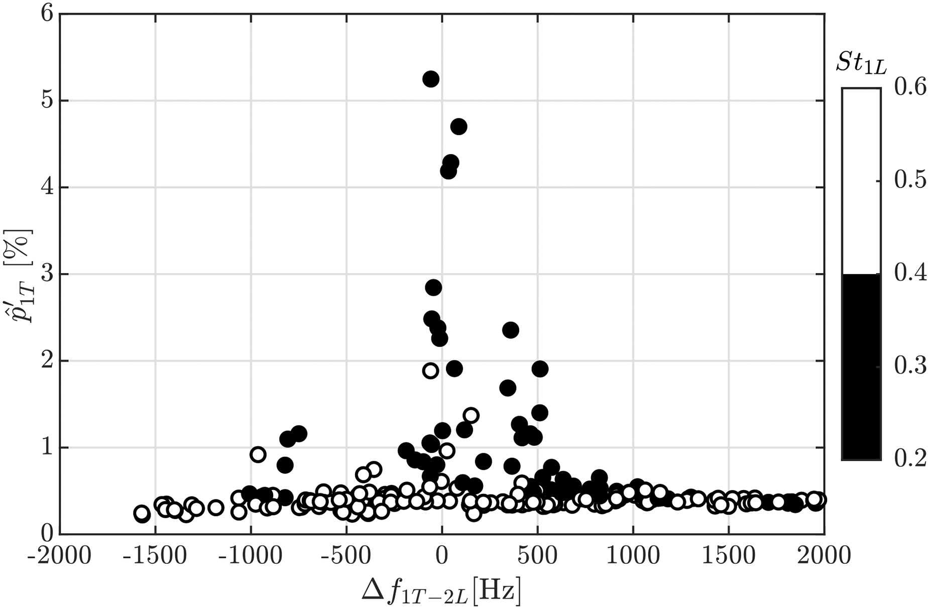
Amplitude of the 1T mode as function of the frequency spacing to the LOX post 2L mode and the Strouhal number of the LOX inlet orifice.
Through the combined information of the frequency spacing and the Strouhal number of the LOX post excitation, now a more complete and consistent picture of the BKD excitation processes of the combustion instability can be drawn. Only if the two necessary conditions (
From previous studies on the BKD combustion instability, it is known that the excited LOX post eigenmodes can also be observed for stable combustion conditions. This can now be explained through the hydrodynamic excitation mechanism of the LOX posts. This leads to a modulation of the combustion, but not necessarily to a combustion instability. Hence, the newly identified hydrodynamic amplification mechanism of the LOX injector acoustics increases the flame response at the eigenfrequencies of the LOX injectors. In order to produce a combustion instability, the resonance frequency of the chamber 1T mode needs to match the already hydrodynamically excited 2L mode of the LOX posts. This interaction between hydrodynamics and thermoacoustics is presented in Figure 21.
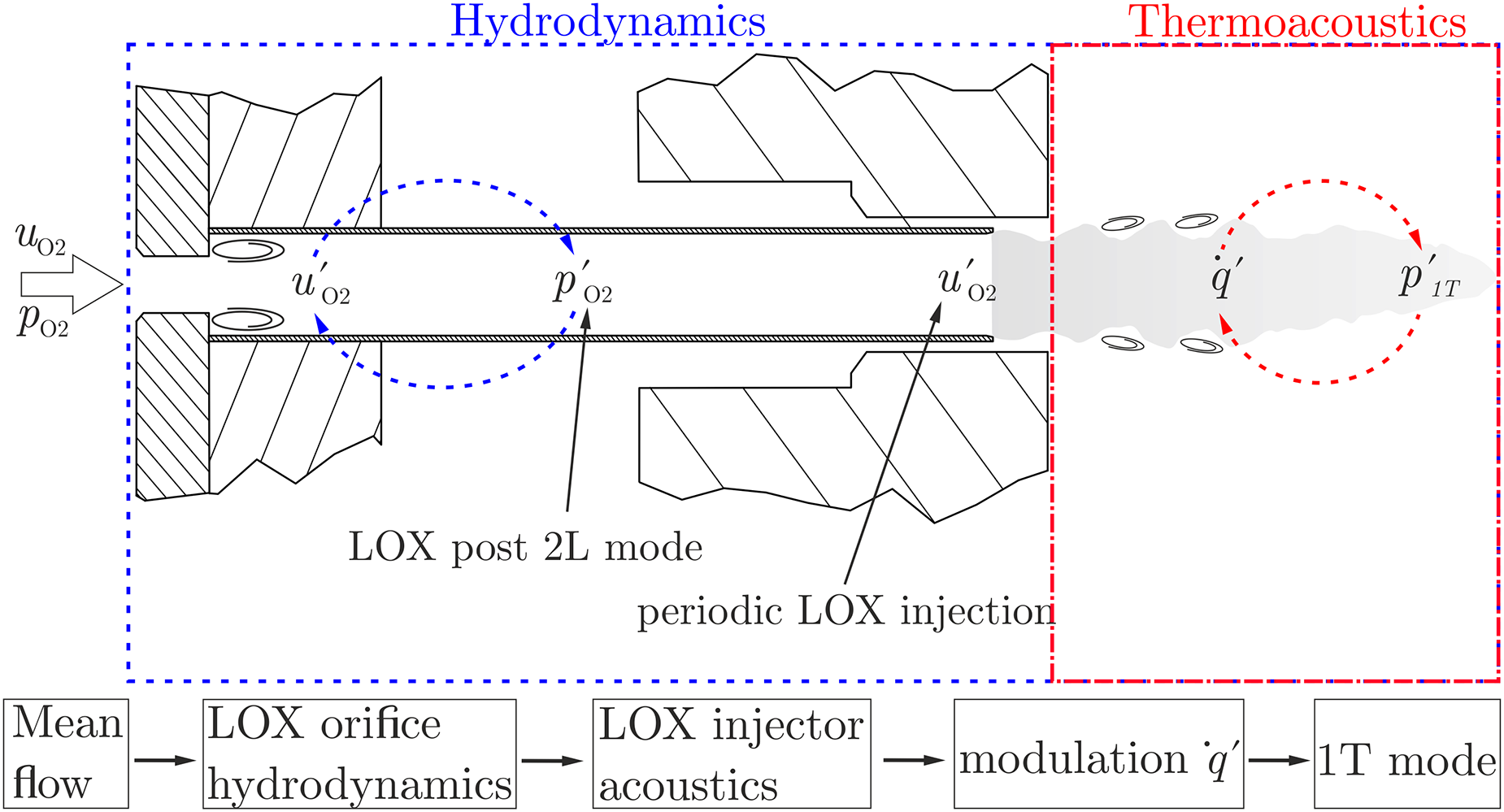
Sketch of the relation between hydrodynamics and thermoacoustics in the excitation of the BKD combustion instability.
Summary and Conclusion
The DLR research combustion chamber BKD shows self-excited combustion instabilities of the 1T mode for certain operating conditions. In previous studies the basic instability excitation mechanism was identified as LOX-injection coupling. This is a rather common instability excitation mechanism for cryogenic rocket engines with shear coaxial injectors. However, so far it was not understood which processes lead to the excitation of the acoustic eigenmodes of the LOX post tubes, which then modulate the injection and heat release rate in the chamber that lead to the combustion instability.
Several LOX post excitation sources which have been described in publications were investigated for BKD in this study. The results of the analysis show that broadband combustion noise, and two-phase flow effects are unlikely to be responsible for the LOX post acoustic excitation. In addition, the unique application of fibre-optical probes to measure OH* oscillations in the recess-volume of the injectors could be used to rule out intermittent flame anchoring as a factor.
Further analysis of the flame dynamics measured in the recess volumes revealed additional dynamic frequency content which was not of acoustic origin. These oscillations correlate with the temporal evolution of the LOX flow velocity in the injection system. For that reason, an internal hydrodynamic excitation source of the LOX-post acoustics was hypothesized. Finally, the required combination of conditions, which lead to an excitation of the chamber 1T mode in this combustor are a close frequency spacing between the acoustic eigenmodes of the LOX injectors and the chamber 1T mode and a Strouhal number, which can lead to a flow-induced excitation of the longitudinal eigenmodes in the LOX injectors.