
Abstract
In traditional ice hockey skates with fixed blade holders, a shorter blade radius allows for greater variation in the foot’s overall pitch angle as the contact point shifts from the rear to the front of the blade. Therefore, a shorter blade radius can help players better adapt their pitch angle to different skating demands as compared to a longer blade radius. However, reducing the blade radius also decreases the ice contact area, and when the contact becomes too limited, plowing resistance increases, creating a trade-off that can negatively impact speed and glide. To address this trade-off between maneuverability and glide resistance, a novel dynamic blade holder incorporating a rocker mechanism has been developed. This study presents a mathematical equilibrium model of the dynamic blade holder to evaluate its effect on skate pitch angle. The model demonstrates how the rocker allows independent adjustment of the pitch angle without altering blade curvature, effectively amplifying pitch changes as a function of contact point displacement. Analytical expressions describe this amplification and its dependence on rocker radius, providing practical tools for understanding and optimizing skate design. Future research should examine the biomechanical implications of this approach in real skating scenarios.
Keywords
Introduction
The geometry of ice hockey skates affects a player’s ability to generate force against the ice during various movements. One key factor in this regard is the angle of the foot relative to the ice, referred to here as the skate pitch angle (θ, as shown in Figure 1). It has been suggested, for instance, that a more forward pitch angle (larger θ) may be advantageous for forward acceleration. In contrast, a more neutral pitch angle (smaller θ) may be preferable for turning and backward movements. 1
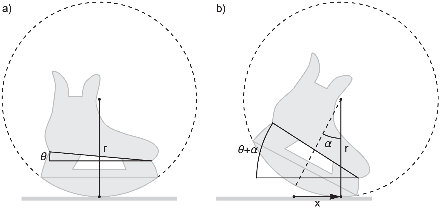
Illustration of a skate with the radius of curvature for the blade, r, and a forward skate pitch angle θ. In (a), the skate is shown in a neutral position, while in (b), it is rotated clockwise by an angle α. The total pitch angle for the foot is then θ + α. To improve the clarity of the model, the radius of curvature (r) has been intentionally illustrated as much smaller than that of actual ice hockey skates. The fixed-radius section of an ice hockey skate blade typically extends over approximately 60% of its length, while the anterior and posterior 20% have a progressively smaller radius of curvature to maintain blade-ice contact even during extreme forward or backward tilts. However, in this model, the entire blade is assigned a fixed radius, representing only the primary functional aspect of skating in less extreme positions.
In addition to θ, the angle of the skate (α in Figure 1), which arises from changes in the contact point (x in Figure 1) between the blade and the ice, also contributes to the overall pitch angle (θ + α). As the skate rotates by an angle α from its neutral position (illustrated on the left in Figure 1), the contact point shifts by a distance (x) determined by the arc length along the blade’s curvature (see equation (1)).

As shown in equation (1), the angle α varies inversely with the radius of curvature (r) for a given displacement (x) of the contact point from the neutral position. Thus, a shorter blade radius of curvature enables a greater change in the overall pitch angle. However, the curvature of the blade influences more than just the pitch angle; it also directly affects the skate’s maneuverability and speed by altering the contact area with the ice.
For a fixed blade width, a larger radius of curvature results in a larger contact area, 2 which may reduce maneuverability and increase resistance due to wet friction. Conversely, a smaller contact area increases the pressure exerted on the ice, increasing the likelihood of deforming or fracturing the ice. Above a given pressure, the resistance will increase as plowing resistance begins to dominate over wet friction.1,2 Therefore, an optimal blade radius of curvature likely exists for each player, balancing maneuverability, speed, and control across various aspects of gameplay. This optimal radius depends on an individual player’s movement patterns and physiological characteristics and can only be estimated through practical experience.
It was concluded in the early 2000s that National Hockey League (NHL) players typically used a single blade radius of curvature between 8 and 12 feet (2.44–3.66 m). 1 Today, players typically select blades with a radius of curvature in a range between 9 and 13 ft. (2.7–4 m).This range of curvature implies that the ability to rotate the skates to change the overall pitch angle becomes limited. As follows from equation (1), moving the contact point from the back to the front of the blade, a distance of not more than 30 cm, on a blade with a radius of curvature of 2.7 m results in less than 0.12 rad (≈7°) of skate rotation, and of course, even less for a longer radius of curvature.
To overcome this limitation and decouple the necessity of maintaining a sufficiently large contact area with the ice from the ability to rotate the skates, a novel dynamic blade holder has been developed by Marsblade Flow Motion Technology AB (Östersund, Sweden). Recent findings from our research group suggest that this new technology significantly enhances skating performance compared to traditional fixed-blade holder designs. 3 Considering the potential benefits of this new design, this study aims to provide a deep understanding of its functioning through analytical modeling of its equilibrium positions.
Methods
A theoretical mathematical model was developed to describe the geometric and mechanical behavior of this type of dynamic blade holder. In this design, the dynamic blade holder features a rocker, shaped as a circular section, positioned between the blade and the shoe (Figure 2).
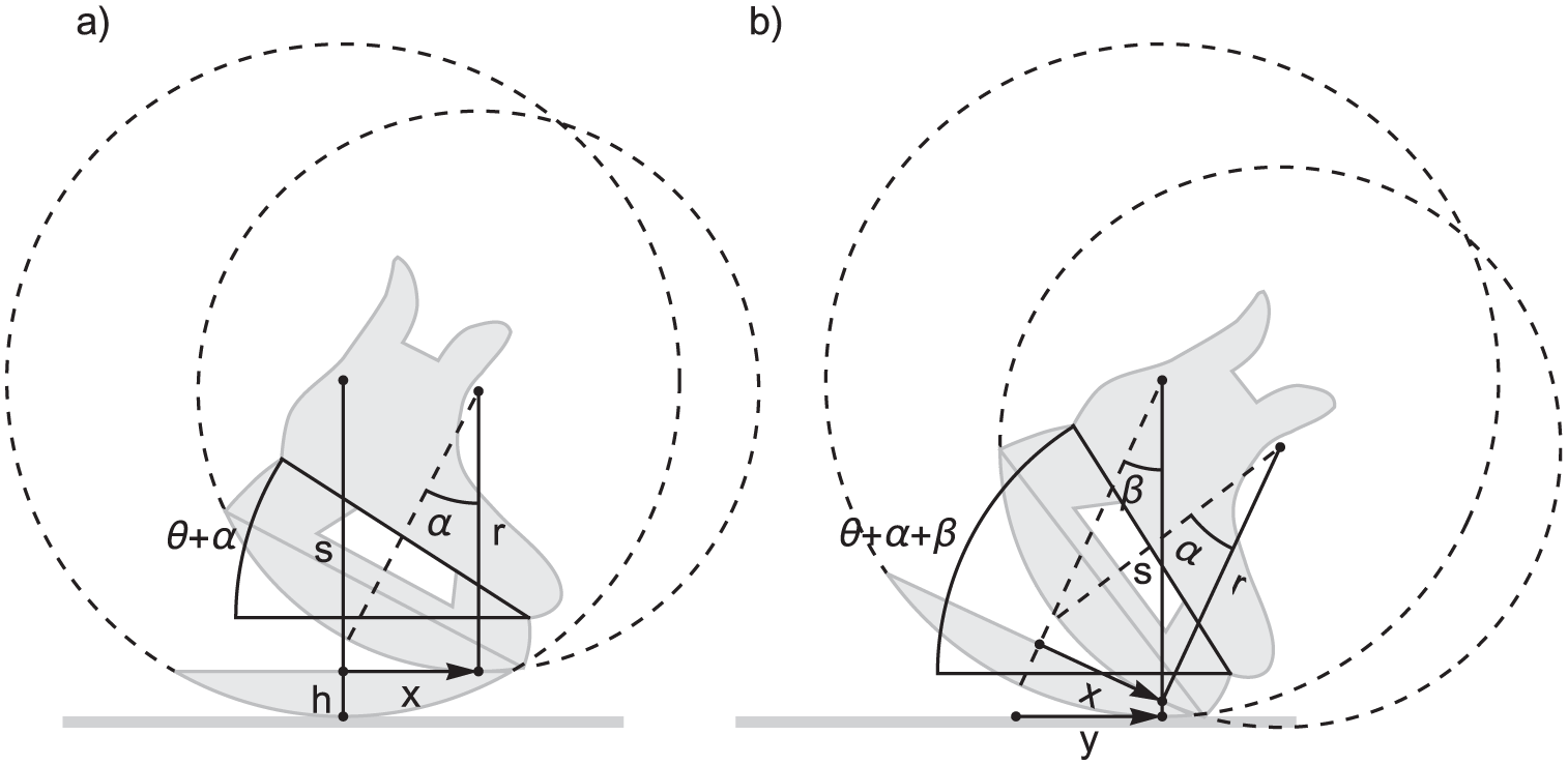
Illustration of a skate with a dynamic blade holder, featuring a rocker mechanism positioned between the shoe and the blade in contact with the ice. The rocker has a radius of curvature r, while the blade has a radius of curvature s. The blade height h is shown here adjusted to fit the arc of the circular sector precisely, but h can be modified by adding additional height above the blade’s circular sector. In panel (a), the rocker is rotated clockwise by an angle α, shifting it to a nonequilibrium position, because the blade remains unrotated. In panel (b), the blade is rotated by an angle β, to its equilibrium position. This rotation causes the blade’s contact point to move forward by a distance y, and the total pitch angle of the foot becomes θ + α + β.
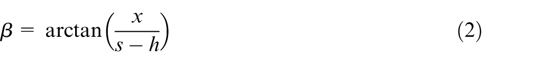
The rocker functions just like the blade in the skate without a dynamic blade holder (Figure 1). However, instead of contacting the ice, it rolls on the straight upper edge of the blade (compare Figure 1(b) with Figure 2(a)). When the rocker is rotated by an angle α, its point of contact with the blade moves a distance x along the upper edge of the blade, as described by equation (1). This displacement causes the blade to become unbalanced, prompting it to rotate to its equilibrium position (Figure 2(b)). In this position, the contact point between the rocker and the blade aligns directly above the contact point between the blade and the ice. Geometrical considerations then give β according to equation (2).
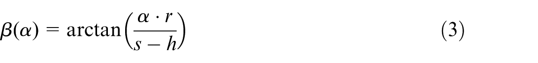
Utilizing equation (1), equation (2) can be restated as equation (3), making the linkage of α and β through the equilibrium condition explicit:
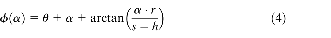
The total pitch angle of the foot (φ = θ + α + β) can then be expressed as a function of α, treating the other parameters as fixed constants.
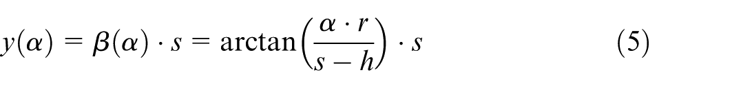
The distance y moved by the contact point on the ice is equal to the arc length rolled along the blade. Utilizing equation (3), y can be expressed as a function of α.
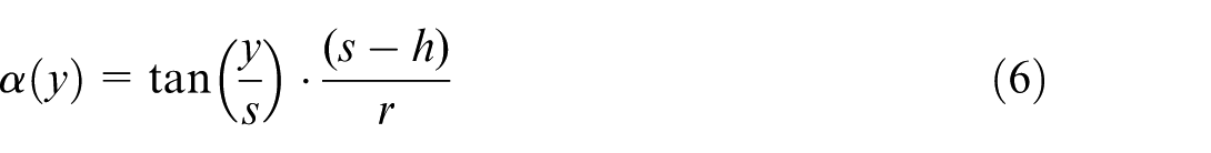
Because varying the contact point between the blade and the ice (y) may provide a more intuitive way to conceptualize interaction with the skate than rotating the rocker by an angle α, we will express α as a function of y by solving equation (5) for α.
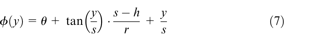
Now, utilizing equations (4)–(6), the total pitch angle of the foot (φ) can be expressed as a function of y.
In a skate with a dynamic blade holder, the radius of curvature of the blade (s) continues to govern the interaction with the ice in the same manner as in a skate without a rocker. Therefore, s must remain within the range of 2.7–4 m, as previously discussed, which implies that the blade’s contribution to the pitch angle (β) will similarly be limited, with maximum values below 0.12 rad.
However, the introduction of the rocker decouples the foot’s total pitch angle from the blade, as the radius of curvature of the rocker (r) determines the amount of foot pitch through the middle term on the right side of equation (7). Notably, this term vanishes as r approaches infinity, leaving the total pitch angle as θ + y/s (with y/s = β, as derived from equation (5)). This limiting case aligns with expectations, as a flat rocker corresponds to a skate without a rocker mechanism, where β in Figure 2 would directly correspond to α in Figure 1.
Moreover, the middle term, containing the tangent of β, becomes nearly linear for small values of β. This near-linearity can be understood from the Maclaurin series expansion of the tangent function:
Replacing the tangent with its linear term and simplifying equation (7) gives,
For a β of 0.12 rad, the linear approximation in equation (9) would result in an error in ϕ of less than one tenth of a degree (this estimate is based on the second term of the Maclaurin series, using the parameters s = 2.7 m, h = 0.03 m, and r = 1 m). Thus, for all practical purposes, equation (9) can be used as a convenient approximation for the exact solution in equation (7).
Results
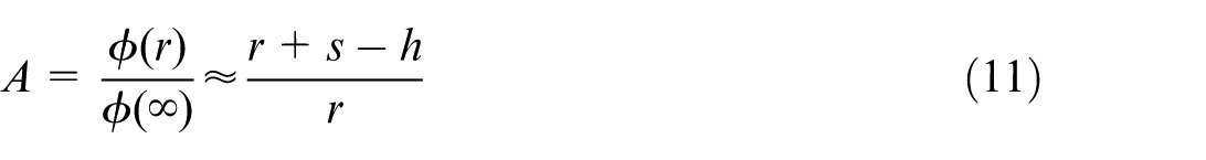
Comparing equations (1) and (9), it follows that a skate with a dynamic blade holder exhibits the same change in pitch angle due to a shift in the contact point with the ice (y) as a conventional skate with an effective blade radius of:
Figure 3 illustrates how the radii of curvature of both the blade and the rocker influence the total pitch angle of the skate (ϕ) as the contact point with the ice (y) shifts along the blade. The radius of curvature of the rocker (r) has a significant impact on the total pitch angle, whereas the radius of curvature of the blade (s), constrained by its limits determined by blade-ice interaction, has only a minor effect.
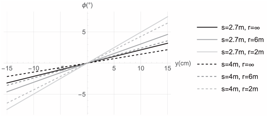
Plot of the total pitch angle of the foot (φ) as a function of the distance to the contact point with the ice along the blade (y), as defined in equation (7), shown for various values of the blade’s radius of curvature (s) and the rockers radius of curvature (r). In all instances, the skate pitch angle (θ) has been set to zero. Because θ simply adds a constant to φ, any nonzero value would just translate the curves a distance θ in the vertical direction. In all cases the height of the blade (h) has been set to 3 cm.
The rocker can be considered as an amplifier of the pitch angle resulting from the movement of the point of contact with the ice (change of y). The amplification factor (A), which quantifies this effect, can be determined from equation (7) for a given radius of curvature of the rocker (r), while a simplified linear approximation can be obtained using equation (9).
Discussion
This study demonstrates that the rocker in the dynamic blade holder allows for greater variation in the pitch angle of the skate, as compared to conventional fixed blade holders, without affecting the blade-ice interaction. As shown in equation (11) and visualized in Figures 3 and 4, the amplification factor (A) increases as the rocker’s radius of curvature decreases. Importantly, this increased amplification allows for enhanced control over pitch angle while maintaining sufficient blade-ice contact, a key limitation in conventional skate designs. The mathematical model provides a framework for quantifying this amplification and offers practical insights for optimizing rocker geometry to match specific performance demands.
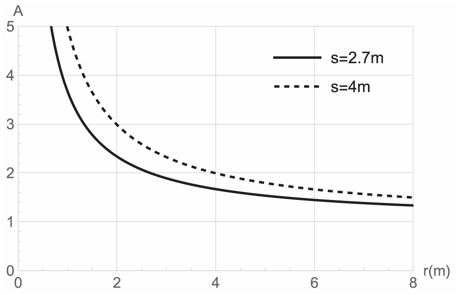
The amplification factor (A) of the foot pitch angle due to changes in y is plotted as a function of the rocker radius of curvature (r), for blade radii of 2.7 m (solid line) and 4 m (dotted line). The blade height (h) is set to 3 cm. As r increases, the function asymptotically approaches A = 1, and as r decreases toward 0, A grows infinitely.
Some blades and rockers exhibit a variable curvature along their length. In such cases, the current model can be applied to separate sections with distinct geometric parameters. For example, a blade with a fixed radius of 2.7 m, combined with a rocker featuring a 2 m radius in the back half and no curvature in the front half, would be represented in Figure 3 such that the back section (left of the origin) corresponds to the lightest solid line, while the front section (right of the origin) corresponds to the solid black line.
Although this sectional modeling approach allows the framework to accommodate blades with varying curvature, it does not directly account for continuously changing profiles such as elliptical blade shapes. However, as demonstrated in Figure 3, the impact of blade curvature variation within the range of 2.7–4.0 m on the pitch angle is relatively small compared to the dominant effect of the rocker curvature. Thus, a simplified model using an average blade radius offers a reasonable approximation for many practical purposes.
Future work could explore the biomechanical implications of these variations, examining how different rocker and blade geometries influence skater stability, agility, and energy efficiency.
Conclusions
The developed mathematical model shows that a dynamic blade holder with an integrated rocker mechanism can substantially increase the pitch angle range without compromising blade-ice interaction. The enhanced control over pitch angle arises from a tunable amplification effect governed by the rocker’s radius of curvature. The model provides a valuable analytical tool for optimizing skate design and serves as a foundation for further experimental and biomechanical investigations.
Footnotes
Ethical considerations
Not applicable.
Consent to participate
Not applicable.
Consent for publication
Not applicable.
Funding
The authors received no financial support for the research, authorship, and/or publication of this article.
Declaration of conflicting interests
The authors declared no potential conflicts of interest with respect to the research, authorship, and/or publication of this article.