
Abstract
This paper presents a low-cost, portable, multi-view table tennis umpiring framework, as a viable alternative to the current expensive systems which are almost exclusively restricted to elite professional sports. Table tennis has been selected as the sport to evaluate this framework primarily because it comprises many different complex match elements, including the service, return and rally elements, which are governed by a strict set of regulations which need to be umpired. The aim is to develop novel methods to analyse and judge the legality of such key match facets, with ball detection and tracking in video frames being integral to reliably and accurately determining the ball’s position and flight path during rallies. While a low-cost option is attractive and offers several benefits, it is a technically challenging problem due to the small number and generally low-resolution cameras that are used. A novel multi-view camera setup and multi-agent system (MAS) framework is presented, which comprises computationally lightweight agents which detect and track the table tennis ball, create a 3D representation of the flight path of the ball, predict the ball’s trajectory, and identify and analyse key facets in a table tennis rally. The MAS correctly detects all state transitions in seven test table tennis sequences with minimal latency and while the processing rate of a standard computer may be unable to analyse long rallies in real time, the potential of running the MAS on a parallel architecture is a propitious alternative. The MAS is also scalable, enabling additional camera pairs to be deployed to achieve enhanced accuracy and coverage. The framework affords the potential to reform the way matches are umpired, especially for amateur players, providing an economic and objective manner of dispute resolution, while the multi-view facility is extendible to other relevant ball-based sports. The ball flight path analysis mechanism can be exploited as a valuable training tool for skill development.
Keywords
Introduction
Background
In recent times, the role of computer vision in identifying and understanding events happening in digital images and videos has grown dramatically. Due to its rich potential in many different areas, computer vision has been utilised in pattern recognition, medical imaging, security surveillance, three-dimensional (3D) reconstruction and robotic applications. The development of computer vision has made it feasible to detect and track target objects, with many sports increasingly considering this technology for verification purposes in key umpiring decisions. One of the main controversies surrounding contemporary sports competitions are incorrect decisions made by match officials. 1
To assist human umpires in making more accurate decisions, there has been a growing trend to employ vision-based systems for reviewing problematic officiating decisions at a range of professional sporting events such as the Wimbledon Tennis Championships and English Premier League football matches. Likewise, researchers are exploring computer vision technologies to develop game highlight detection algorithms and virtual replay systems. Examples include determining whether a target object is inside or outside of the playing area such as Hawkeye, 2 the close-up view of a player after a goal 3 or showing the trajectory of the ball on a virtual court by rendering the graphics of the ball’s motion. 4 This technology not only supports human umpires but provides proof of their decision-making and reduces the likelihood of mistakes.
Despite offering significant advantages, existing systems2–4 have struggled to meet ever-growing demands in terms of high deployment costs, complex installation and limited functionality. Moreover, automatic umpiring of an entire match in a real match setting has not been achieved, which provided the motivation behind this project. Furthermore, existing systems2–4 are too expensive and inflexible for lower-tier, amateur sporting communities to embrace, so a cost-effective, easy-to-operate automated umpiring system is a very desirable objective.
Table tennis umpiring
Table tennis is an Olympic sport with millions of players worldwide. It is governed by the International Table Tennis Federation (ITTF) and the official rules are specified in the ITTF handbook. 5 It has many complex match elements, including the service, returns, rallies and faults. The ball travels at high speed and its view can be occluded by the players and other match objects. These factors collectively make umpiring difficult even for a well-trained human official and it is this context that makes table tennis an excellent sport for testing and challenging an automatic umpiring system.
To develop an effective, low-cost automatic umpiring system presents several key technical challenges to overcome, including:
Accurately tracking a table tennis ball is a difficult task due to its small size and background complexity of match scenes.
The ball often travels at high speed. 6 The effect on the captured image of the ball is shape distortion, allied with object blurring and colour deviation caused by light-level changes between frames in fast sequences, and occlusion by the players or their rackets.
While a low-cost option has benefits, it is technically more challenging due to limited hardware and generally low video resolutions used.
Umpiring a complete rally is a very complex task and requires many concomitant decisions, so the demand for timely and accurate observations of rallies imposed by the table tennis rules is exacting. To fulfil these requirements, the processing analysis must be expedited and consistently reliable judgements rapidly generated.
Some match elements are very difficult to judge. For example, whether the ball touches the net, hits the edge of the playing surface (legal), or the other side of the table edge (a foul). These kinds of judgements are problematic even for professionally trained umpires. 7
Determining a fault in a rally is also difficult because there are many different fault categories such as double bouncing, a return not bouncing on the correct side of the table, and the ball hitting the floor.
This research is motivated by the availability of advanced computer vision technologies and artificial intelligence (AI) tools, which can aid in developing algorithms more efficiently. Exploring these useful technologies and developing a strategic methodology to effectively identify the state of a rally for match umpiring were the main motivations behind this research. The aim is to develop a framework that can be used for automatic umpiring in ball-based sports, using table tennis as the testing ground. The focus is on developing techniques and implementing algorithms rather than building a complete system. To make the system accessible to amateur players, the system is aimed to be low-cost, portable, and straightforward to both calibrate and install.
In the next section, relevant literature on object tracking and umpiring tools are reviewed, while the proposed multi-view ball tracking system is explained in the section entitled Multi-view ball tracking system. Experimental test results are critically evaluated in the section named Experimental results, while the future work and some concluding remarks are made in the Constraints and future work and Conclusion sections respectively.
Literature review
While there is a large corpus of work on object tracking techniques that produce satisfactory results, they are generally both object and application-specific, therefore this literature survey will focus on tracking a table tennis ball. Two previous studies for ball tracking for umpiring purposes have been proposed by Wong and Dooley 7 and Byrd. 8 The two-pass colour thresholding (CT) technique 7 identified the ball from real match scenes, and while satisfactory results were achieved, it only covered the service component of a rally during which the ball does not travel at high speed. In contrast, the automated scoring system proposed by Byrd 8 tracks the table tennis ball in real-time and relates to the table and net to determine when a point is scored. However, the setting for Byrd’s work is an artificial laboratory environment where the ball is painted neon green against a uniformly black background. Such a contrived environment significantly reduces the ball detection challenge, but it contravenes the laws applicable to table tennis tournaments which mandate the ball colour can only be matte white or orange. 9 Other table tennis balls tracking studies10–14 have focused on robots playing table tennis. The sampled points method proposed by Zhang et al. 10 aimed to recover pixels unintentionally lost during the adjacent frame differencing process. Although experimental results revealed promising ball detection performance, background pixels were sometimes incorrectly classified as belonging to the ball, which degraded the overall detection accuracy. In contrast, Liu et al. 11 attempted to improve the tracking performance by employing an iterative dynamic window tracking method. Despite the system being able to consistently track the ball, the resulting computational time complexity incurred was mitigated against real-time operation. An alternative approach to ball tracking involved a multi-view scheme with an aerodynamic model of the ball’s 3D flight path, 12 which has been improved by Bao et al. 13 by means of a bouncing model, which took into consideration the bouncing characteristic of the ball. While some degree of improvement in the tracking of a table tennis ball was achieved, the test video sequences used comprised relatively simple backgrounds, which were not typical of real match scenes, where the view can become occluded by the players against complex backgrounds where ball merging can occur. Moreover, in the dual-camera based 3D trajectory reconstruction algorithm, it was critical that both cameras detected the ball at the same time to reliably calculate the 3D position of the ball. This constraint means the 3D position of the ball cannot be determined when one of the cameras fails to detect the ball. In addition, a vision system using multiple cameras must simultaneously process frames from different views, thus incurring a heavy overhead which impacts the system’s performance. Machine learning has also been considered for table tennis ball tracking. 14 Instead of using a physical model to predict the ball trajectory for a playing robot, artificial neural networks (ANNs) were trained using 200 real-world trajectories as training data. The ANN trajectory predictor produced a mean error of 39.6 mm, which is analogous to the diameter of a table tennis ball, and while this level of error is acceptable for applications such as playing robots, it is not sufficiently accurate for umpiring purposes.
In summary, no existing solution addresses the challenges of ball tracking in a full match rally, which is an essential requirement in the context of an automatic umpiring system. Furthermore, current solutions are heavily reliant on the availability of aerial views of the scene, which renders the ball against a generally simple background that is, a uniform-coloured table and floor.10–14 Obtaining aerial views is not always feasible as most table tennis tournaments take place at multi-purpose sport venues and fixing cameras to the ceiling or high wall is not practical. To address this significant gamut of challenges, this paper investigates the development of a novel portable multi-view ball tracking system design using multiple agents that can accurately manage difficult and diverse ball detection scenarios in real match scenes.
Multi-view ball tracking system
A multi-view ball tracking system has been developed as the testbed for the automatic umpiring framework. This section discusses the setup of the experiment environment, the ball detection and tracking algorithms, the table tennis rally analysing method and the multi-agent system adopted for automating the umpiring of rallies.
With the aim of developing a cost-effective system, the video cameras chosen needed to be low-cost but able to capture video at high enough frame rate and of sufficient resolution and clarity. A preliminary study showed that the ball can be detected from videos of table tennis rallies captured at 300 frames per second (fps) and of a resolution of 512 × 384 pixels. 7 The Casio EX-F1 digital camera (Casio Computer Co., Ltd, Tokyo, Japan) was thus chosen based on these requirements. To balance between cost and available views, four cameras were employed to provide either four single views or two stereo views of the court where the table tennis table is located (table has the dimensions of 12 m × 6 m).
Camera placement and calibration
Tracking a table tennis ball in a real match scene is challenging because the ball is small, fast moving and its view can be obscured. The image of the ball can also become distorted or darkened if the video is captured with inappropriate aperture size and shutter speed, and the range of these parameters is limited by the camera specifications. Environmental factors such as uneven illumination, confusing background objects, spectators’ movements and reflective table surface further compound the ball detection process. Figure 1 shows some examples of the ball in these challenging detection situations.
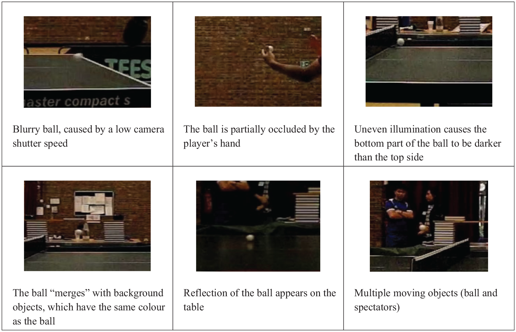
Example images of the ball in challenging detection situations.
A further limitation is that table tennis tournaments usually take place in multi-purpose halls preventing the installation of aerial-view cameras. To address these challenges, the ball tracking system should be able to monitor the ball using multiple cameras so that when the ball is undetectable in one view, it can still be reliably detected in another. To achieve this goal, a novel multi-view camera arrangement is presented, which is illustrated in Figure 2. The system comprises four high speed cameras positioned at the first and third quarter length along the table length. Each camera monitors two thirds the length of the table, rather than the entire table because this configuration allows the cameras to be placed relatively close to the table to obtain a better view. Each camera has both an opposite facing and adjacent partner, for example, Cam 2 and Cam 3 are opposite and adjacent to Cam 1 respectively. The opposite facing cameras work together to tackle the occlusion problem, while the side pair monitors the whole length of the table together, with the views overlap at the middle, where the net is located.
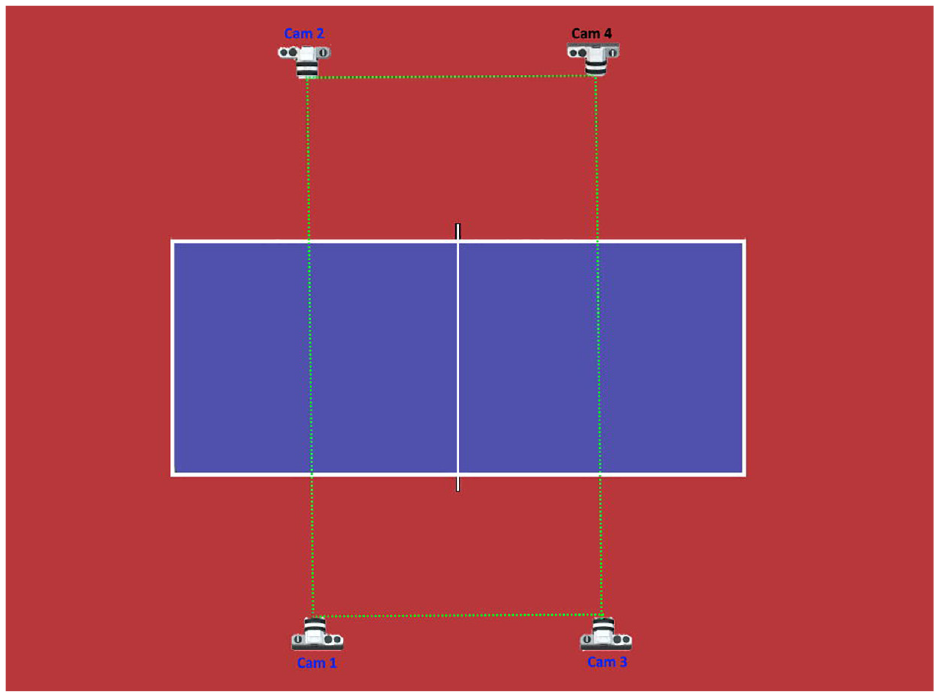
Multi-view cameras configuration.
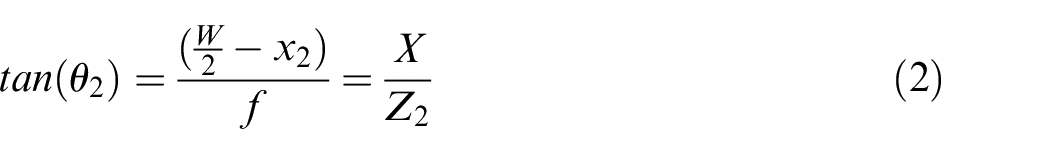
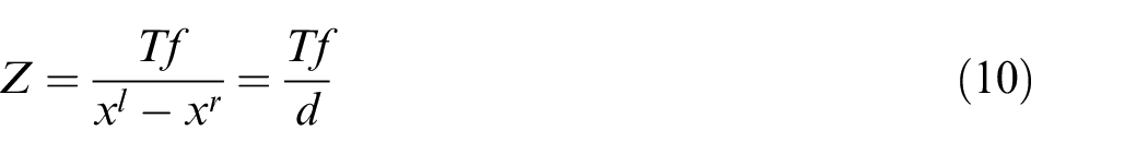
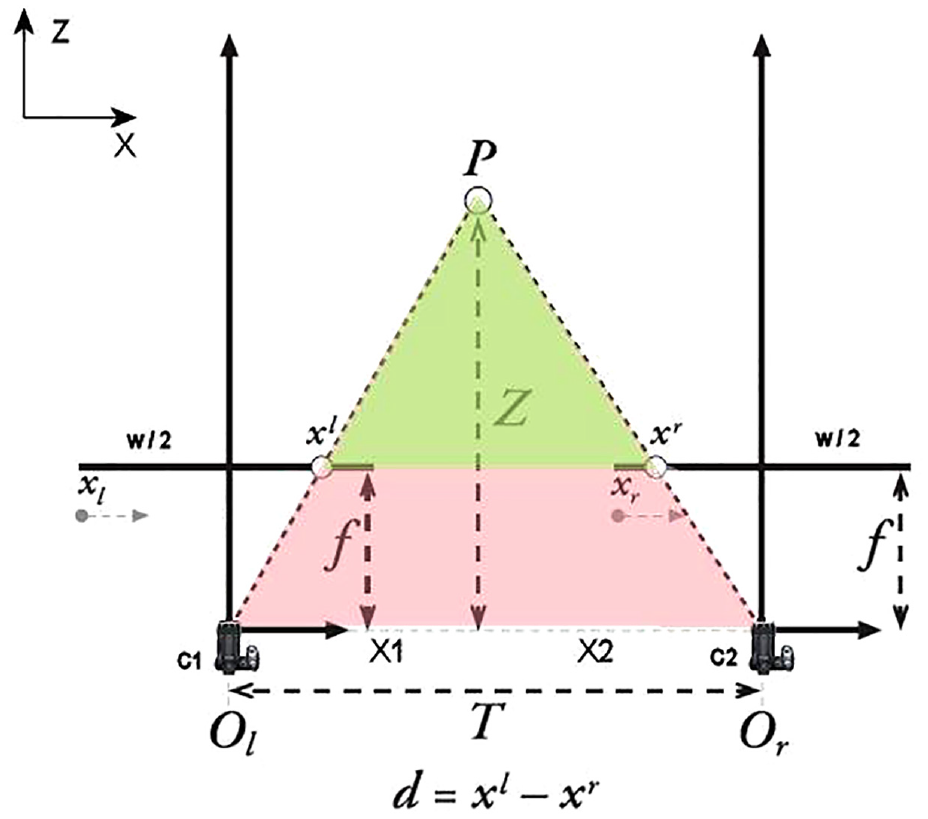
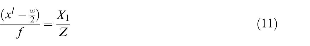
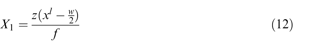
To track the ball for umpiring purposes, the 3D real-world coordinates of the object must be derived from the two-dimensional (2D) images captured by the cameras. This particular camera arrangement affords two options for deriving the 3D ball position. When the ball is in a position where the pair of opposite facing cameras can view it, the ball coordinates are calculated using the image positions of the ball detected by this pair. Figure 3 shows the aerial view of an opposite facing camera pair, which allows the X- and Z- coordinates to be calculated.
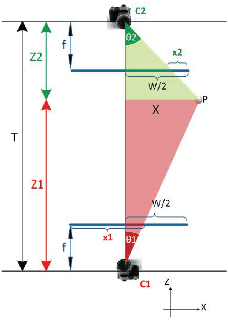
Aerial view of the opposite facing camera pair.
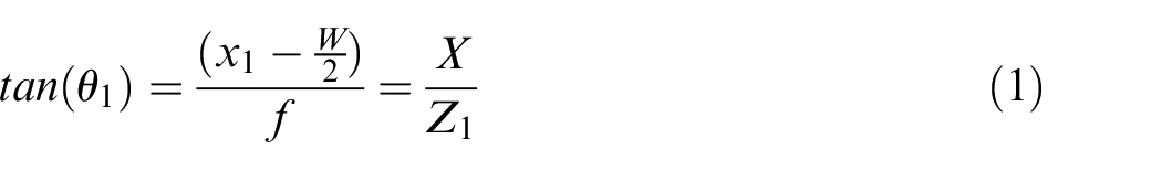
Let the principal point of Cam 1 (C1) be the origin. The X- and Z-coordinates can be calculated using the following relationships:

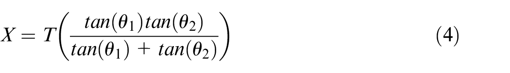
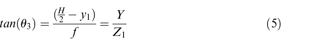
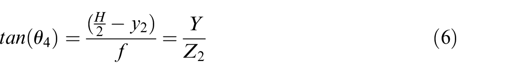
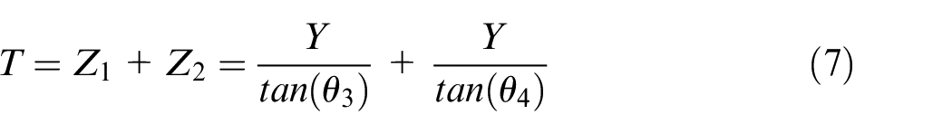
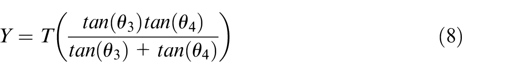
As the Y-coordinate is not visible in the aerial view, the side view of the camera configuration (Y against Z axes) was drawn and shown in Figure 4.
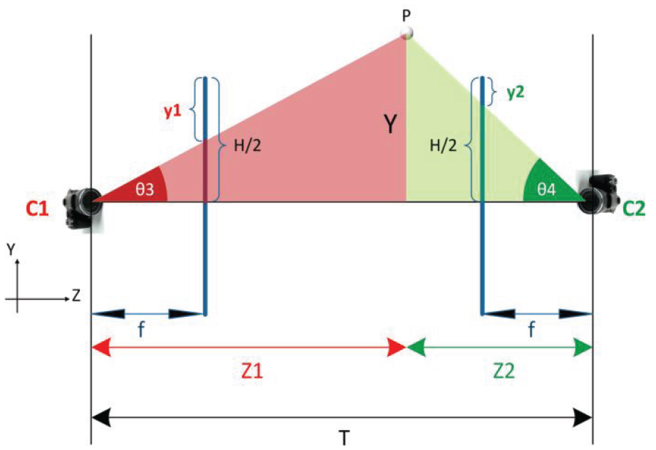
Side view of the opposite facing camera pair.
The Y-coordinate can then be calculated using:
However, if the ball cannot be detected by one of the cameras in the pair, the other camera in the pair can attempt to work with its side partner to derive the real-world coordinate using the geometry calculation, as shown in Figure 5 (aerial view). Based on similar triangles, the Z-coordinates are then calculated by:
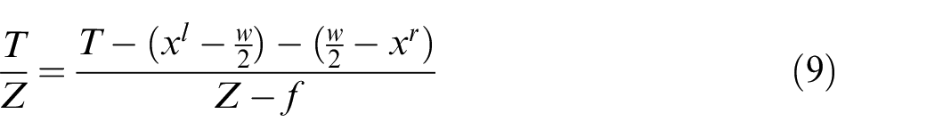
Aerial view of the side-by-side camera pair.
and the X-coordinate is determined from:
The Y-coordinate can be calculated by looking at the side view (Y against Z axis) of the cameras, as shown in Figure 6, and applying equations (13) and (14).
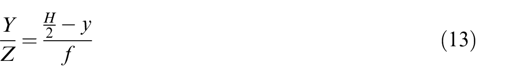
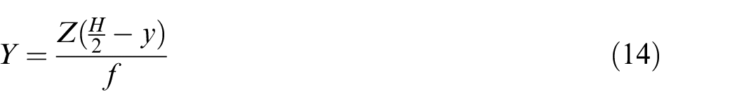
Side view of the side-by-side camera pair.
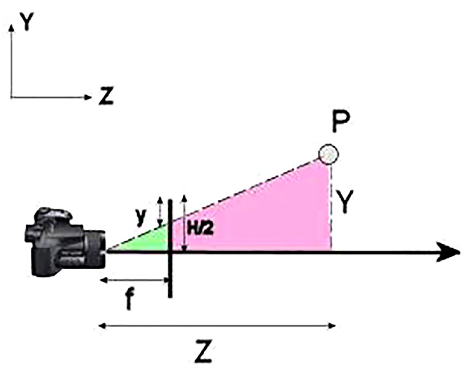
To determine the accuracy of the detection system, a set of reference points, known as the real-world object coordinates, were used as the ground-truth for comparative evaluation. The ground truth was constructed by carefully calibrating a double-sided checkerboard at various marked locations on the table during filming, as shown in Figure 7. The checkerboard had four rows and five columns of identical sized black squares distributed evenly upon a white board, so the position of each corner is known a priori. The distance between the checkerboard and the principal point of Cam 1 (used as the origin) was carefully calibrated at each marked location, so the 3D coordinates of all corners of the checkerboard were calculated. Apart from the checkerboard corners, both the table corners, and tips of the net poles at both sides were used to synthesise the ground truth, which comprised a total of 288 reference points.
An upright double-sided checkerboard was used for creating reference points.
A verification test was performed by manually identifying the image positions of the reference points in the images captured by the opposite facing cameras pair and calculating their 3D coordinates using equations (1) through (8). The results revealed that the average Euclidean distance between the 3D coordinates of the measured reference points and those calculated by the system was 4.8 cm, which is larger than the diameter of the ball and this difference is too high for the proposed umpiring purpose. The Euclidean distances varied non-linearly with respect to the distance between the reference points and origin. This discrepancy was mainly due to the misalignment between the opposite facing and side-by-side cameras, measuring error, and inaccurate image positions of the reference points. As each camera has up to six degrees of freedom (X-, Y-, Z-translation, pitch, roll and yaw), it is very difficult to achieve perfect alignment, while the spatial resolution of these cameras is also low (512 × 384 pixels). To reduce this discrepancy, a corrective error compensation model was constructed that takes the calculated coordinate to generate an estimated error vector (

where
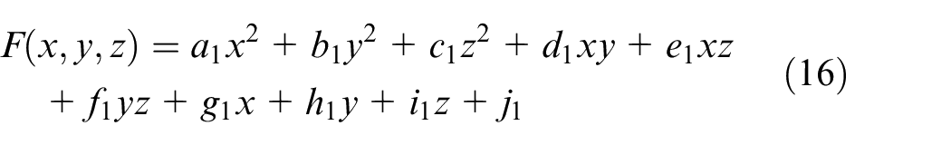
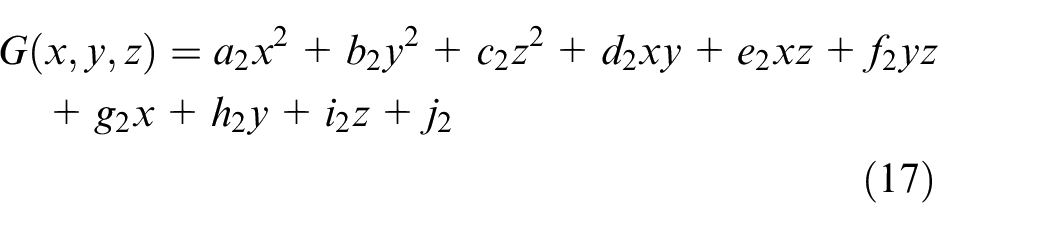
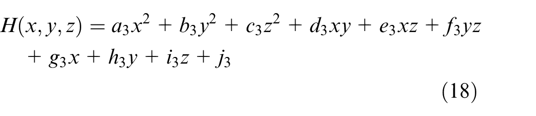
Because the error is non-linear, F(x,y,z), G(x,y,z), H(x,y,z) were defined as quadratic surfaces, as shown in equations (16) through (18) where an, bn, cn, dn, en, fn, gn, hn, in, and jn are coefficients of the surfaces, for n = 1, 2 and 3.
To determine the coefficients for the quadratic surfaces, the multivariate polynomial regression 15 was used. To prevent overfitting, a small subset of 32 reference points was randomly selected from the ground truth as training data, with 45 ‘unseen’ points chosen for validation. Figure 8(a) shows the 45 uncorrected calculated (red) and expected (blue) coordinates of the reference points, while Figure 8(b) shows the corrected coordinates of the reference points after error compensation. It is evident the calculated and expected positions are much closer. When the error compensation model was tested on the full dataset, the average Euclidean distance was 0.1 cm, compared with 4.8 cm when the model was not applied, which represents a significant improvement in accuracy.
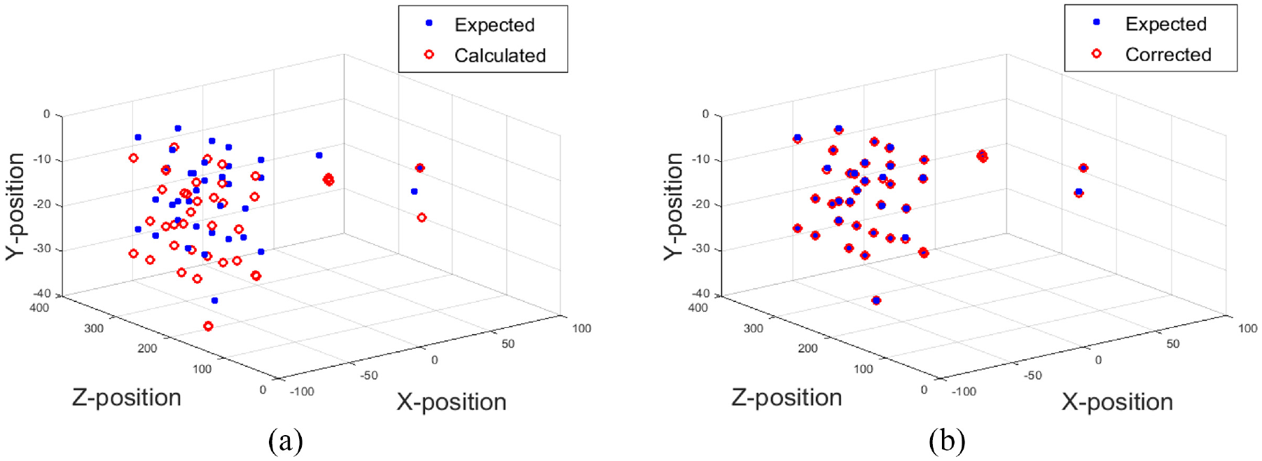
Expected and calculated 3D coordinates of the reference points: (a) uncorrected expected and calculated reference points and (b) corrected expected and calculated reference points.
Using this novel camera arrangement, a large area can be covered by relatively few cameras, though one drawback is the detected image position of the ball from each camera is needed before the 3D ball coordinates can be computed. This requirement means each camera must inform either the other cameras or a central server of its detected ball position. Furthermore, as each camera only monitors two thirds of the table length, it needs to efficiently work with its side partner to monitor the whole table. A restriction of this camera arrangement arises when the ball is at or near the vertical plane that joins the principal points of the two opposite facing cameras, the 3D coordinates of the ball cannot be derived because when θ1 = 0° in equation (1), Z becomes infinite. When this situation occurs, the 3D ball coordinates must be derived using the juxtaposed camera pair. To address this shortcoming, a multi-agent system (MAS) was designed to control and manage the data flow, with a detailed discussion on the Multi-agent system sub-section.
Ball detection algorithm
To resolve these challenges, a ball detecting method was developed using a combination of segmentation, feature-based detection, and motion modelling as explained by Myint et al.16,17 A precis of the detection method is now presented in Figure 9, conceptualising the main constituent elements.
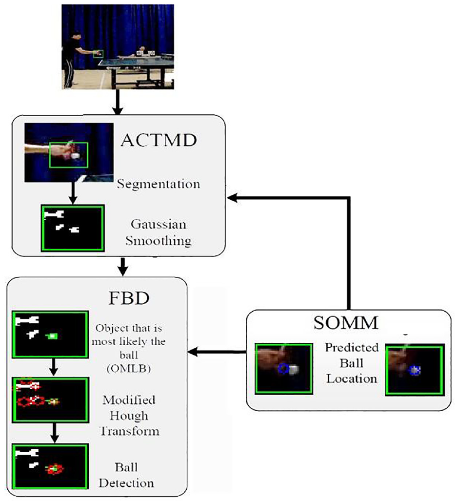
Ball detection algorithm.
Second-order motion model (SOMM)
The ball detection algorithm predicts the ball location and uses this information to guide the ball detection. The predicted ball position is calculated based on the SOMM, by:
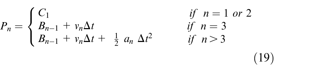
where
While this model is generally reliable, the predicted position can be ambiguous if the detected position was incorrect in the previous frame(s). To avoid error propagation, the predicted position is corrected if its value is significantly different from the centre of the object deemed the most likely the ball. This technique is explained in more depth in the Feature based detection sub-section.
Segmentation
An adaptive colour thresholding and motion detection (ACTMD) method has been developed to segment objects within the region of interest (ROI) where the ball is predicted, with the square area of the ROI maintained as twice the diameter of the ball to minimise the computational cost. If the ball is not detected within a frame, the ROI is then enlarged to increase the probability of ball detection.
ACTMD firstly attempts to segment the ball using the background subtraction technique, but if a ball is undetected (i.e. no moving object appears within the frame), it attempts segmentation using the colour thresholding method. Once a ball is detected, the colour value of the detected ball is used to update the threshold value to improve the colour thresholding performance.
Given the complexity of a match scene, multiple objects are often segmented by ACTMD because it is likely multiple objects are moving or have a similar colour in the ROI. To determine which object is the ball, each is evaluated using features of the ball, such as colour, predicted position of the ball centre, and diameter.
Feature based detection
After segmentation, the Feature Based Detection (FBD) algorithm determines which segmented object is most likely the ball (OMLB) by checking for both the object nearest the predicted ball position and whether its contour encloses the predicted ball position. The object that fulfils both criteria is labelled the OMLB.
FBD subsequently determines the ball centre and radius by finding a circle that best fits the contour of OMLB and is nearest to the predicted ball position. A modified Hough transform algorithm is used to generate a set of circles that fit fully or partially to the OMLB contour, and the circle with the smallest Euclidean distance from the predicted ball position and whose radius matches the expected value is designated as the detected ball.
If only one object is segmented and there is a significant distance variation from the predicted ball position, this result can indicate an unreliable predicted ball position. The segmented object is then deemed to be the OMLB, and the predicted ball position is updated using the centre value of the OMLB.
Rally analysis
A table tennis rally starts from the instant a player serves the ball and ends when a fault occurs. In simple terms, a rally consists of a service and a play component. During the service, the player needs to firstly place the ball on their fully opened and stationary palm, then project the ball upward vertically for at least 16 cm and the server can only strike the ball when the ball is falling; then the ball needs to bounce on the serving player’s court once, cross over the net and bounce on the receiver’s court. The receiver needs to return the ball to the server’s court before the ball touches their own court again. The play will continue until a fault occurs, which is when the above conditions are not met, for example, the ball bounces on one player’s court twice or does not reach the opponent’s court. The full laws of table tennis can be found in the International Table Tennis Federation’s Law of Table Tennis. 9
To automatically umpire a table tennis rally, a state-machine has been designed comprising 14 possible states covering a typical rally, namely:
State 1: Ball on palm
State 2: Ball leaves palm and rises up
State 3: Ball reaches its peak
State 4: Ball is falling
State 5: Ball is initially struck by the server
State 6: Ball initially bounces on the server side
State 7: Ball crosses over the net (server to receiver)
State 8: Ball bounces on the receiver court
State 9: Ball is struck by the receiver
State 10: Ball crosses over the net (receiver to server)
State 11: Ball bounces on the server side
State 12: Ball is struck by the server
State 13: Ball touches the net
State 14: Net ball
During a rally, the states can transit in a variety of ways. Figure 10 illustrates the possible state transitions during a legal rally, with the numbered blue circles indicating different states, and the red circles representing fault states.

States of a table tennis rally.
Multi-agent system
To enable table tennis rallies to be analysed automatically, a MAS was designed to manage and control the data flow, comprising five different agents. A schematic diagram showing their relationship is displayed in Figure 11. Each agent performs a specialist task and because the MAS has a parallel architecture, the workload can be intelligently distributed to a network of computers such that the overall system performance and reliability is enhanced. The respective roles of the five virtual agents are explained in detail in the following 5 sub-sections.
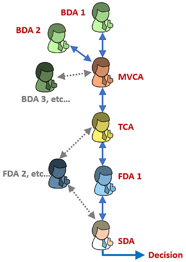
Relationships between various agents.
Ball detection agent
The Ball Detection Agent (BDA) has responsibility for detecting and tracking the ball allied with determining the 3D ball position from the images captured by the camera pairs under its control. It detects the 2D screen position of the ball from each camera and then derives the 3D ball position which is transmitted to the Multi-View Correction Agent (MVCA). For a four-camera system, two BDAs are therefore needed. The BDA also provides supplementary information such as the current frame number, ball radius, and the detection confidence value to the MVCA agent for further analysis. As the MAS is designed to be scalable, it can support multiple BDAs, so if another pair of cameras are available, the system can be readily extended.
Multi-view correction agent
The Multi-View Correction Agent (MVCA) controls the BDAs by requesting or sending information and commands to them. At the start of each rally, the MVCA instructs all BDAs to report the ball position they have detected. If the ball is visible in a BDA’s view, it returns the ball position. Otherwise, it reports ‘No Ball’ and hibernates. Because the MVCA maintains successive ball positions, it can predict the trajectory of the ball for each BDA, so the MVCA can monitor the consistency of the ball’s 3D position between multiple BDAs and estimate the most likely ball position. When the MVCA receives ball positions from a BDA, it compares the reported position with its predicted ball position. If the difference is greater than the acceptable error, the MVCA will recognise that an incorrect ball location is given by a camera. For this scenario, the MVCA can estimate what the ball position would be and forwards this ball position to the BDA that manages that camera view for correction. After the correction, the MVCA sends the ball positions from all BDAs to the TCA.
Trajectory construction agent
When the Trajectory Construction Agent (TCA) receives the ball position from the BDAs via the MVCA, it constructs the complete trajectory of the ball across the whole table, as one BDA only monitors two-thirds of the length of the table. If the ball is in an overlapping area between two BDAs, the TCA will receive ball positions from two BDAs which are monitoring the same area at the same time. If the ball positions between the two BDAs are not in agreement, the TCA chooses the ball position of the BDA based on their historical detection performance. In case a BDA cannot detect the ball for any reason, the TCA can provide the approximate 3D ball location based on a priori knowledge of previous successful detections. To prevent any misalignment errors occurring while the ball is crossing from one visible region to another, the TCA smooths the whole trajectory using a running average error before sending the results to the FDA for further analysis.
Feature detection agent
The Feature Detection Agent (FDA) detects triggers for changing from one state to another. It analyses the X, Y, and Z components of the ball’s 3D trajectory. It considers, for example, whether the horizontal displacement (X) or vertical height (Y) or the depth (Z) are increasing or decreasing, and whether there is a sudden change of velocity, acceleration, or the direction of travel. This analysis of changes means the FDA can detect when the ball gets struck (sudden change of acceleration), bounces on the table (the Y component change direction), crosses over the net (X passes the net position and Y is higher than the net height) or touches the net (X is at net position and Y is smaller the height of the net). To evaluate the correct ball height during the service phase of a rally, the FDA also checks the height of the ball rise and whether the ball is struck above the table. Moreover, the FDA analyses whether the ball is travelling within or outside of the playing surface. As a result, the FDA can provide the SDA with what, where and when events occur.
State detection agent
The State Detection Agent (SDA) manages the state machine for table tennis rallies. It keeps track of the state of a table tennis rally and updates the state based on the information provided by the FDA and the previous state of the rally, as discussed in the Feature detection agent section. The SDA also checks and decides when a fault occurs and identifies the fault type. For example, if the current state is 4 Fall (the ball is falling during service), and the FDA informs the SDA the ball has been struck and the direction of travel is from the server to the receiver. This communication will trigger the SDA to change the current state to 5 Server Strike, as shown in Figure 10.
Experimental results
The MAS was built using the Java Agent DEvelopment Framework (JADE), which complies with the de facto standard set by the Foundation for Intelligent Physical Agents (FIPA). It was chosen because it is an open-source, platform-independent and widely used agent framework. 18 The detection algorithm was written in C++ and adopted the Open Computer Vision (OpenCV) library because C++ codes are very efficient and OpenCV provides a comprehensive set of image-processing functions. An inter-process communication mechanism, Pipe, was used to connect the C++ and Java programmes together. All experiments were conducted on a computer with an Intel® Core™ i7 CPU @ 2.80 GHz.
To critically evaluate the performance of the MAS umpiring system, seven real match test video sequences were applied, each of which covered a range of state transitions and fault conditions occurring during rallies. Table 1 summarises the varying characteristics and rally ending conditions which governed each sequence.
Characteristics of test sequences.
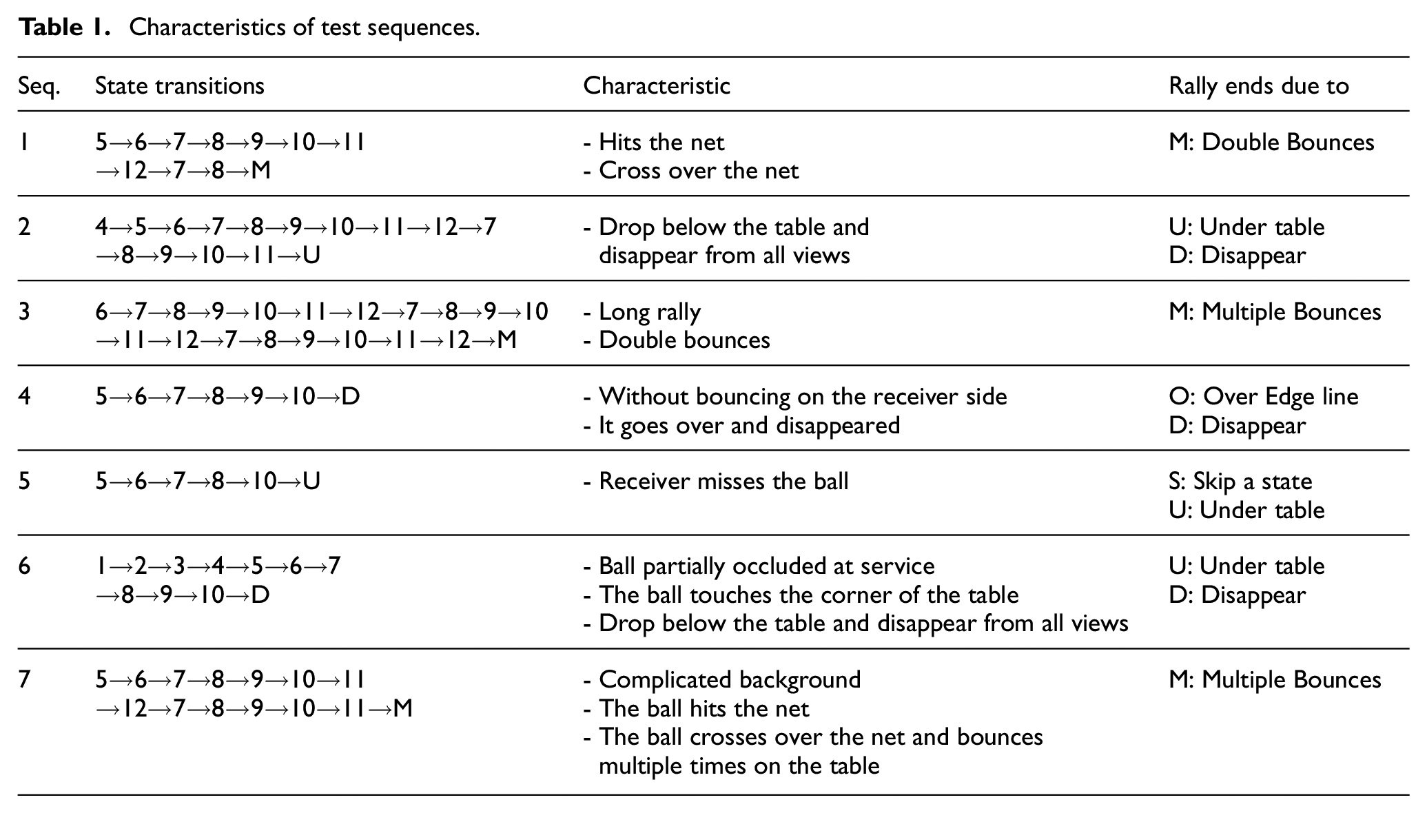
Each sequence was manually analysed by a table tennis expert to determine when each state transition occurs, and the outcome of this investigation helped frame the ground truth used for comparison. Column two of Table 1 displays the state transitions determined by the domain expert.
Figure 12 shows screenshots of the four views captured by the four cameras and the flight paths (red) of the ball over the whole sequence superimposed on each screenshot. The flight path is constructed using the historical positions of the ball detected by the MAS umpiring system.
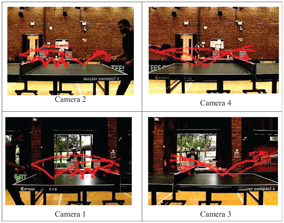
The flight path of the ball.
Figure 13 shows a 3D plot of the historical detected ball positions of Sequence 1 with annotations. The sequence goes through the following state transitions, from the right hand side: 5 (strike by server) → 6 (bounce on server side) → 7 (cross over the net from server) → 8 (bounce on receiver side) → 9 (struck by receiver) → 10 (cross over the net from receiver) → 11 (bounce on server side) → 12 (struck by server) → 7 (cross over the net from server) → 8 (bounce on receiver side) → M (fault: multiple bounces). These state transitions match exactly the ground truth of Sequence 1.
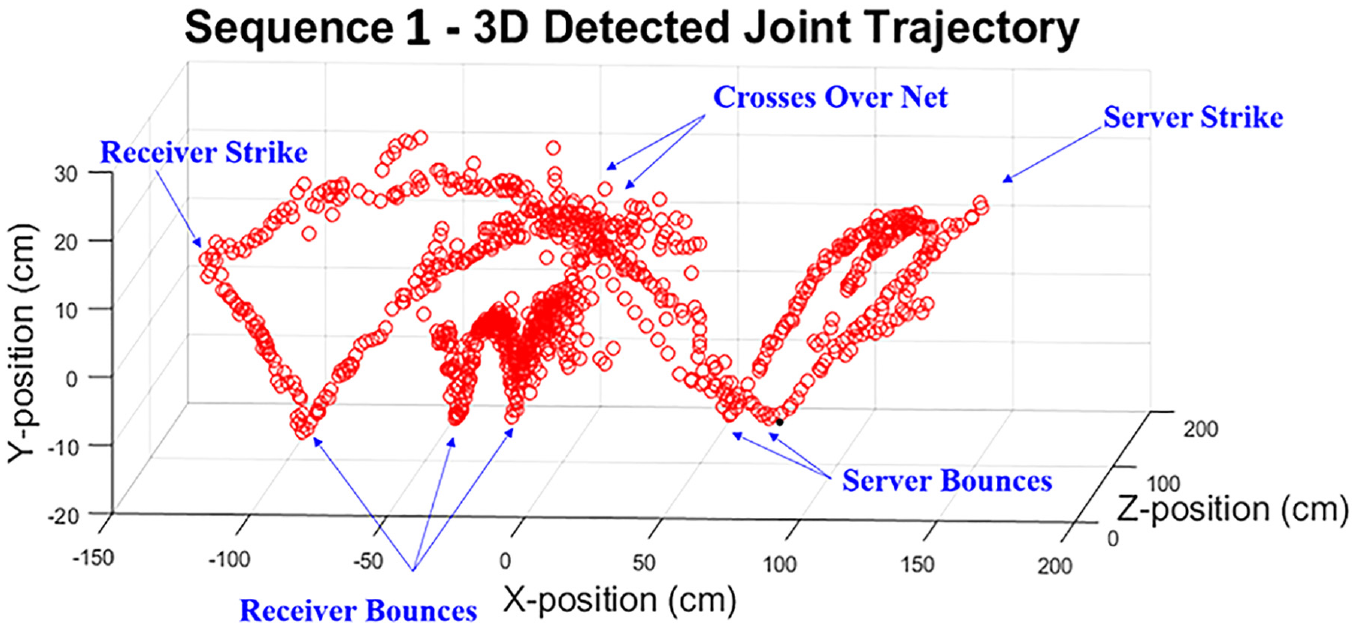
Joint 3D trajectory of the ball.
Figure 14 shows the plots of state transitions detected by the umpiring system (red) the ground truth (blue). The detected state transitions match the ground truth exactly, but there are small lags at States 8, 9, 11, and 12.
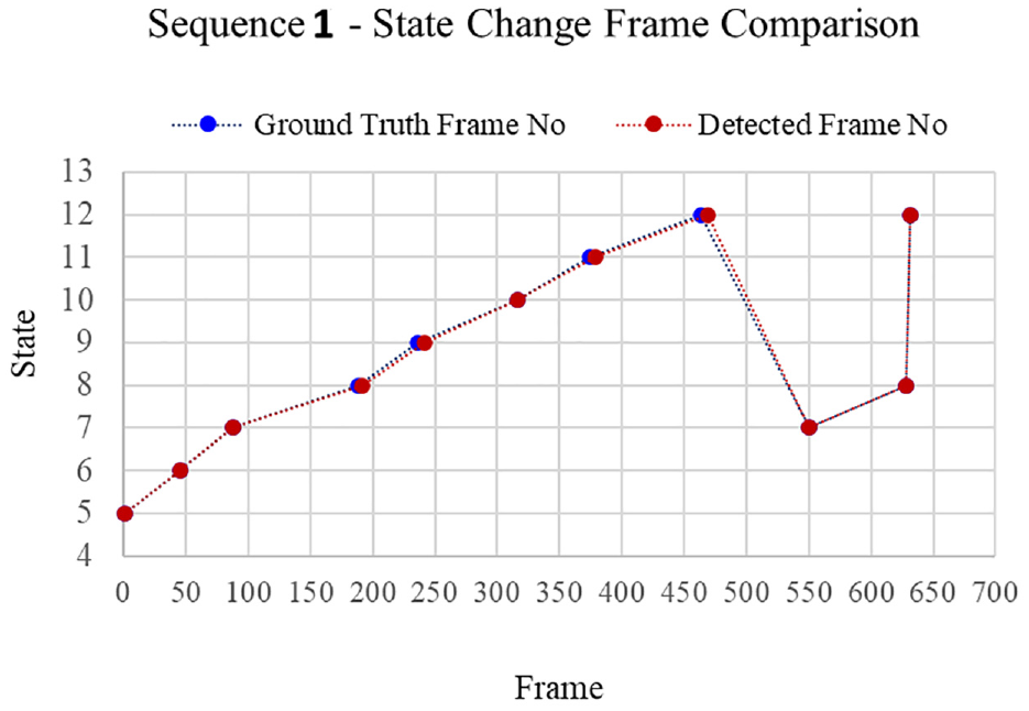
State transitions comparison.
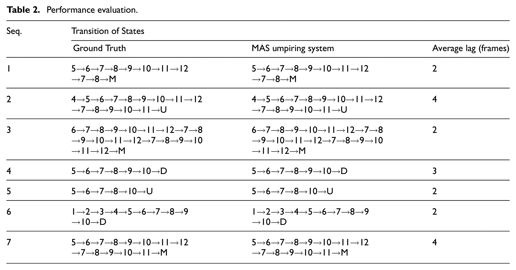
Table 2 shows the comparison of state transitions between the ground truth and the MAS umpiring system for each test sequence. For all test sequences, the MAS umpiring system correctly detected all state transitions with 100% accuracy, although there was occasionally a detection lag of up to 15 frames (50 ms). The average lag across all the test sequences was three frames (or 10 ms) because of the overhead incurred by the FDA in analysing several consecutive frames to detect key features. This relatively small lag time is, however, not significant in terms of umpiring decision requirements which must be made within a 1 second time window.
Performance evaluation.
Overall, the ball detection algorithm took between 5 and 10 ms to process a single video frame of spatial resolution 512 × 368 pixels, so at a frame rate of 300 fps it took between 1.5 and 3 s to process 1 s of video. This processing rate is not fast enough for real-time analysis of long rallies, but because the MAS has a parallel architecture, it allows the system to be run on a network of computers, and thus increase the processing rate of detection. The corollary is that the overall cost of the system would correspondingly increase.
Constraints and future work
While the new MAS umpiring system has encouragingly demonstrated its ability to correctly judge the legality of typical table tennis rallies, two key system performance constraints need to be acknowledged. These are discussed below.
Viewing angle
The current camera arrangement means that viewing angles limit the visible area to 1.5 m above and 0.5 m below the table and though the ball will mainly travel within this space in a typical rally, it is feasible the ball’s position may move outside this space. When movement outside the cameras viewing area occurs, the system monitors the area of capture for up to 2 seconds waiting for the ball to return into view, and if it does not, then the system assumes the ball has dropped to the floor and a fault is registered. It is recognised this conclusion is not ideal because it is possible the ball reaches a very high point from which it takes more than 2 seconds for the ball to return into view. One solution is to position the cameras further away from the table increasing the monitored space, though this arrangement would make the image of ball smaller and thereby more difficult to detect and track. An alternative option is to deploy more cameras to broaden the monitored space, though this proposed setup commensurately impacts the cost and processing overheads.
Edge ball
The current MAS framework is not sufficiently accurate in detecting edge balls, which occasionally occur when a ball touches the edge of the playing surface of the table, which is deemed a legal feature in a rally. If an edge ball results in the ball bouncing upwards, the MAS detects this feature and deems the rally is at a state of bouncing on the table (State 8 or 11 in Figure 10). However, there are no edge ball states in the existing suite of test sequences, so this scenario has not been experimentally tested. If an edge ball touches the table edge very thinly and does not bounce upwards, then the system can wrongly identify this action as a no bounce fault state. To resolve this anomaly, one solution is to attach audio microphones to the rear of a playing surface and incorporate an acoustic ball detection agent in the MAS. The sound of the ball bouncing on the playing surface and either hitting or touching an edge are subtly different, therefore an ANN can be trained to discriminate the differences between their respective audio signals and this information can be combined with the ball position data to improve the detection performance of the system for this scenario.
Conclusion
This paper has presented a novel Multi-Agent System (MAS) umpiring framework that can analyse a table tennis rally in real match scenarios, with complex backgrounds and challenging ball detection conditions. Using an innovative portable camera arrangement, the system employs a minimal number of cameras to cover a large area, while achieving effective redundancy. Despite the innate challenges in perfectly aligning the cameras, an error compensating model has effectively calibrated the MAS, while a state machine has been developed to represent all possible states in table tennis rallies. The MAS umpiring system has been critically evaluated on seven test video sequences covering a range of different real match scenarios and was able to successfully detect all state transitions in the sequences incurring minimal latency.
These promising results indicate that the system can umpire table tennis rallies in real matches. The scalable feature of the MAS means that more camera pairs can be added to the system if higher ball detection accuracy or monitoring a larger court should be desired. With the cost of miniature computer and camera systems, such as the Raspberry Pi, becoming affordable, a low-cost MAS umpiring system is achievable based on this framework.
Footnotes
Declaration of conflicting interests
The author(s) declared no potential conflicts of interest with respect to the research, authorship, and/or publication of this article.
Funding
The author(s) received no financial support for the research, authorship, and/or publication of this article.