
Abstract
Mild traumatic brain injury within contact sports is a growing concern due to the serious risk of injury and concussion. Extensive research is being conducted looking into head kinematics during impacts in non-helmeted contact sports utilizing instrumented mouthguards, allowing researchers to record accelerations and velocities of the head during and after an impact. This does not, however, allow the location of the impact on the head, and its magnitude and orientation, to be determined. This research proposes and validates an algorithm using rigid body dynamics that approximates the impact force and determines its location and orientation from instrumented mouthguard kinematic data. Impact data captured from an experimental laboratory test using an instrumented mouthguard and five finite element simulations are used to validate the algorithm. The obtained results from both validation methods highlight the effectiveness of the proposed impact magnitude and location algorithm as impact locations were calculated within 12 mm of the impact center for all conducted tests. Additionally, components of force unit vectors (direction cosines) obtained from the algorithm were within ±0.03, which equates to less than 11% of the components of applied force unit vectors, highlighting the accuracy of impact direction vector established from the algorithm. This algorithm has the potential to significantly aid researchers conducting field tests within non-helmeted sports by reducing the time required to analyze and determine head impact locations.
Introduction
Non-helmeted contact sports are popular worldwide in a number of different forms, one of the most popular being Rugby Union which has a registered player base of 9.6 million and a fan base of 405 million worldwide. 1 The popularity within the sport arises due to it providing a combination of physical, mental, and skill challenges to the competitors that take part. The physical nature of rugby, however, does bring with it the potential for injuries, the most serious being mild Traumatic Brain Injury (mTBI). 2 mTBI is caused by a sudden blow or jolt to the head, a situation that occurs frequently within non-helmeted sports during games.3,4 Head-to-head impacts are common within these sports, with head injuries accounting for 17% of injuries within Rugby Union. 5 Prien et al. 6 and Pfister et al. 7 conducted systematic reviews to analyze the number of concussive events seen within different sports at both professional and youth level. Their results showed concussion rates within rugby to be the highest, with 3 and 4.3 concussions recorded per 1000 Athletic Exposures (AE) within professional and youth level rugby match play, respectively.
These statistics highlight the importance in understanding the nature of impacts sustained by players in non-helmeted sports. Currently, understanding head kinematics during and after an impact, predominantly the linear and rotational acceleration of the head, is being extensively researched. Different methods have been proposed and used in the past to understand the kinematics of the human head during and after an impact, with video footage being the only source of data available at the early stages of this area of research. McIntosh et al. 8 used video recordings of impacts to estimate the head impact velocity in two dimensions, allowing the estimation of the energy transfer to the head from an impact. This method, however, proved not to be an accurate way of understanding head kinematics due to the impact velocity being approximated as well as a number of parameters required for the calculations being estimated.
Wearable sensors housing accelerometers and gyroscopes were therefore utilized to provide head kinematic data to establish head impact trends within contact sports. For helmeted sports, head mounted sensors placed within helmets were utilized to quantify impacts. Researchers predominantly used the Head Impact Telemetry system which incorporated six single-axis linear accelerometers embedded in the padding of the helmet for studies in helmeted sports.9–12 The accuracy of the kinematic data obtained from HIT and helmet mounted sensors was rigorously studied, with researchers establishing more than 15% error in resultant peak linear accelerations.13–15 For non-helmeted sports, the skin patch was developed which is a skin mounted wireless sensor placed behind the ear of the player. It records and calculates key data when an impact occurs, such as linear acceleration and rotational velocity components of the head. 16 This technology was used extensively by King et al., 17 Hecimovich et al., 18 and Willmott et al. 19 within different levels of Australian Rules Football, from youth to sub-elite, and in amateur Rugby League. These authors were also able to establish head acceleration trends from impacts. However, studies have highlighted measurement error for peak resultant acceleration to be as high as 50% from the skin patch due to skin dynamics and lack of skull coupling.13,20
Further technological advancements saw the development of instrumented mouthguards,21–25 such as the one shown in Figure 1, which house a sensor strip that captures kinematic data via a gyroscope and linear accelerometer. This is currently being used by different researchers as it allows more accurate data recording in comparison to the skin-mounted sensors. Wu et al. 26 established that mouthguards showed tighter skull couplings than skin mounted sensors, providing more accurate kinematic results. This technology has predominantly been used for research purposes within helmeted sports such as American football,21–24 with only a small number of research projects focusing on non-helmeted sports. King et al. 27 conducted a preliminary study with an instrumented mouthguard, quantifying head impacts within amateur Rugby Union players. These authors were able to determine trends regarding the magnitudes of accelerations felt by players in different positions during a full season of matches.
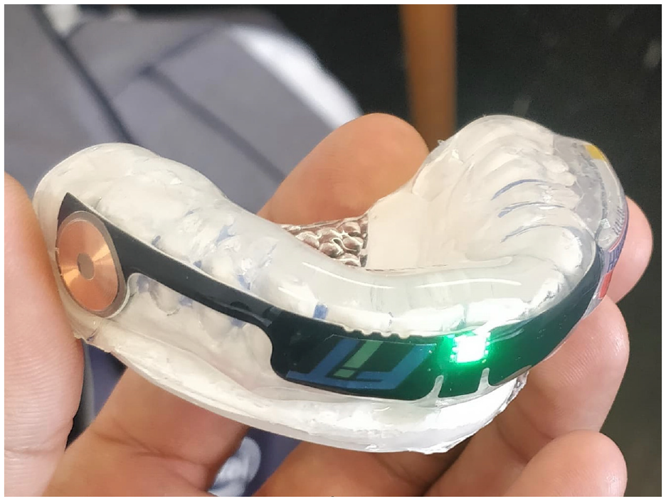
Instrumented mouthguard developed by Force Impact Technologies (FIT), used in this research.
The main aim of the research presented here is to propose and develop a method, algorithm and numerical tool that will allow researchers to analyze kinematic data from instrumented mouthguards. The data collected from the sensors is in the form of tri-axial acceleration and velocity components. The proposed method determines the location and orientation of the impact on the head, based in this recorded data. Little research has been conducted to propose a robust method to determine the impact locations from sensor data. In most reported cases, peak linear acceleration components are used to approximate the direction of impact and hence an impact location region (back, side, front). 28 Video footage is often utilized alongside to verify impact location regions, as PLA component based regions have shown inaccuracies. 23 In most cases, however, this is an extremely costly and time-consuming process. Crisco et al. 29 developed an algorithm that allows the location of an impact to be calculated. This algorithm is based on data collected from several single axis non-orthogonal accelerometers and was found to be an effective method for helmeted sports, where multiple accelerometers can be placed within the helmet. For instrumented mouthguards with a tri-axial linear accelerometer and gyroscope, Bartsch et al. 22 and Kuo et al. 23 proposed methodologies to approximate the location of the impact. Bartsch et al. utilized rigid body dynamics with assumptions, to simplify the problem to determine an approximated impact location whereas Kuo et al. utilized integrated linear and rotational position values to determine an impact region. The methodology proposed by Kuo et al., however, was only able to classify 37% of impacts to the correct impact region, highlighting the need for a methodology to improve upon the accuracy of impact location classification. The following section describes a proposed method, which builds on the work published by Bartsch et al., 22 utilizing rigid body dynamics and a multi-degree of freedom (MDOF) lumped-mass system replicating the head and neck, to determine the orientation, magnitude, and location of an impact force from instrumented mouthguard data. Unlike the approaches by Bartsch et al. and Kuo et al., the following method aims to determine the impact location rather than a region of the head where the impact occurs. The accuracy of the impact location determined by the proposed method is established by an author-defined metric as described in the following section. It is hypothesized, with the extensive data collection push expected in the near future, knowing where on the head the impact occurs will be very useful, as different areas of the same region (back/side/front) could be more or less susceptible to concussions, making the following methodology extremely useful in research in the battle against mTBI.
Methodology
The method proposed to determine the magnitude, orientation, and location of an impact based on mouthguard linear acceleration and rotational velocity components is based on rigid body dynamics. The main steps in the Impact Magnitude and Location Algorithm (IMLA) developed in this work can be summarized as:
Calculation of the components of the moment, from Euler’s equations.
Estimation of the magnitude of the impact force with a multi-degree of freedom (MDOF) system. This is achieved with modal analysis to establish the mechanical response of the system in three linear directions.
Moment matching between Euler’s and torque equations to determine the location of the impact.
Impact moment calculation
The moment experienced by the head because of the impact is first calculated using Euler’s equations, where the Cartesian components of the moment vector
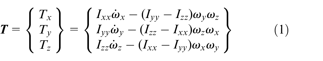
where
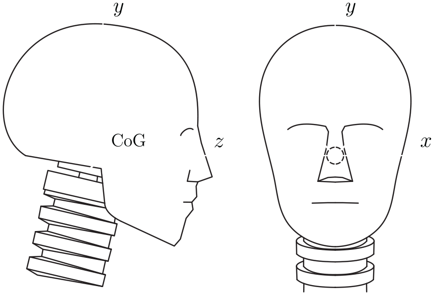
Global axis orientations.
Impact force magnitude
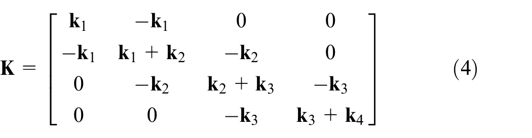
A three-dimensional mass-spring MDOF system is used to estimate the magnitude and direction of the impact force on the head. This 4-mass system replicates the human head and neck with the springs replicating the stiffness of the intervertebral joints.

where
The stiffnesses of the intervertebral disks were determined by Luo and Goldsmith
30
using stiffness data previously reported by Deng and Goldsmith
31
and Panjabi,
32
considering that the stiffness of each individual joint is proportional to the cross-sectional area of the corresponding disk. These authors calculated a stiffness matrix for the C2/C3 joint and a proportionality factor for the remaining ones, allowing stiffness matrix calculations for any intervertebral joint. The (
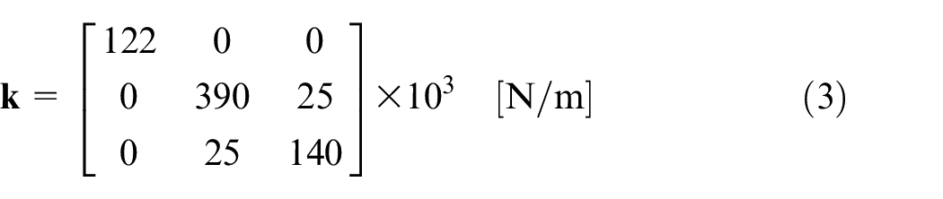
The individual springs
The global inertia matrix compiles the four individual mass matrices as
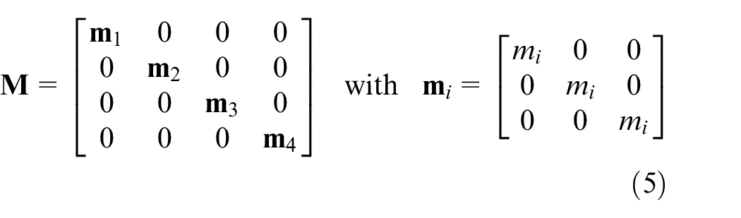
The inertia of the individual vertebrae couples and head are also taken from Lou and Goldsmith. 30
The external force vector is the
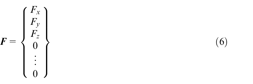
where
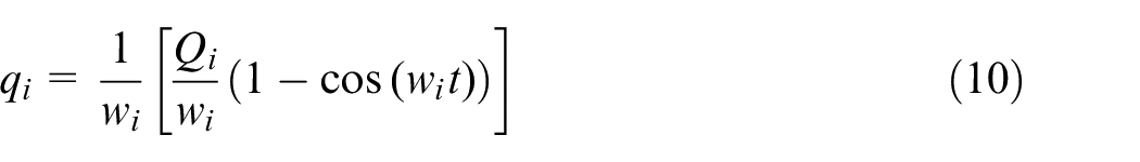
Modal analysis is used to calculate the natural frequencies and mode shapes of the MDOF system, which are in turn used to determine the mechanical response of the system when a force is applied. 33 The equation of motion, equation (2), can then be rewritten as

where

where

where
The linear acceleration components of the head are obtained directly from mouthguard data and then converted to linear acceleration components at the center of gravity (CoG) of the head with

where
Integrating
Impact location
The impact location was determined by matching the moments calculated with equation (1) and the torque equation

where
For the purpose of the IMLA, the moments are calculated for coordinates on the surface of a head using equation (12). Coordinates can be established by utilizing nodes from a generic FE model or from MRI scans for specific players. Obtaining an MRI scan for every player within a team could be very impractical therefore the authors proposed that a generic FE model approach to be used with the IMLA. A three stage process is implemented to determine the location of the impact. Initially, the algorithm matches moment signs, eliminating nodes with position vector
Validation
The IMLA was validated by obtaining head impact kinematic data by two methods. The primary method used a head-neck finite element Hybrid III Dummy model simulating impacts on the dummy head. Impact simulations were conducted on different locations of the head, and the kinematic responses were used to validate the IMLA. Additionally, kinematic impact data was obtained in a laboratory test from an instrumented mouthguard similar to the one in Figure 1. The two methods complement each other to provide a validation of the proposed IMLA. The Hybrid III finite element (FE) simulations allow control over key impact parameters such as head dimensions, minimizing errors when testing the IMLA. Additionally, the simulations provide a method to test the developed algorithm against impacts of varying magnitudes and locations with ease. The observations from the experimental test ensure the IMLA is accurate and can be used to determine the location of live impacts when using instrumented mouthguards.
Numerical modeling
Five models were developed using a validated LS-DYNA Hybrid III Dummy head/neck model, consisting of 50,698 elements, 63,500 nodes with 176,682 degrees of freedom, created with hexahedral constant stress solid finite elements.34,35
Simulations were conducted to replicate impacts on different locations of the head as shown in Figure 3(a) to (d). Side, left-upper-side-frontal, right-upper-side-frontal, and lower-side-frontal locations were selected for impacts for the FE simulations with the laboratory test providing a frontal impact. Tests 1 and 4 were conducted from the same “Side” location with differing initial velocity components to test the IMLA with different impact levels at the same location. Boundary conditions were applied to the base of the shoulder piece to fix movement in all rotational and linear directions. Additionally, the simulation duration was set to
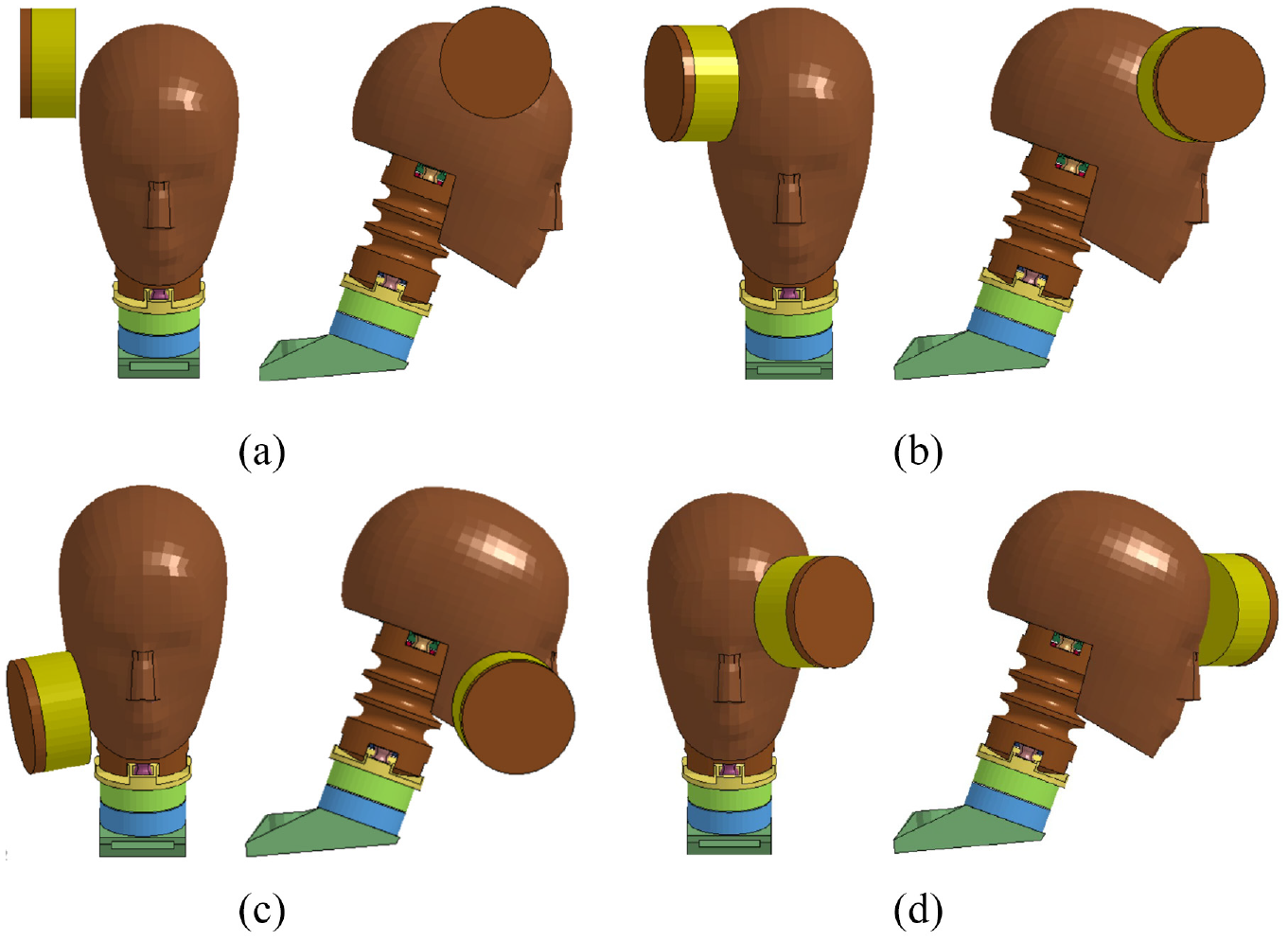
Finite Element (FE) simulation setups in LS-DYNA: (a) Test 1 and Test 4 replicating a side impact with impactor initial velocity in the
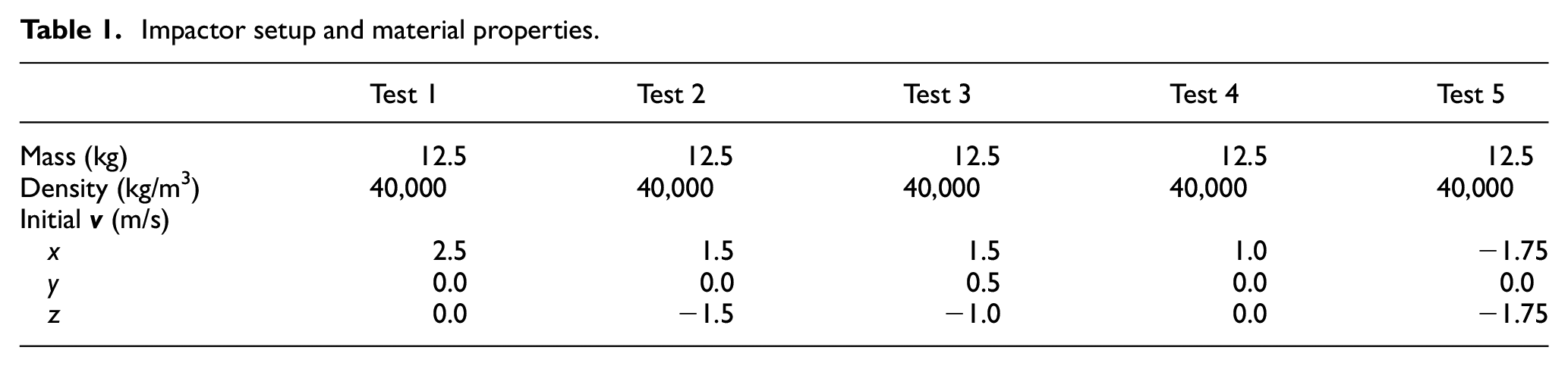
The material properties and initial conditions selected for the impactor were chosen to provide impact magnitudes and durations that closely reflect on-field impacts within rugby.
27
A cylindrical impactor with a diameter of
Impactor setup and material properties.
A hyper-elastic rubber constitutive law was used for the impactor (MAT 077 H on LS-DYNA) defined as
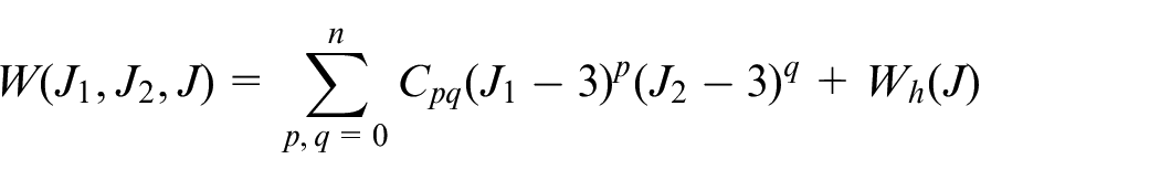
where
Experimental tests
The experimental impact tests were done with a Biokinetics medium-velocity head impact simulator, shown in Figure 4,
37
instrumented with a mouthguard developed by Force Impact Technologies (FIT), similar to the one in Figure 1. A dental impression is taken of the dentition of the test head which is used to mold a custom fitted mouthguard that affixes securely to the dentition. The same process that is used to make a custom fitted mouthguard for a human athlete is used to mold the instrumented mouthguard for the test head. This mouthguard incorporates a sensor strip anterior to the upper incisors, similar to the one that is being implemented in instrumented mouthguards worldwide.23–25 The sensors include a tri-axial linear accelerometer (ST H3LIS331DL) and a gyroscope (ST LSM6DS3H) providing linear acceleration (
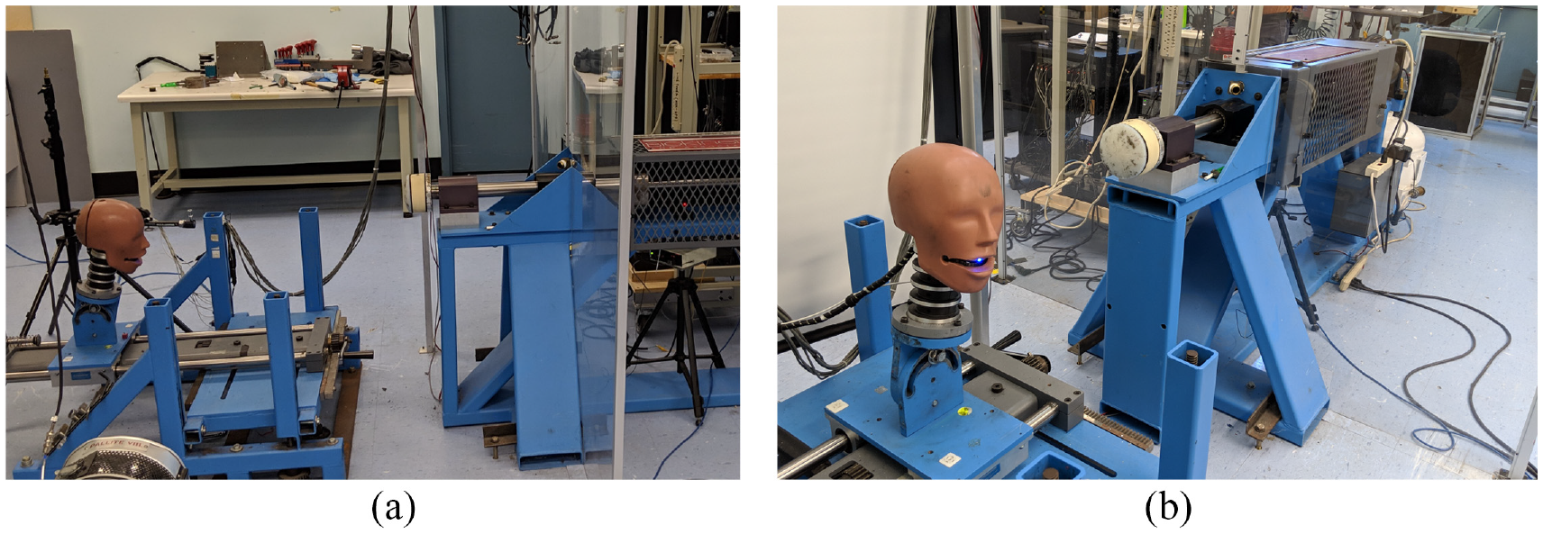
Biokinetics medium-velocity head impact laboratory simulator used to conduct the experimental lab tests: (a) showcasing the linear impactor, target table, head-form and (b) highlighting the position of the mouthguard within the head-form.
Results
Kinematic data
Kinematic data obtained from the experimental test measurements and finite element simulations are shown in Figure 5 and Table 2. The linear acceleration data in Figure 5 is collected from the instrumented mouthguard that shows the impact occurring at around

Kinematic response of the head during the lab test collected via FIT instrumented mouthguard in the ),  ), and
  ) directions: rotational velocity (left) and linear acceleration (right).
Kinematic results from LS-DYNA simulations.
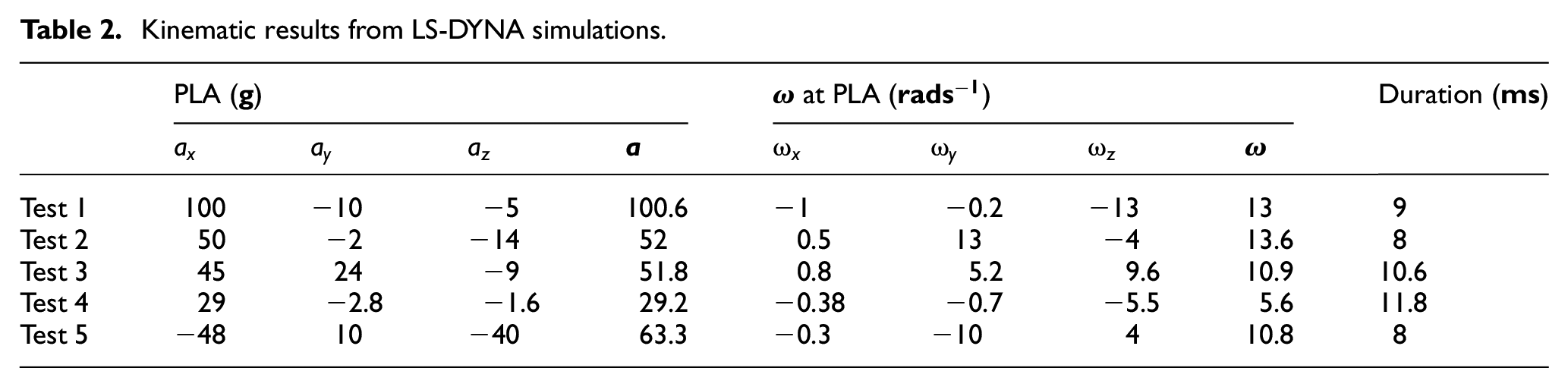
The kinematic response of the FE models shows similarities to the laboratory test with regards to the duration and magnitude of the impacts. The impactor material properties were selected to ensure the FE simulations that utilized a validated Hybrid III Dummy head model, provided acceleration magnitudes that replicated head impacts within non-helmeted sports. The impact durations for all FE simulations are within a
Impact location and direction
The IMLA was used for all validation simulations to establish the location of the impact. Figures 6 and 7 show the direct output from the IMLA, which generates all the analyzed coordinates on the surface of the head and highlights the BFN as the calculated location of the impacts. The experimental test was a right frontal impact, replicated by the algorithm, as shown in Figure 6(e). Additionally, for the Hybrid Dummy III finite element simulations, the BFNs calculated by the IMLA for all impacts correlated to nodes that were struck by the impactor in the simulations.This can be seen when comparing Figure 3 with the IMLA output in Figures 6 and 7. As the impactor strikes more than one node, the distance from the BFN to the impact epicenter, which was defined as the initial point of contact between the impactor and the Hybrid III head, was calculated to quantify the accuracy of the impact location. The BFN for Tests 4 and 5 replicated the same node as the epicenter of the impact however, for Tests 1–3, the calculated BFN was found to be a neighboring node with the impact epicenter being a distance of
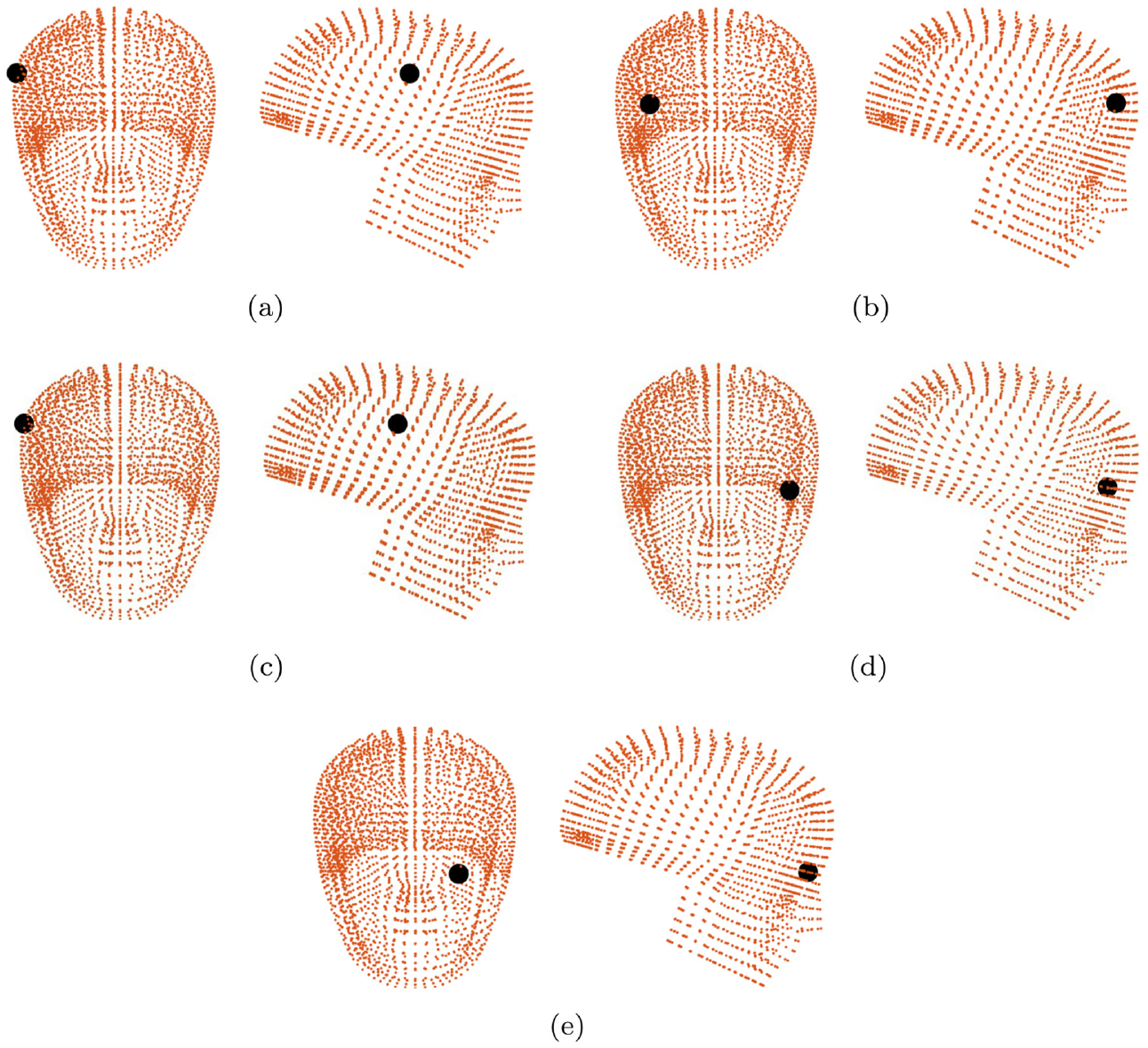
Impact location, highlighted in black, on the
Furthermore, Figure 7 highlights the impact location process for Test 3, as described in the methodology section. The initial stage of the process matches moment directions which eliminates the majority of the nodes as shown in Figure 7(a). Further nodes are eliminated by the addition of tolerances while matching moments and ensuring the impact vector can physically target the node, leaving a cluster of nodes in the cheek/jaw region, as seen in Figure 7(b). At this stage, a good approximation of the impact location can be determined, however the BFN can be established by reducing tolerances for each direction as highlighted in Figure 7(c).
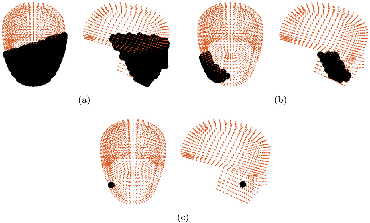
Impact location process for Test 3 on the
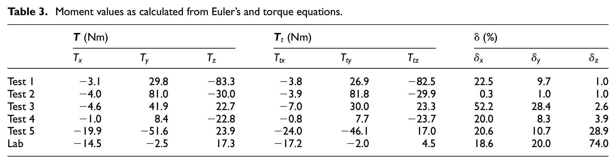
Moreover, components of
Moment values as calculated from Euler’s and torque equations.
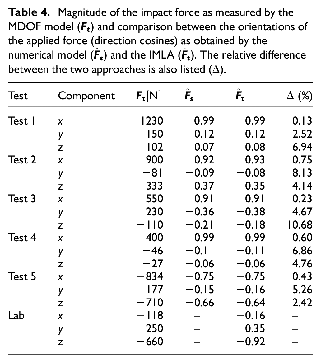
Additionally, Table 4 lists the approximated force,
Magnitude of the impact force as measured by the MDOF model (
Discussion
The proposed algorithm utilizes rigid body motion dynamics to establish impact locations, building upon the work of Bartsch et al.
22
However, unlike the assumption that the head rotates about the CoG made by Bartsch et al., the IMLA establishes rotations about the head/C1 joint and uses an additional MDOF system to replicate the kinematics of the head and neck to determine the impact direction, rather than assuming it is a free body. Furthermore, the IMLA determines position vectors and inertias from a Hybrid III Dummy model, incorporating the non-spherical shape of the human head, as opposed to using a simpler spherical geometry. Finally, the moment matching technique allows nodes to be eliminated till the BFN is found, rather than determining the position vector, as stated by Bartsch et al. Rather than approximating an impact region, this technique provides the ability to pinpoint the impact location to within
Tables 3 and 4 highlight the numerical output from the algorithm with regards to Eulers moments, Torque moments, approximated force magnitude, and impact direction. The approximated force components calculated by the MDOF is underestimated, however the impact direction vector is unaffected, with components of
Moreover, the difference seen in Table 3 for the experimental test was larger than that of the FE simulations with
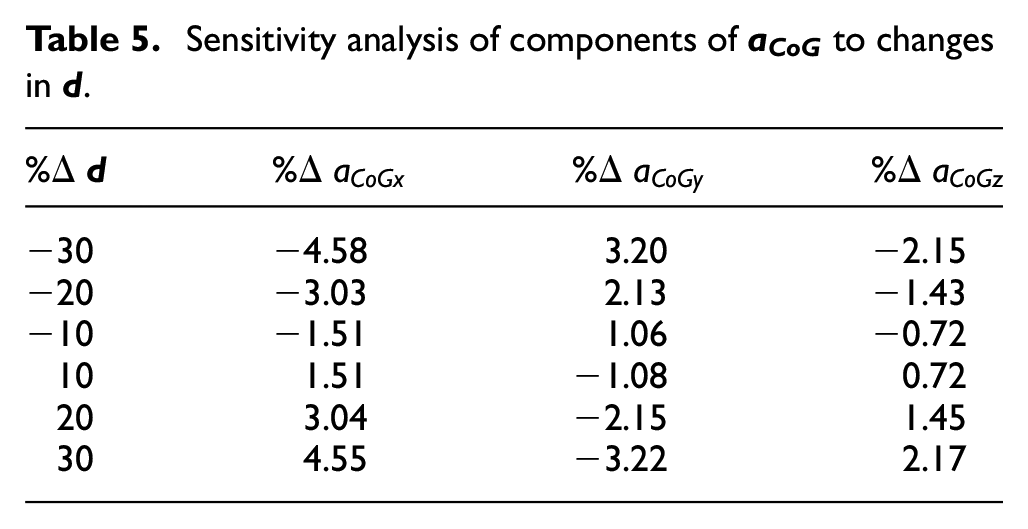
Furthermore, the experimental test replicated a live impact to validate the IMLA with variables that would be unknown to researchers utilizing instrumented mouthguards. Player heads vary in size and shape and it is not possible to accurately measure head dimensions when analyzing impacts which in turn will incur errors within variables such as
Sensitivity analysis of components of
Sensitivity analysis of components of
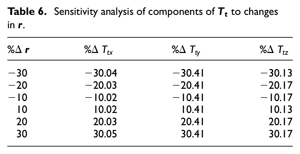
Moreover, inertia values used in equation (1) are established from the Hybrid III, which will result in small errors due to the shape of the Hybrid III Dummy differing from the head-form used in the experimental test.
The algorithm is, nonetheless, efficient in determining the location of the impact by eliminating nodes until only one remains, meaning the moments difference between
Conclusion
An algorithm to determine the impact magnitude and location of an impact on the head was developed to aid ongoing research regarding head impacts in non-helmeted contact sport. The algorithm utilizes a combination of rigid body dynamics and a multi degree of freedom (MDOF) system, and is validated with kinematic data from Hybrid III Dummy FE simulations and laboratory testing with an instrumented mouthguard. The five FE simulations and the laboratory test replicated impacts of varying magnitudes and locations to test the performance of the proposed algorithm (IMLA). The output from the algorithm correctly determines the impact locations for the simulations as the best fitting node (BFN) calculated by the IMLA is within
Footnotes
Appendix
Acknowledgements
For the purpose of open access, the authors have applied a Creative Commons Attribution (CC BY) license to any Author Accepted Manuscript version arising from this submission.
Declaration of conflicting interests
The author(s) declared no potential conflicts of interest with respect to the research, authorship, and/or publication of this article.
Funding
The author(s) disclosed receipt of the following financial support for the research, authorship, and/or publication of this article: The authors acknowledge the support given to this project by the Engineering and Physical Sciences Research Council (EPSRC) [grant: EP/R513209/1].