
Abstract
This study aimed to quantify forearm kinematics with a focus on the forearm rotation axis. Ten healthy volunteers were included in the study. One three-dimensional computed tomographic scan and two four-dimensional computed tomographic scans were done in all the arms to capture forearm joint motion. After image processing, the rotation axis and the movement of the radius with respect to various axes were quantified. The rotation axis was calculated using finite helical axis analysis and a circle fitting approach. The mean error of the rotation axis found through circle fitting was 0.2 mm (SD 0.1) distally and 0.1 mm (SD 0.1) proximally, indicating an improvement in precision over the finite helical axis approach. The translations of the radius along the ulnar axis and the forearm rotation axis were 2.6 (SD 0.8) and 0.6 mm (SD 0.9), respectively. The rotation of the radius around the radial axis was 7.2°. The techniques presented provide a detailed description of forearm kinematics.
Introduction
Injury to the distal radioulnar joint (DRUJ) or the surrounding ligaments can lead to joint instability and osteoarthritis (Lameijer et al., 2018; Mirghasemi et al., 2015), causing pain and a decreased range of motion (ROM) in forearm rotation. A decreased ROM, especially limited supination, has a significant effect on carrying out activities of daily life (Gates et al., 2016). Arthroplasty is a treatment option for osteoarthritis. The implant restores forearm function by re-establishing the motion pattern of the healthy forearm. Unfortunately, the complication rate in the available implants is high and revision surgery is common (Bellevue et al., 2018; Calcagni and Giesen, 2016; Kakar et al., 2014; Lambrecht et al., 2022; Moulton and Giddins, 2017). This could indicate that the kinematics of the forearm are not fully understood, or inadequately incorporated into implant designs and the procedures for placement in the forearm, leading to long-term complications and failure.
A significant amount of work has been previously done to accurately establish the kinematics of the forearm from three-dimensional (3-D) and four-dimensional (4-D) medical images (Kazama et al., 2016; King et al., 1986; Matsuki et al., 2010; Nakamura et al., 1999; Oki et al., 2019; Shakoor et al., 2019; Tay et al., 2008, 2010). However, these studies have used various imaging techniques, pseudo-dynamic imaging or a limited number of 3-D image frames to visualize and quantify forearm motion. Conflicting results about the position and orientation of the forearm rotation axis have been reported. For instance, one study described a single, fixed rotation axis to quantify the motion of the radius around the ulna (Tay et al., 2010), whereas another study described a rotation axis that changed position and orientation during the pronation-supination cycle (Matsuki et al., 2010). These conflicting results further support the notion that forearm kinematics are not yet fully understood and measurement techniques should be carefully considered (White et al., 2019).
The discrepancies about the position and orientation of the forearm rotation axis could originate from the use of finite helical axis (FHA) analysis. The FHA describes a single axis in 3-D space along which a body translates and around which it rotates. It is calculated from the repositioning matrix that describes the movement, translations and rotations, of a body between two positions (Ancillao, 2022; Kinzel et al., 1972; Spoor and Veldpaus, 1980). One single FHA could poorly represent movement of the radius during the pronation–supination motion if the radius rotates not only around the ulna but also rotates around and translates along its own axes of inertia. Moreover, the FHA approach has been proven to be imprecise for angular displacements of less than 10° (Ancillao, 2022; Spoor, 1984; Tay et al., 2008).
The aim of this study was to review the FHA analysis for describing forearm kinematics and to introduce an alternative method, which quantifies rotation of the radius around the ulna, and translation and rotation of the radius along and around its own principal axes of inertia and that of the ulna.
Methods
Ethical approval for this study was obtained from the Medical Ethics Committee at our hospital and the study was registered (Dutch Trial Register NL64090.018.17). Ten voluntary participants with a mean age of 31 years (range 22–69; five men and five women) were included. Exclusion criteria were pregnancy and a history of injury to the forearm. Written informed consent was obtained from all volunteers before the study.
The study participants were subjected to six CT scans: a spiral CT of each forearm for segmentation of the radius and ulna, and 4-D-CT scans (33 frames each) of both the DRUJ and proximal radioulnar joint (PRUJ) during forearm rotation to visualize joint motion (Kalia et al., 2009). The segmented distal and proximal radius and ulna segments were registered to the frames in the 4-D-CT scans to quantify motion of the radius with respect to the ulna. The corresponding transformation matrices were used to calculate the helical axes of motion. In this study, several axes apply, which are visualized and defined in Figure 1. For the new approach, a circle fit was used to describe positions of rotating distal and proximal segments of the radius. The line between the centres of these circles served as the forearm rotation axis. Besides defining the forearm rotation axis, we quantified rotation of the radius around the radial axis and translation of the radius along the forearm rotation axis and the ulnar axis.
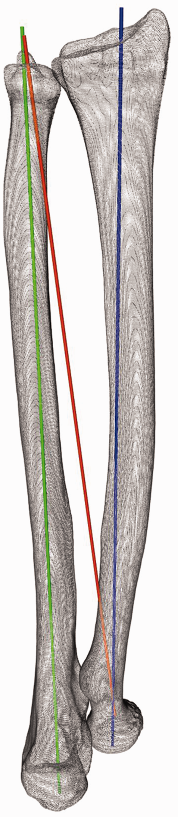
The radius, ulna and the axes used in this study. The green ‘ulnar axis’, is the longitudinal principal axis of inertia of the ulna. The orange axis will be referred to as the ‘forearm rotation axis’. The blue ‘radial axis’ represents the longitudinal principal axis of inertia of the radius.
Image acquisition
A Siemens SOMATOM Force CT scanner (Siemens Healthineers AG, Erlangen, Germany) was used for both the spiral CT scan and 4-D-CT scans. Participants were placed in a prone position with one arm overhead and the elbow in approximately 30° flexion (Figure 2). A special cushion was placed under the upper arm to prevent shoulder abduction, ensuring pronation was solely caused by forearm rotation. A hand-guiding device was attached to the scanner table to provide a grip for the participant, guide movement during the 4-D-CT scans and to keep the area of interest consistently in the range of the scanner detector.
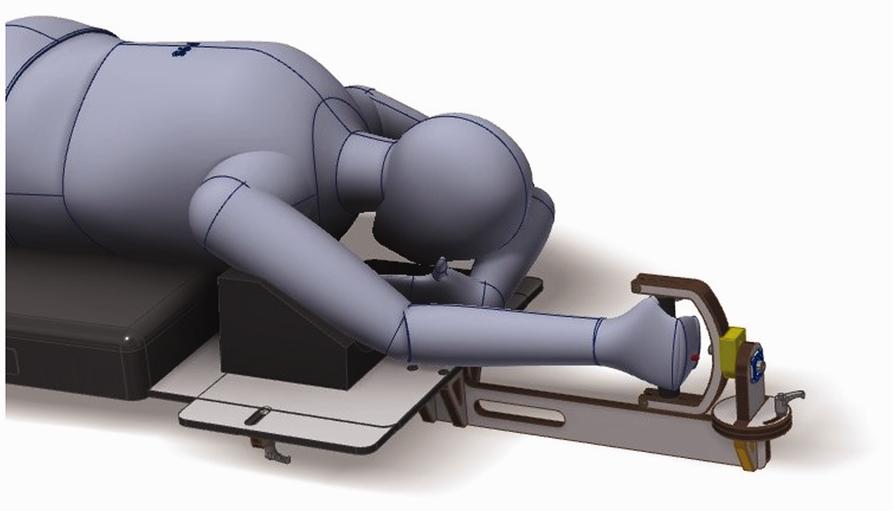
Hand-guiding device and volunteer position during scanning.
Scanning started with a spiral CT (120 kV, 65 mAs) of the forearm in the neutral position. Before the 4-D-CT scans, the forearm rotation movement was practised. Participants were instructed to rotate the forearm from a fully supinated to a fully pronated position during a 20 second countdown to synchronize their movement with the scanning time interval. The 4-D-CT scan of the DRUJ (120 kV, 15 mAs, 33 images) was started once the participant was comfortable with the movement. The countdown was provided through the scanner intercom. Before progressing to the 4-D-CT scan of proximal radioulnar joint (PRUJ) (120 kV, 15 mAs, 33 images) the participant was given the opportunity to practise the movement again if they so desired. After completion of the PRUJ scan, the participant was re-positioned and the entire process was repeated for the other arm.
Image processing
3-D models of the radius and the ulna were created through segmentation using the spiral CT scan. Subsequent registration of the distal and proximal radius and ulna matched the 3-D models to the 33 time frames of the distal and proximal 4-D-CT scans. Both processes were executed as described by Dobbe et al. (2019) and provided the kinematic parameters and a visualization of forearm rotation in 3-D. The 3-D model of the ulna was selected as a fixed reference bone in order to isolate the movement of the radius around the ulna. Transformation matrices, describing the movement of the 3-D model of the radius between time frames with respect to the global coordinate system, could then be exported for further processing.
Forearm rotation axis by FHA analysis
Movement of the radius was defined as a set of transformations of the 3-D model between a reference frame and each time frame. Therefore, the number of transformations and thus the transformation matrices that could be generated from a 4-D-CT scan containing 33 frames is equal to the triangular number of 32, which is 528. All the 528 FHAs and corresponding angular displacements (ϴ) were calculated from the transformation matrices obtained from each unique combination of two frames within the 4-D-CT scan (Kinzel et al., 1972). This allowed for a comparison between a large angular displacement FHA and a small angular displacement FHA, since a large angular displacement FHA is less prone to error than a small angular displacement FHA (Ancillao, 2022; Spoor, 1984; Tay et al., 2008).
Forearm rotation axis by circle fit approach
For the new approach, the forearm rotation axis was determined by describing the movement of centroid positions of a distal and a proximal segment of the radius over a complete motion cycle using a circle fit, and using the centre positions of these two circles as the two points defining the forearm rotation axis. For the distal radius, the segment visible in the first 4-D-CT time frame (approximately 57 mm) was chosen. The centroid coordinates of the surface area of the radial tuberosity, which was manually selected in frame 1, were used for the proximal circle fit. Since it is located furthest from the forearm rotation axis in the proximal region, it is considered less sensitive to small errors resulting from image analysis.
The centroid positions of the distal and proximal segments were imported into Python 3.9 (Van Rossum and Drake, 2009) and used as input data for the circle fit algorithm. Initially, all centroid positions were projected onto a plane. To this end, the plane with the smallest root-mean squared orthonormal distance to these coordinates was determined using singular value decomposition (Gander and Hřebíček, 2004). The in-plane x- and y- projected centroid positions were subsequently used for circle fitting using the approach described by Bucher (2022). The methodological error of the circle fit (root mean square error (RMSE)) was obtained from the root mean squared distance of all centroid coordinates to the fitted circle.
The number of images acquired during the 4-D-CT scan is directly related to the radiation dosage. A reduction in radiation dosage can thus be achieved by reducing the number of 4-D-CT frames. Besides lowering the radiation dosage, reducing the number of 4-D-CT frames also affects the accuracy and precision of finding the forearm rotation axis. To quantify this effect, a comparison between the 33-frame circle fit and a 3-, 5-, 10- and 20-frame circle fit was made. A bootstrap algorithm was used to select 1000 random combinations of 3-, 5-, 10- and 20-fit point coordinates from the complete set of 33 fit points originating from all 33 frames of the 4-D-CT scan. Each set of 1000 coordinate combinations was passed to the circle fit algorithm resulting in 1000 new centres of rotation. In addition to calculating the methodological error (RMSE) as described above, the performance of the circle fits using fewer points was also analysed by calculating the mean Euclidean distance from the 1000 centres of rotation to the centre of the circle fit using all 33 points.
Comparing FHA analysis and the circle fit approach
The estimated rotation axes obtained using the FHA and circle-fit approaches were compared by quantifying the differences in position and orientation. The angle between the FHA, determined between maximum positions of pronation and supination, and the rotation axis resulting from the 33-point circle fit was calculated from the corresponding direction vectors. Furthermore, the positional differences at the level of the DRUJ and PRUJ were visualized and calculated. Two planes were defined for this: one at the level of the ulnar fovea and one at the level of the head of the radius (Figure 3). The intersections of all FHAs and the 33-point circle fit rotation axis with these planes were determined and plotted. The mean Euclidean distance between the FHA intersections and the circle fit intersection was subsequently calculated.
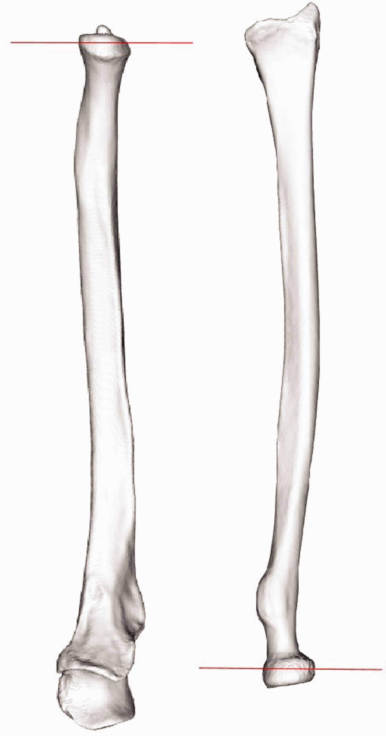
Distal and proximal intersection planes for visualization of differences in axis positions.
Rotation of the radius around the radial axis
The circle fit approach quantifies the forearm rotation axis and describes rotation of the radius around the ulna. Possible rotations of the radius around one of its own principal axes of inertia, such as rotation around the previously defined radial axis, are not taken into account. By describing the above circle fit based forearm rotation in terms of a transformation matrix (Mforearm), and by excluding this contribution from the overall transformation matrix (Mtotal), we can investigate whether there is residual motion around the principal axes of inertia of the radius.
For this, the time frame when the radius was closest to the middle of the ROM was selected as the reference frame. The total transformation (Mtotal) of the radius was given by the transformation matrix between the reference frame and any of the 32 target frames. Using these two known matrices (Mtotal and Mforearm), the transformation matrix describing the movement of the radius with respect to its own principal axes of inertia (Mradius) can be calculated using the following equation:

Both the total transformation (Mtotal) and the transformation around the forearm rotation axis (Mforearm) were described in the global coordinate system. To find the rotations about and translations along the radial axis, the residual transformation matrix should be expressed in the local coordinate system described by the principal axes of inertia of the radius. This was achieved through multiplication with the transformation matrix, which aligned the global coordinate system with the local coordinate system (Mglobal2local) as in equation (2).

The rotation around the radial axis was then extracted from Mradiuslocal. This process was repeated for all target frames. Finally, the angle of rotation around the radial axis was plotted with respect to the angle of rotation around the forearm axis of rotation (forearm position).
Translation along the ulnar axis and the forearm rotation axis
There have been many studies on ulnar variance that describes the relative length of the radius with respect to the ulna (Fu et al., 2009; Jung et al., 2001; Sayit et al., 2018; Yeh et al., 2001; Yoshioka et al., 2007). It has been shown that ulnar variance changes in different forearm positions, elbow positions and with hand grip (Fu et al., 2009; Jung et al., 2001; Yeh et al., 2001). This indicates translation of the radius along the ulnar axis (Figure 1), during forearm rotation. To understand the origin of this translation, the position of the sigmoid notch with respect to the ulnar axis and forearm rotation axis was tracked during forearm rotation. It was assumed that the translation along the ulnar axis is caused by the tilt of the radius across the ulna since the radius is proximally supported by the humerus, which prevents translation of the entire radius along the ulnar axis. To confirm this hypothesis, the translation along the forearm rotation axis should be approximately zero, whereas the translation along the ulnar axis should be equivalent to the change in ulnar variance previously reported (Jung et al., 2001; Yeh et al., 2001).
To measure the translation, the surface of the sigmoid notch on the radius was selected by hand and its centroid position was projected onto the ulnar axis for the entire ROM. The distance between the most distant points of projection served as the magnitude of translation. The translation along the forearm rotation axis was measured in the same way.
Results
Forearm rotation axis by circle fit approach
The mean methodological error of the circle fit (Figure 4), based on all 33 centroid locations was 0.2 mm (SD 0.1) for the distal and 0.1 mm (SD 0.1) for the proximal circle fit. The errors for the curve fits using fewer than 33 fitting points are given in Table 1 and Figure 5.
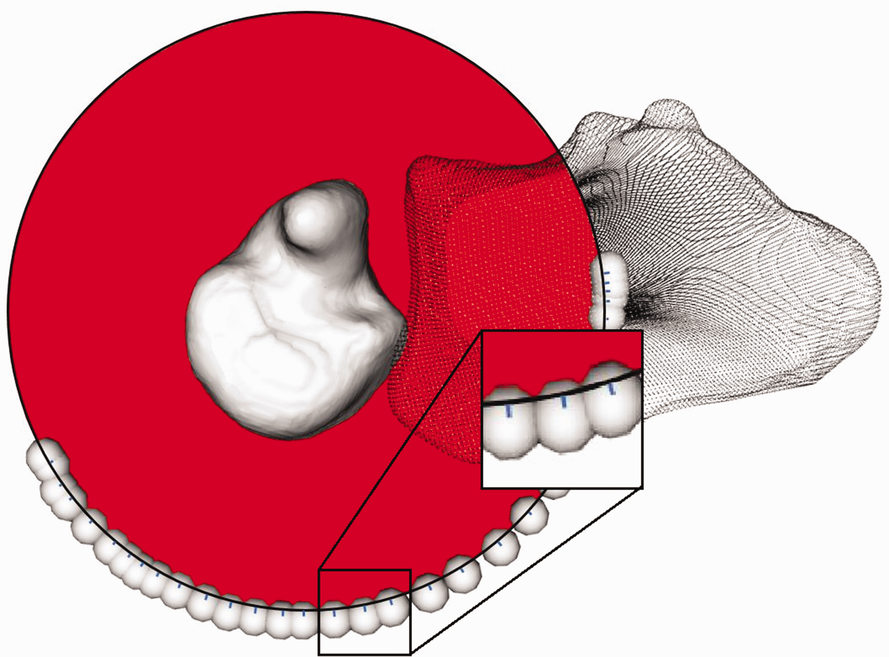
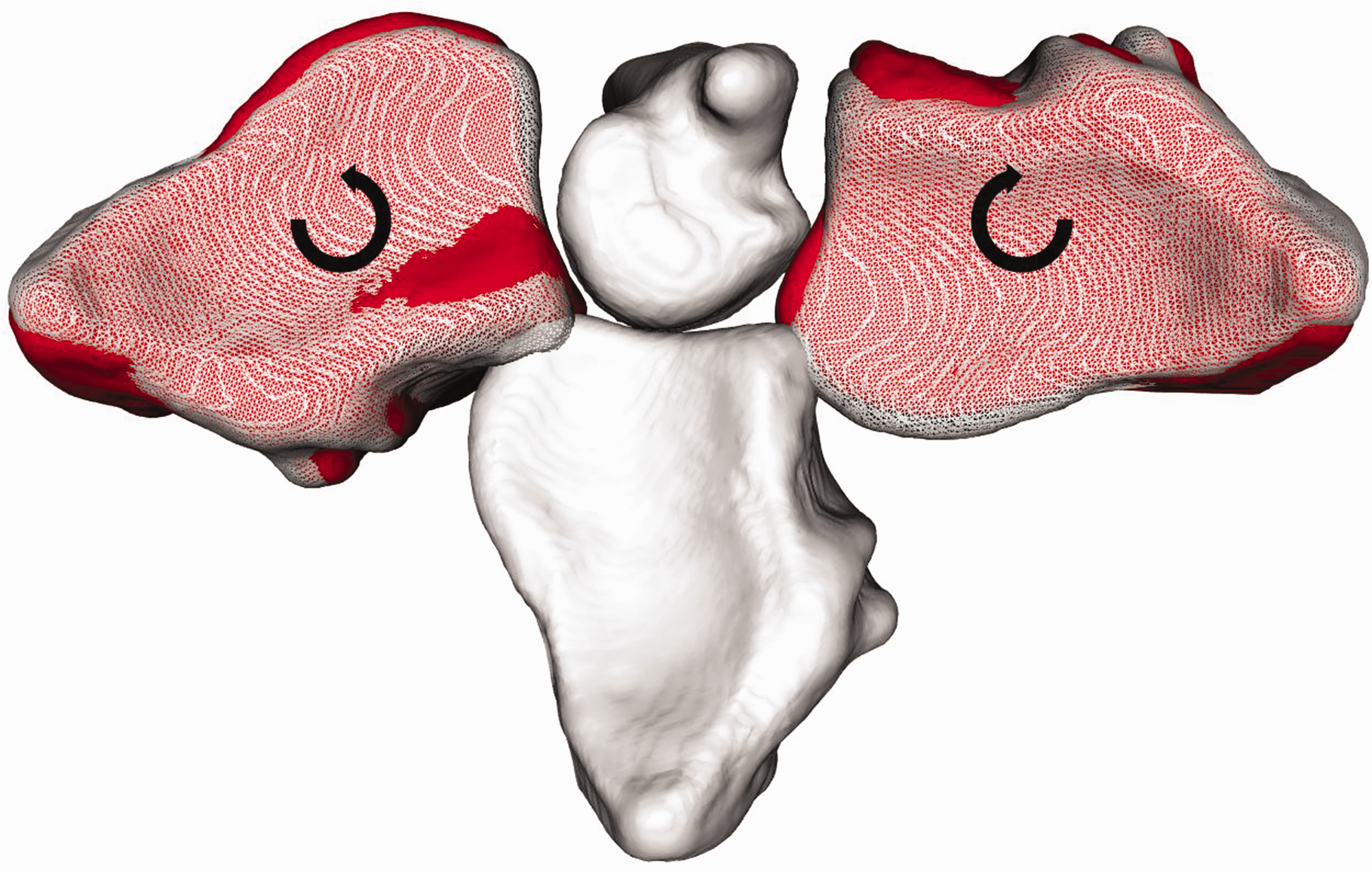
The result of fitting a circle (red) through the centroid locations (spheres) of a distal bone segment in 33 positions between full pronation and full supination. The distances of the individual centroids to the circle fit are marked by the blue lines at the edge of the black circle (enhanced in the zoomed window).
Circle fit performance when fitting using a different number of points. The root mean square error (RMSE) columns present the methodological error of the fit (Figure 4). The last two columns describe the mean Euclidean distance between the intersections of the best possible circle fit rotation axis (33 points) and the circle fit axis with fewer points (defined in the first column) at a distal and proximal intersection plane (Figure 3). The intersections at the distal plane are visualized in Figure 5. All values are given as mean (SD) in millimetres.
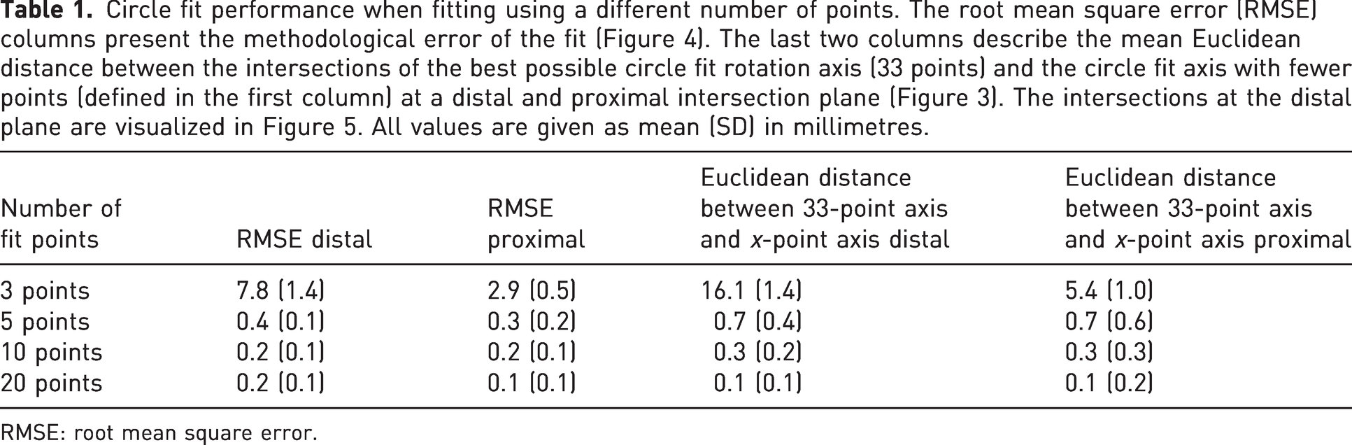
RMSE: root mean square error.
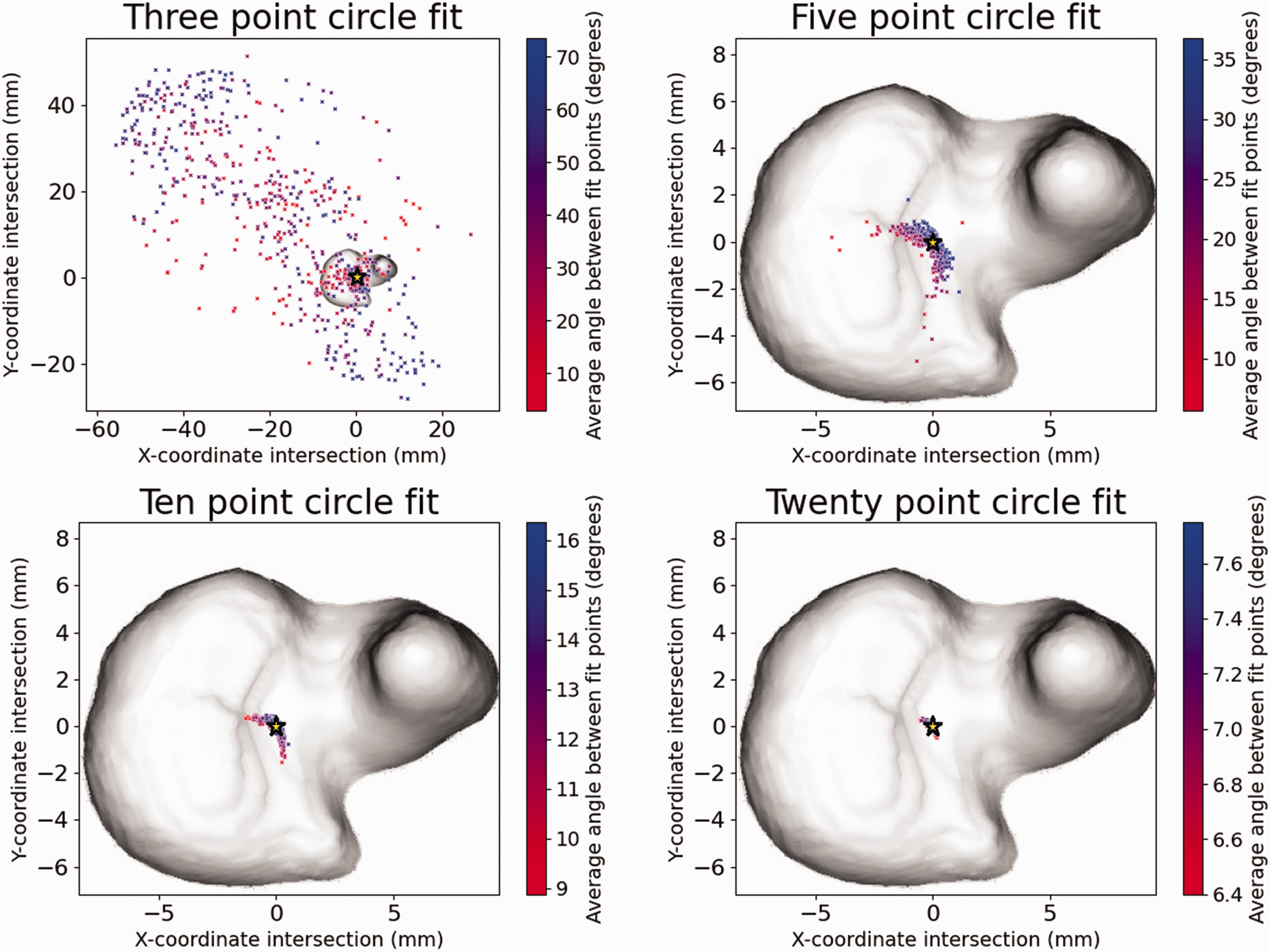
Circle fit centre of rotation when using three, five, ten or 20 fit points. The colour gradient of each centre of rotation denotes the mean angle between the sampled fit points. A higher angle means a larger portion of the range of movement was considered, resulting in an improved fit. The yellow star denotes the centre of rotation of the 33-point circle fit.
Comparing FHA analysis and the circle fit approach
The mean angle between the forearm rotation axis obtained using the FHA and circle-fit approach was 1.4° (SD 1.3°). The mean Euclidean distances between all possible FHAs and the 33-point circle fit rotation axis at the distal- and proximal intersection plane (Figure 3) were 2.4 mm (SD 1.0) and 3.2 mm (SD 3.0), respectively. A visual representation of this error for one of the participants is given in Figure 6.
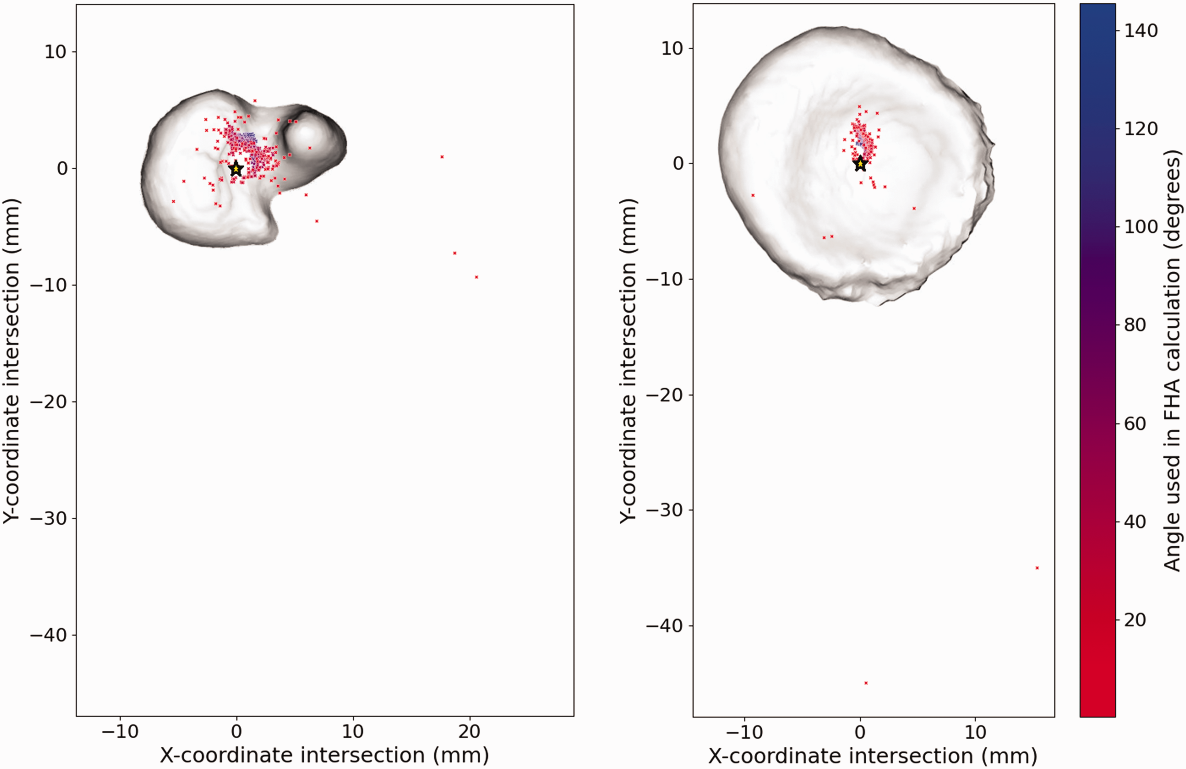
Finite helical axes (FHA) (colour gradient) and 33-point circle fit axis (yellow star) intersections at the distal (left) and proximal (right) plane. FHAs with a blue colour were based on a higher angular displacement and should therefore be more accurate.
Rotation of the radius around the radial axis
The mean rotation of the radius around the radial axis was 7.2° when rotating the forearm from a supinated to a pronated position (Figure 7). On average, the radius was rotated minus 4.1° (SD 1.7°) around the radial axis in the supinated position and 3.2° (SD 2.1°) in the pronated position. An overview of the rotation around the radial axis in relation to the rotation of the forearm is given in Figure 8.
Rotation around radial axis. The white solid radius depicts the neutral position. In red the radius is in the fully supinated and pronated positions. The white translucent radii depict the result of solely rotating the radius around the forearm axis of rotation with an angle equal to the range of movement from neutral to fully supinated and pronated. The difference between the red and the translucent radius visualizes the additional rotation around the radial axis which is opposite to the direction of forearm rotation.
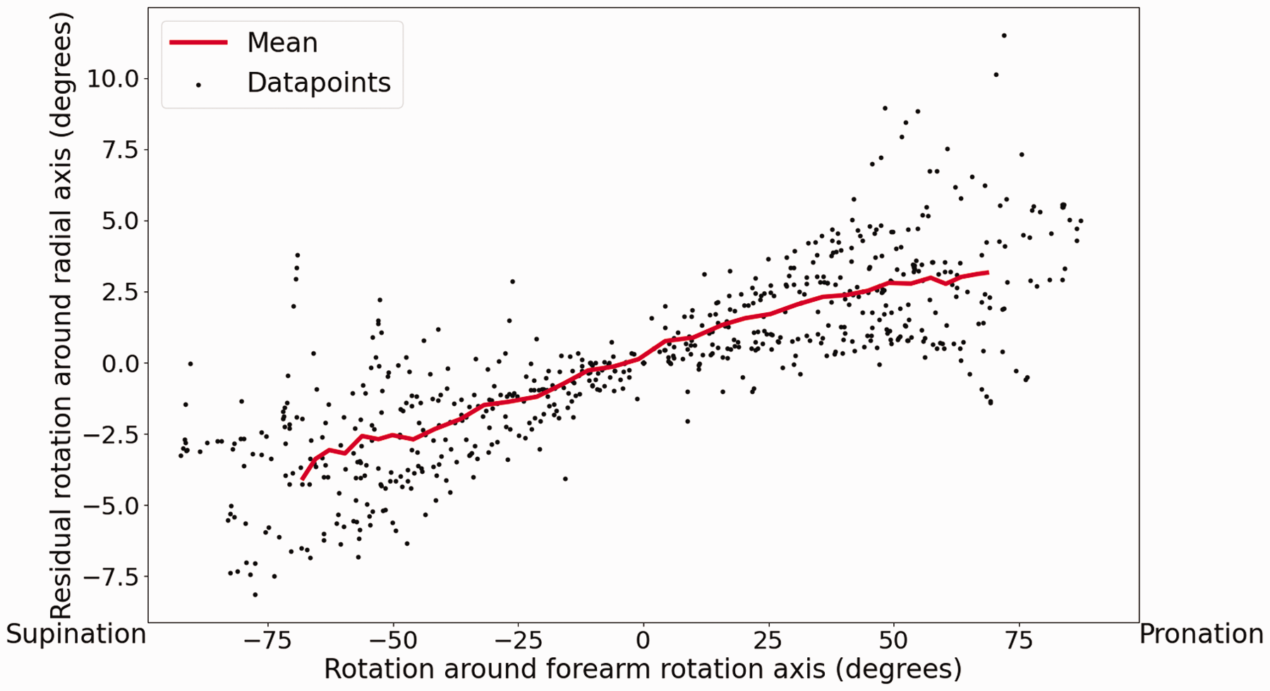
Angle of the rotation around the radial axis with respect to the forearm position. Data points from all ten volunteers (grey) and the mean (red).
Translation along the forearm rotation axis and the ulnar axis
The mean translation of the sigmoid notch of the radius along the ulnar axis was 2.6 mm (SD 0.8). The mean translation of the sigmoid notch of the radius along the forearm rotation axis was 0.6 mm (SD 0.9).
Discussion
There has been no consensus on the nature of forearm rotation. In particular, the position and orientation of the forearm rotation axis are often debated. This study presented a new approach in which 4-D-CT position data and a circle fit was used to find the axis of rotation rather than calculating the FHA based on a limited number of scan positions. For angular displacements larger than 10°, the error of the FHA analysis is similar to that of the circle fit (Ancillao, 2022; Spoor, 1984; Tay et al., 2008). For smaller angular displacements, which are common for current dynamic imaging studies (Leng et al., 2011; Morishige et al., 2022; Seah et al., 2021), the circle fit outperforms the FHA analysis.
The combination of 4-D-CT and the circle fit method to determine the forearm rotation axis results in a small methodological error. This small error indicates that the motion pattern of rotation of the radius around the forearm rotation axis is near-circular and as a result the forearm rotation axis itself remains in an approximately fixed position and orientation with respect to the ulna. The fixed nature of the rotation axis contrasts with the findings of two studies that reported different positions of the rotation axis when different portions of the ROM were used for calculations (Matsuki et al., 2010; Tay et al., 2010). We believe that the notion of a dynamic rotation axis is related to the use of the FHA analysis, since the same movement pattern of the rotation axis was found in this study when using the FHA analysis. As the studies reporting the dynamic rotation axis both use a large angular displacement to calculate their FHAs, the shift of the rotation axis is caused by something other than a large methodological error. The reported movement of the forearm rotation axis may be explained by the fact that the FHA analysis combines all movements of the radius into one translation and rotation around the FHA, whereas this study showed that the radius moves with respect to three different axes (Figure 1).
In our study we observed rotation of the radius around its own longitudinal principal axis of inertia, the radial axis. This could be linked to the sliding motion within the DRUJ as reported previously (Chen and Tang, 2013; King et al., 1986; Matsuki et al., 2010; Shakoor et al., 2019), since the outward rotation around the radial axis, combined with the inward rotation around the forearm rotation axis, suggests the sliding motion of the sigmoid notch (Figure 9). The behaviour may be linked to the tensioning of the triangular fibrocartilage complex (TFCC), in particular the deep radioulnar ligaments (Yamazaki et al., 2021), which increases linearly as the radius reaches a more pronated or supinated position.
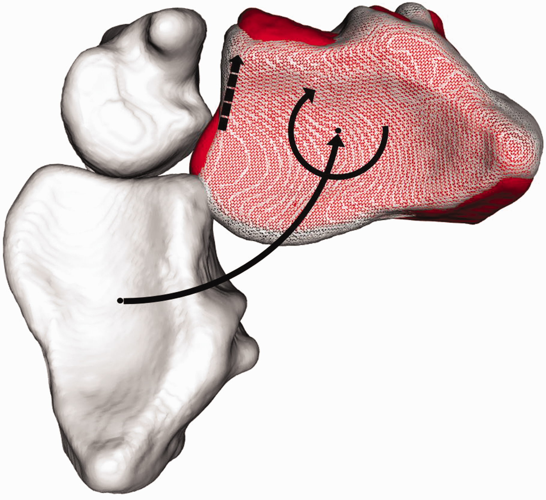
Possible explanation for the sliding phenomenon. The opposed rotations around the forearm rotation axis and the radial axis cause an effect from which it seems that the radius translates dorsally at the end of the range of motion.
Our results show a translation of the radius along the ulnar axis of 2.6 mm, which is slightly larger than other reports about changes in ulnar variance (Jung et al., 2001; Yeh et al., 2001). The ulnar variance is prone to change with differing forearm positions, elbow positions and grips (Fu et al., 2009; Jung et al., 2001; Yeh et al., 2001). These studies have measured ulnar variance in the pronated, neutral and supinated positions. They may therefore have missed the highest point of the radius; this point was found to be at a mean of 31% (SD 15) of the ROM in our study. This may explain the ulnar variance being smaller in earlier studies. If we look at our data set in the same way as in the other studies, the translation would be 1.5 mm (SD 0.7). We had expected that the translation along the ulnar axis would be caused solely by tilting of the radius across the ulna. However, the translation along the forearm rotation axis, possibly caused by laxity within the tendons at the PRUJ, disproved this.
In this study each forearm rotation started from a supinated position and moved to fully pronated position. This may be considered a limitation since moving in the opposite direction may have shown a different motion pattern, because different muscles are responsible for producing supination and pronation. However, all the other parameters related to forearm kinematics, such as bone geometry and the relevant ligament structures, are the same. Therefore, it was assumed to be unlikely that the motion patterns would differ greatly. Furthermore, we tested forearm kinematics only in a near-flexed elbow position. However, elbow flexion has been found to influence forearm kinematics with different elbow positions leading to significant changes in the range of forearm rotation and the location of the distal centre of rotation (Fu et al., 2009). The change in ROM is unlikely to have a large effect on forearm kinematics. The change in location of the distal centre of rotation does, however, affect forearm kinematics. Fu et al. (2009) used a similar circle fit method with five fit points to determine the distal centre of rotation. However, they did not report the methodological error, which we found to be 0.7 mm (SD 0.4). The reported largest shift of the distal centre of rotation reported by Fu et al. was 1.5 mm (SD 1.4) to 0.5 mm (SD 1.0), which could largely be attributable to the methodological error. The remaining translation of the centre of rotation is likely to be insignificant.
In this study it has been shown that the radius rotates around the ulna in a near-circular fashion. Apparent movement of the forearm rotation axis can be explained by the limitation related to FHA analysis. It has also been shown that the radius rotates around the radial axis throughout the ROM. Finally, it has been shown that the distal radius translates along the forearm rotation axis and along the ulnar axis during forearm rotation. These findings may be of value in the diagnosis of forearm pathology and may help in the design of new DRUJ implants to restore forearm motion.
Footnotes
Declaration of conflicting interests
The authors declare no potential conflicts of interest with respect to the research, authorship, and/or publication of this article.
Funding
The authors disclosed receipt of the following financial support for the research, authorship, and/or publication of this article: this work was supported by Eurostars [grant number 12885].
Ethical approval
Ethical approval for this study was obtained from the medical ethical committee of the Amsterdam UMC (Location AMC) (study ID: B2018_143).
Informed consent
Written informed consent was obtained from all subjects before the study.