
Abstract
The present work investigated the wear behaviour of powder metallurgy-processed ZrO2 (10 wt.%) reinforced Fe-based metal matrix composite under dry sliding conditions. The friction and wear properties were evaluated under varying loads and sliding speeds ranging from 5 to 10 N, and 0.75 to 1.25 m/s, respectively. The wear tests were performed against a counter face of EN31 steel (HRC 60) employing pin-on-disc tribometer under room temperature. Microstructural examination of the composite by field-emission scanning electron microscopy (FE-SEM), equipped with energy dispersive spectroscopy (EDS), displayed the presence as well as a homogeneous dispersion of reinforcement phase into the matrix. At a particular load and sliding speed, transition behaviour was observed in the coefficient of friction, whereas wear rate increased with increasing load and sliding speed. The analysis of worn surface indicated that the adhesive wear was dominant at relatively high operating conditions, while abrasive wear remained operative at lower load and sliding speed.
Introduction
Bearings are employed to transmit motion and reduce friction between the moving components of machine elements such as gearbox, connecting rod, crankshaft, etc. In order to attain higher reliability of the mechanical system, efficient functioning of the bearing is needed. Therefore, for bearing material it is desired to have excellent mechanical and wear resistance properties. 1 Metal matrix composites are considered as a suitable candidate for the aforesaid concern. Metal matrix composite consists of two phases: matrix and reinforcement phase. The uniform distribution of reinforcement phase into the matrix is one of the alternatives for obtaining the tailor-made properties. 2 For the development of metal matrix composites, various methods have been proposed namely, stir casting, chemical vapour deposition, spray deposition, powder metallurgy (P/M), etc. 3 Nowadays powder metallurgy is more preferred over other techniques on account of its advantages, that is, homogeneous dispersion of reinforcements, and enhanced bonding between matrix and reinforcement. 4 In various investigations, metals such as Al, Cu, Ti, etc., were taken as a matrix phase for the development of metal matrix composites owing to their enhanced corrosion resistance and lower density. 5 However, inferior strength and hardness limit their scope as a suitable matrix material for emerging tribological applications. Recently, iron as a matrix has shown potential as a future alternative due to its superior physical and mechanical properties as compared to other metals. 6 As far as its tribological properties are concerned, various reinforcements in the form of ceramic particulates have been incorporated into it to realise its maximum potential.
In this direction, researchers have reported the mechanical and wear properties of various ceramic-reinforced Fe-based metal matrix composites processed using P/M.7–10 Gupta et al. 11 observed that wear rate of Fe-Al2O3 metal matrix composites was dependent on the sintering temperature and time. Adhesive wear was found to be dominant at lower load, while abrasive wear was instrumental at higher load. In another study, Ramesh et al. 12 explored tribological properties of Fe-SiC composites and reported improved hardness and wear resistance as a result of SiC (up to 7 wt.%) addition. In contrast, coefficient of friction (COF) was found to increase under similar conditions of sliding wear. Moreover, Parveez et al. 6 observed reduced COF and wear rate of Fe-Cu-Sn-based composites with the addition of nano ZrO2 and MoS2. Conversely, microhardness increased with the ZrO2 reinforcement. In addition, Shamsuddin et al. 13 investigated the microstructure, mechanical and wear properties of Al2O3-reinforced Fe-Cr-based composites. Improved Vickers microhardness and wear resistance were found for 20 wt.% Al2O3 addition, and beyond that concentration of reinforcement mechanical properties deteriorated. In a similar vein, Zhang et al. 14 found the formation of Fe3W3C phase during sintering and analysed increased hardness and wear resistance as an outcome of WC addition in Fe-based composite.
It has been observed from literature review that addition of different hard ceramics in the Fe-based composites manifested into a harder phase and consequently improved the mechanical and tribological properties. However, despite the unique properties of ZrO2 as a reinforcement phase, 15 its feasibility both as a bearing material and how it responds at different operating conditions of normal load and sliding speed (tribological properties) is not yet fully explored. The present investigation is an attempt to explore the friction and wear properties of ZrO2 (10 wt.%) reinforced Fe-based metal matrix composite under dry sliding conditions. The wear tests were carried out by varying the normal loads and sliding speeds. The wear mechanisms were explained on the basis of worn surface morphology.
Experimental details
In the investigation, powders of electrolytic iron (Fe), particle size ranging 250–300 µm with 99.5% purity and zirconium dioxide (ZrO2) with particle size ranging 0.8–7 µm having 99.8% purity are used to prepare the metal matrix composite deploying powder metallurgy. Both the powders have been supplied by Loba Chemie Pvt. Ltd (India). Figure 1 depicts the morphology of ZrO2 powder which is nearly spherical in shape. To begin with, Fe powder was mixed with 10 wt.% ZrO2 and the mixture was subjected to ball milling in dry conditions by employing zirconia balls. Ball milling was carried out for 2 h and the ball-to-powder weight ratio was 1:2. After the ball milling process, the powders were used to make green specimens by compacting the powders. Hydraulic press was used for compacting the powders at a load of 7 ton. Further, sintering was carried out at a temperature of 1100 °C for 1 h in an inert atmosphere. A nomenclature 10ZrFe1100(1) was used to denote the sintering temperature and time of the sintered specimen.
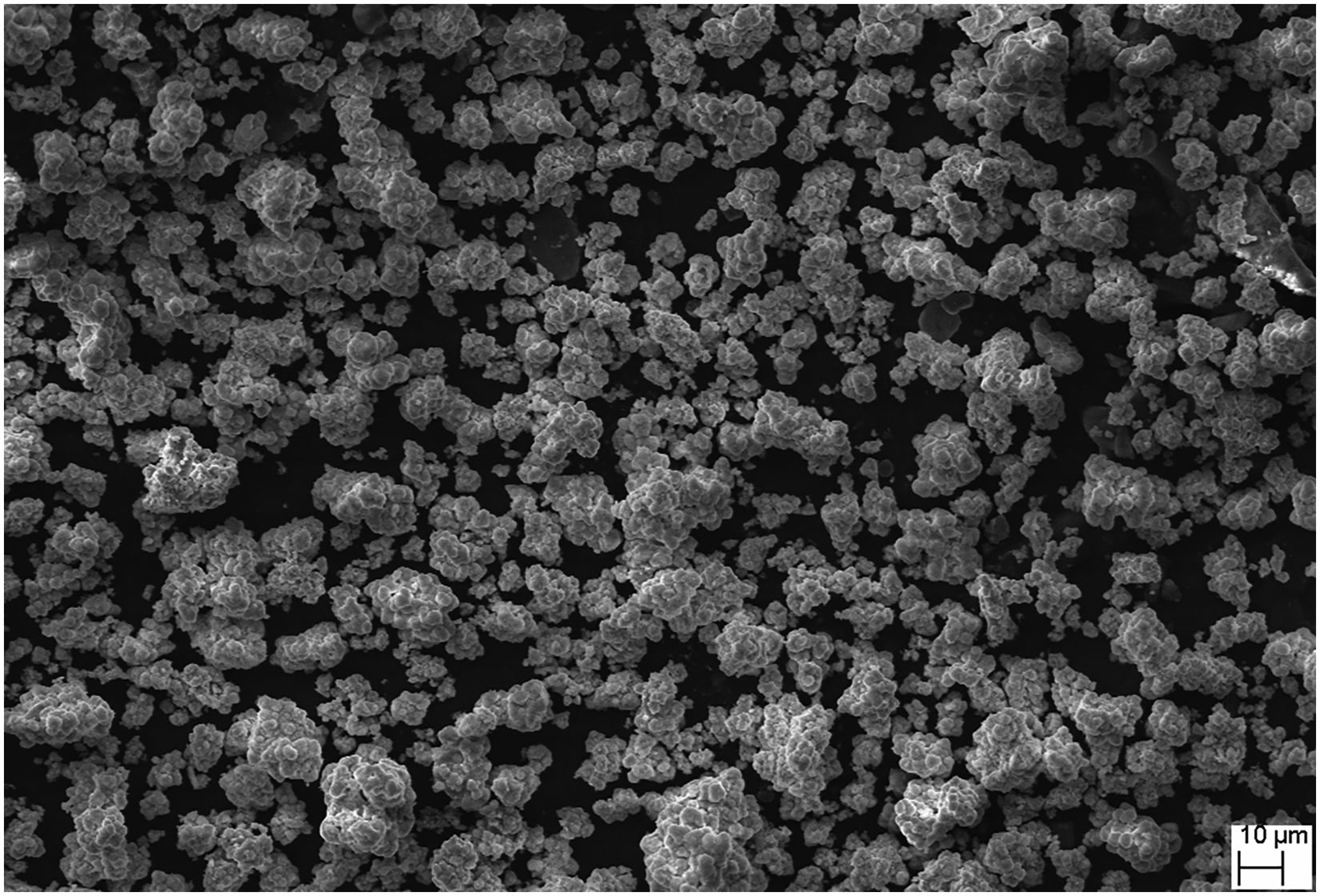
Morphology of ZrO2 powder.
Further, thorough polishing of the specimen was performed using emery papers of different grades (1/0, 2/0, 3/0 and 4/0) followed by polishing using diamond paste as well as etching with pure HCl. The microstructure was analysed using field-emission scanning electron microscopy (FE-SEM) integrated with energy dispersive spectroscopy (EDS), Zeiss Gemini SEM 450. Density of the sintered specimen was calculated using height and radius and hardness was measured by Rockwell hardness tester (H scale). 16
Dry sliding wear properties of 10ZrFe1100(1) composite were tested as per ASTM G99–05 standard deploying pin-on-disc tribometer. In the tribometer, the counter face disk is formed of EN31 steel with hardness of 60 HRC. All the tests were executed in an ambient atmosphere (temperature: 30–40°C; relative humidity: 40–50%). Prior to wear measurement, the rotating disc (counter face) was thoroughly cleaned by acetone and test specimens were grounded with 800-grit SiC paper. The friction and wear measurements were performed at various normal loads (5, 7.5 and 10 N) and sliding speeds (0.75, 1 and 1.25 m/s). Total sliding distance during investigation remained 600 m. Following every experiment, the difference in weight loss of the specimen was calculated by a weighing machine having an accuracy of 0.0001 g. Volume loss of the specimen was obtained by dividing the weight loss of the specimen with its density. Frictional force was recorded by using the control panel equipped with the tribometer. COF was further assessed by dividing the frictional force by the applied load. For a particular condition, every experiment was repeated three times and their mean value of the volume loss was estimated. Further, computed volume loss was used for the estimation of wear rate. The common formula used to compute the wear rate is as follows:
17

The worn morphology is treated by FE-SEM and EDS to understand the concept and nature of the wear behaviour.
Results and discussion
Microstructural characterisation
FE-SEM is one of the highly sophisticated techniques employed to capture the high-resolution micrograph of the materials. It is performed in a highly vacuum condition to avoid the disruption of the electron beam as well as emitted secondary and backscattered electrons were utilised for image capturing. Further analysis was performed using EDS. It is an X-ray technique used to identify the elemental composition of the material. Figure 2(a) and (b) presents the high magnification FE-SEM micrograph (5000×) of 10ZrFe1100(1) composite with its corresponding EDS pattern. Micrograph depicts the presence of a reinforcing phase in the matrix (white in colour).
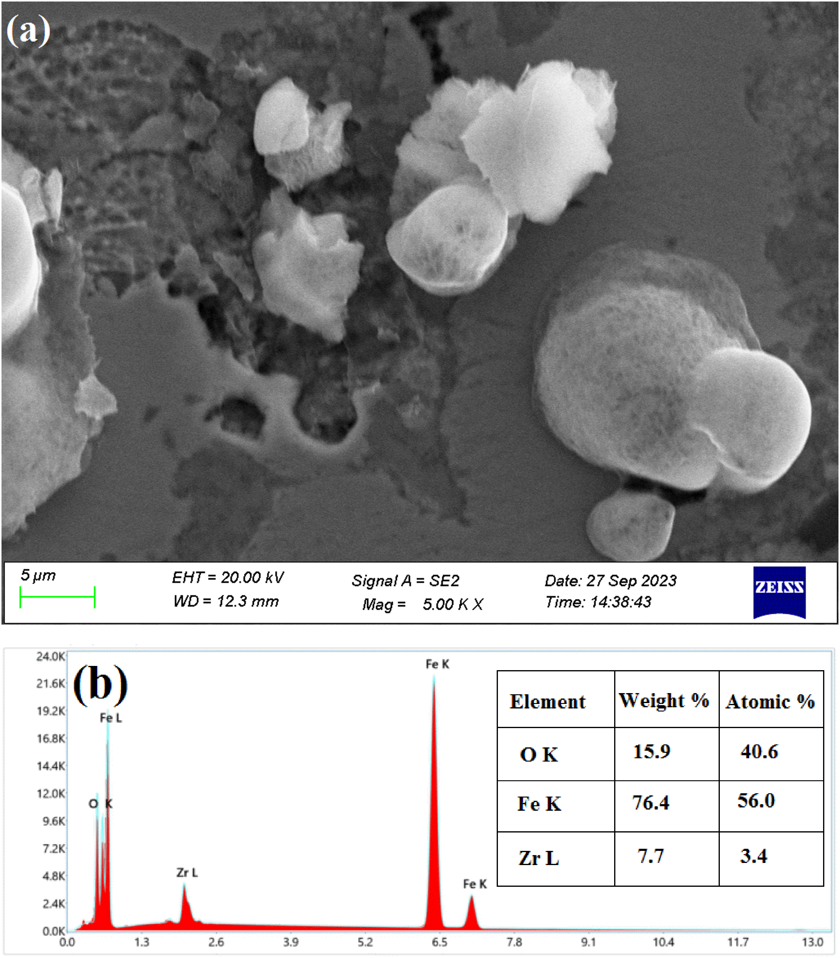
(a) High magnification FE-SEM micrograph and (b) EDS pattern of 10ZrFe1100(1).
The presence of the reinforcing phase was analysed through the EDS pattern. The EDS pattern shows the existence of the highest peak of matrix (Fe) along with the reinforcement phase with its corresponding atomic and weight percentage. The compositional analysis depicted in the inset of Figure 2(b) confirmed the presence of matrix and reinforcement phase in the specimen. Moreover, traces of oxygen can be observed in the pattern that would have come due to sample polishing before the FE-SEM was captured. In addition, microstructural examination was done using overlay field emission micrograph and elemental mapping analysis as depicted in Figure 3(a)–(e).
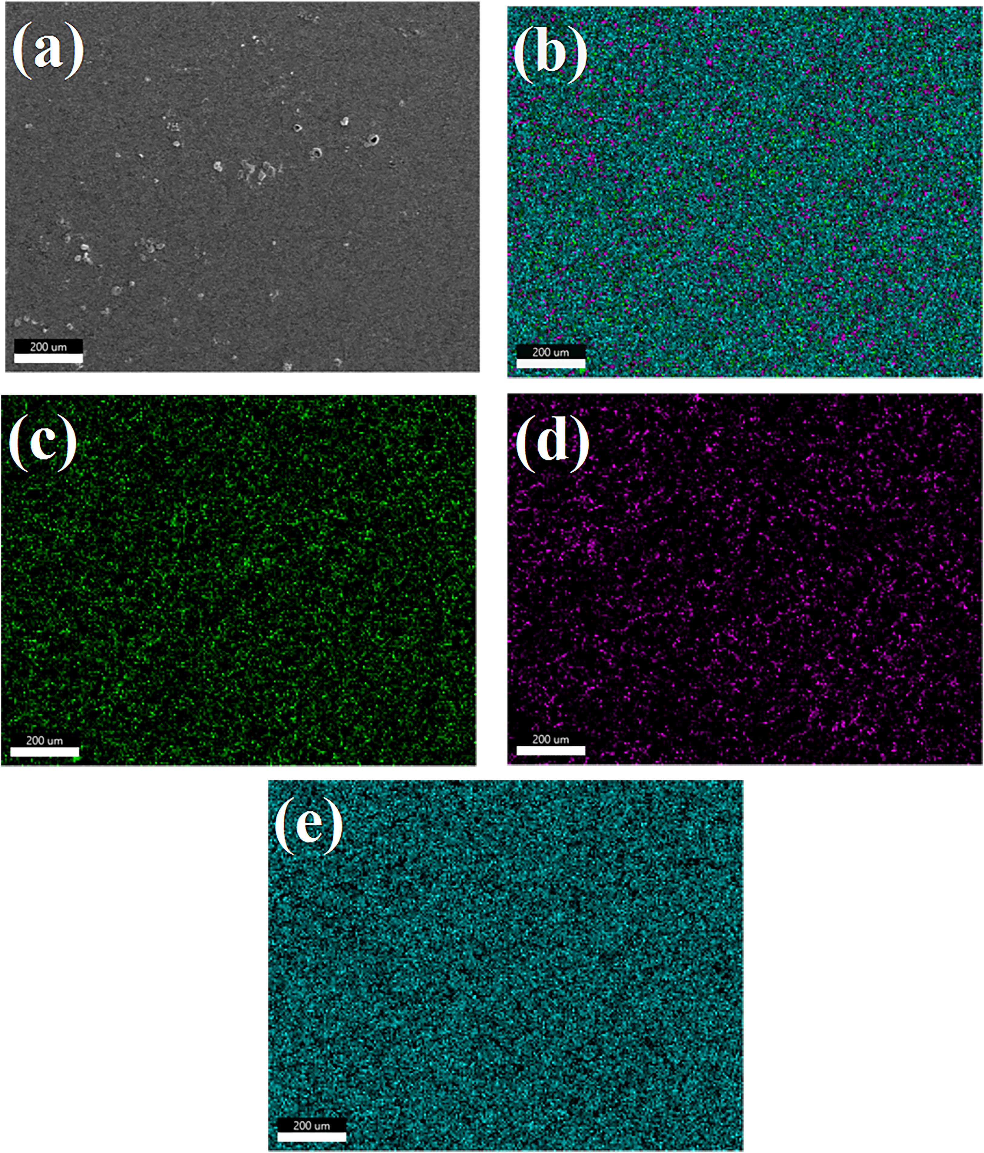
(a) FE-SEM image of composite, (b) overlay field emission micrograph and elemental mapping analysis of (c) O, (d) Zr and (e) Fe.
Figure 3(a) illustrates the FE-SEM image of the composite used for mapping. The respective color coding of the element can be seen in Figure 3(c)–(e). Overlay mapping (Figure 3(b)) is expected to assist in identifying the presence of participating elements in the composite. Density of the sintered specimen is reported to be 5.4 g/cm3 and H scale hardness (HRH) as 54. 16
Friction and wear behaviour
Figure 4 depicts the variation of COF with sliding distance at the applied loads of 5, 7.5 and 10 N and constant sliding speed of 0.75 m/s for the composite 10ZrFe1100(1). Error bars have been shown in all the graphs to make them more clear in terms of reproducibility of results. One could observe that at 5 and 7.5 N loads the COF is found to increase first and beyond 400 m it has slightly decreased.
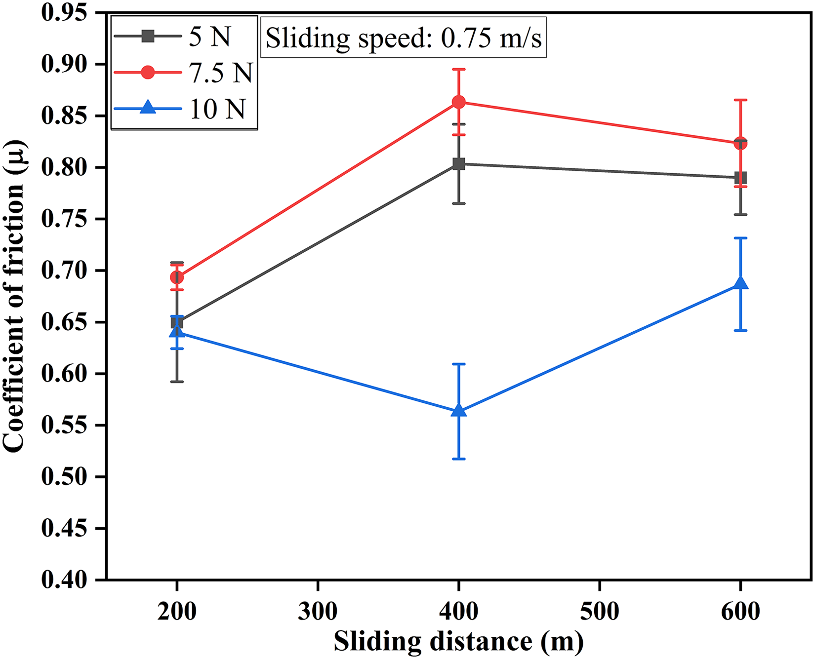
Variation of COF with sliding distance.
Whereas, at higher load (10 N) COF decreased first, and beyond 400 m it was found to increase. It is evident that there was no fixed trend for COF with sliding distance. This can be explained by the typical role played by the entrapped particles during the sliding wear, and this entrapped particle may initiate three-body abrasion. It could be a possible reason for such uncertainty in COF with sliding distance.
It can be inferred from Figure 5 that the COF shows transition behaviour at a particular normal load and sliding speed. One could observe the change of COF with sliding speed for a total sliding distance of 600 m under normal loads of 5, 7.5 and 10 N, respectively. COF was observed to increase at a load of 5 and 7.5 N as sliding speed increased from 0.75 to 1 m/s, and beyond that it showed decreasing trend. However, at 10 N load, COF increased corresponding to different sliding speeds as depicted. At a higher load, a relatively lower COF was observed for the investigated specimen.
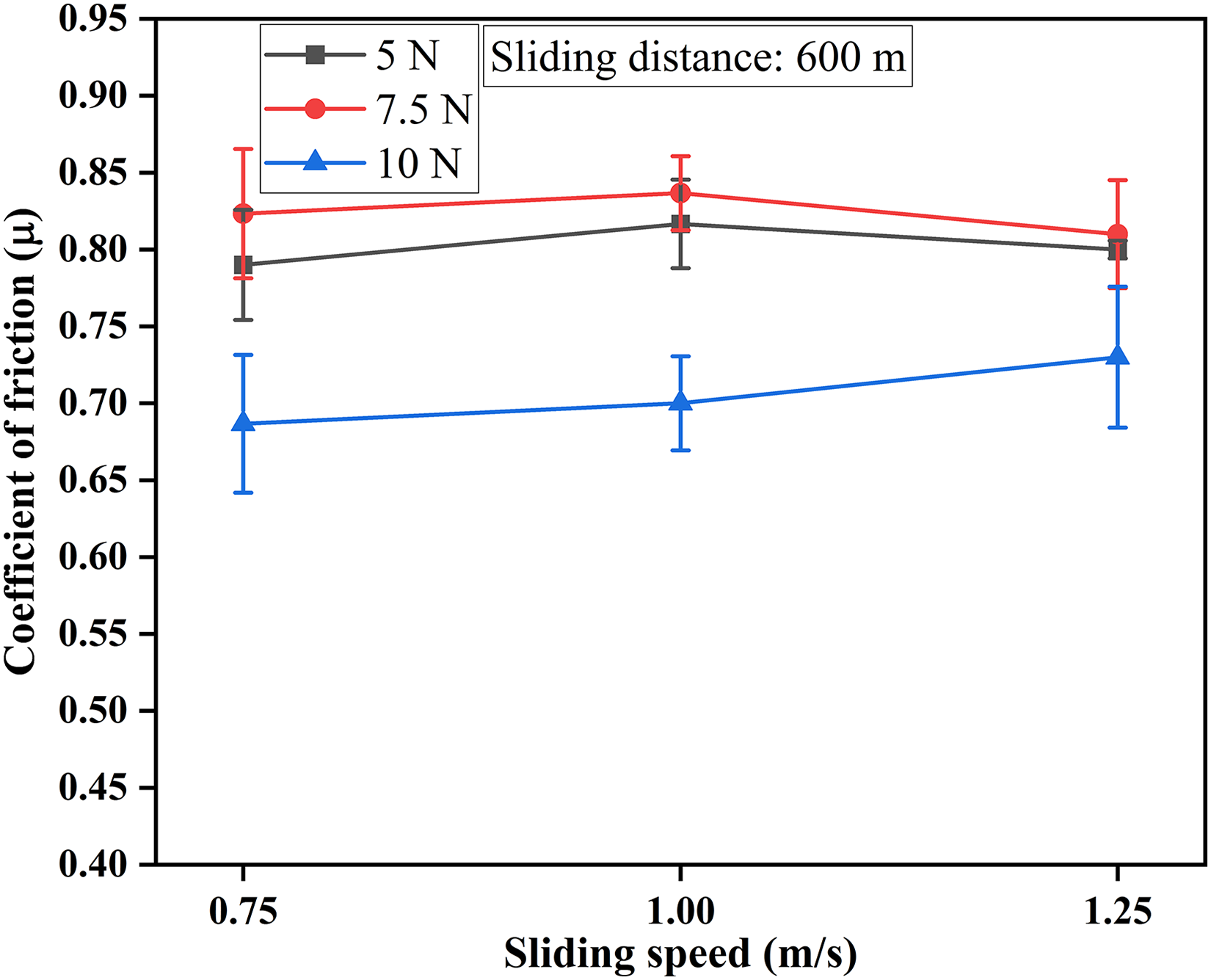
Variation of COF with sliding speed.
Figure 6(a)–(c) represents the variation of cumulative volume loss with sliding distance for 10ZrFe1100(1) composite at various loads of 5, 7.5 and 10 N and at constant sliding speeds of 0.75, 1 and 1.25 m/s, respectively. Apparently, cumulative volume loss increased almost linearly with sliding distance and it was ascertained by means of curve fitting using linear least square fitting technique. However, data points are joined point to point in Figure 6. At 10 N load, the specimen revealed maximum volume loss under all the operating conditions as shown in Figure 6(a)–(c). Whereas, the specimen demonstrated minimum volume loss at a load of 5 N under similar conditions. The result is not surprising because at higher load, contact asperities increased and it initiated the proportion of worn surface material. It can also be inferred that volume loss of the investigated specimen increased as sliding speed increased from 0.75 to 1.25 m/s. The underlying reason may be accredited to the fact that surface temperature increased with increase in sliding speed, and it initiated the softening of the surface, which further aggravated the surface damage, and consequently resulted in higher volume loss.
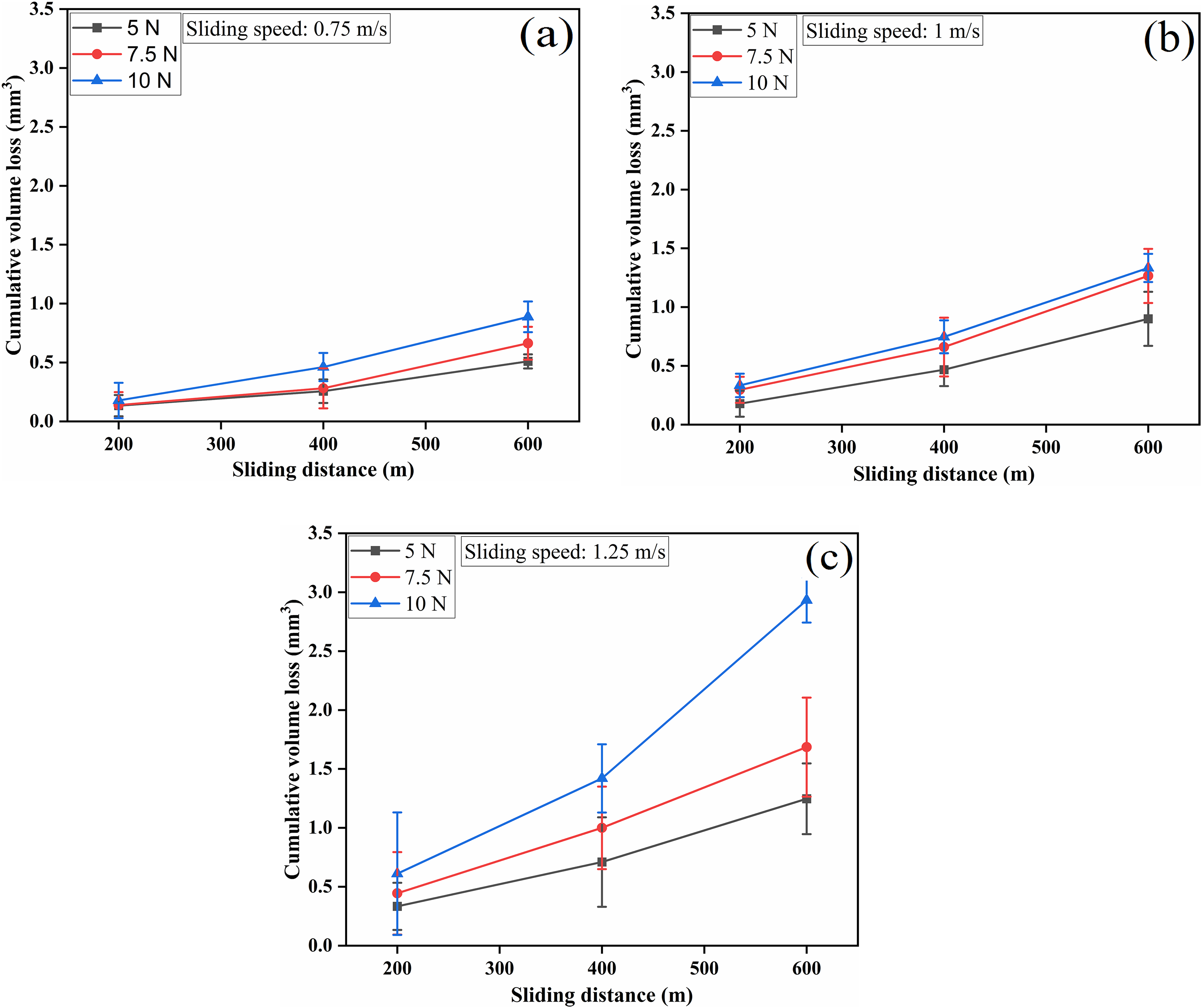
Variation of cumulative volume loss with sliding distance at sliding speeds of (a) 0.75 (b) 1 and (c) 1.25 m/s, respectively.
Outcome of process parameters, normal load and sliding speed on the wear rate of 10ZrFe1100(1) is depicted in Figure 7.
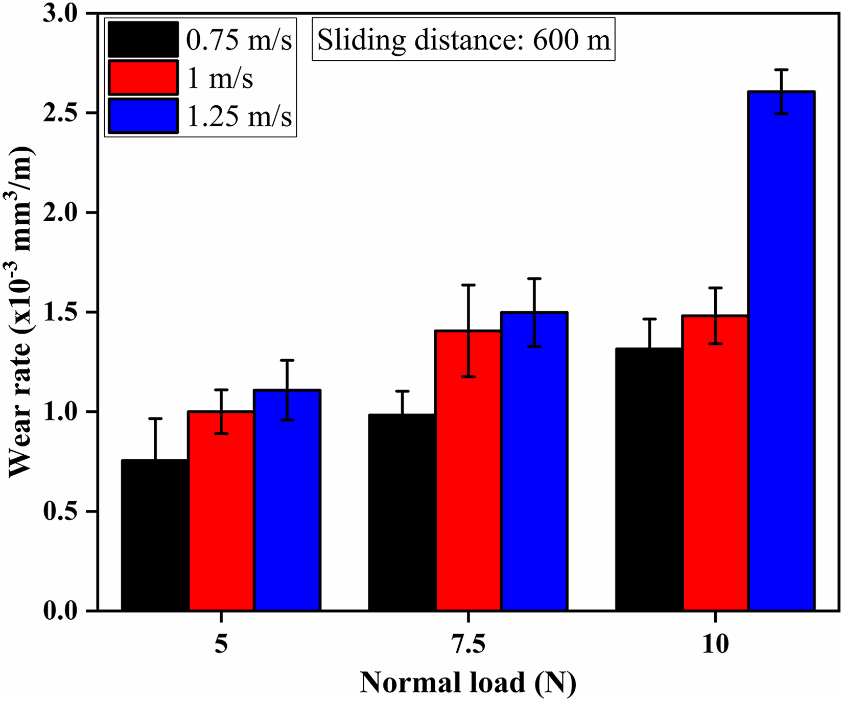
Variation of wear rate with normal load.
The total sliding distance remained 600 m for the investigated specimen. It can be observed that wear rate increases as normal load and sliding speed increase. Similar trend has equally been reported elsewhere.
18
Maximum wear rate can be observed at 10 N load, whereas minimum wear rate can be seen at 5 N load. This particular behaviour can be well explained according to Archard's equation,

Worn surface analysis
Figure 8(a)–(c) shows the worn morphology of the 10ZrFe1100(1) composite subjected to an applied load of 5 N and constant sliding speeds of 0.75, 1 and 1.25 m/s, respectively. Parallel fine grooves can be observed in Figure 8(a), which are running along the sliding direction. Micrograph 8(b) shows a bit finer grooves in the sliding direction along with little fragments of wear debris. The presence of grooves can be attributed to the abrasion caused due to the harder asperities of the counter face. The abrasion may cause dislodge of the particles from the pin material and may initiate wear debris formation. A lump of loose layer of wear debris along with fine grooves could be observed in Figure 8(c). Grooves are mostly covered by the layer of wear debris and possibly the extent of cover given by wear debris may explain the absence of wear tracks, particularly caused by the sliding process.
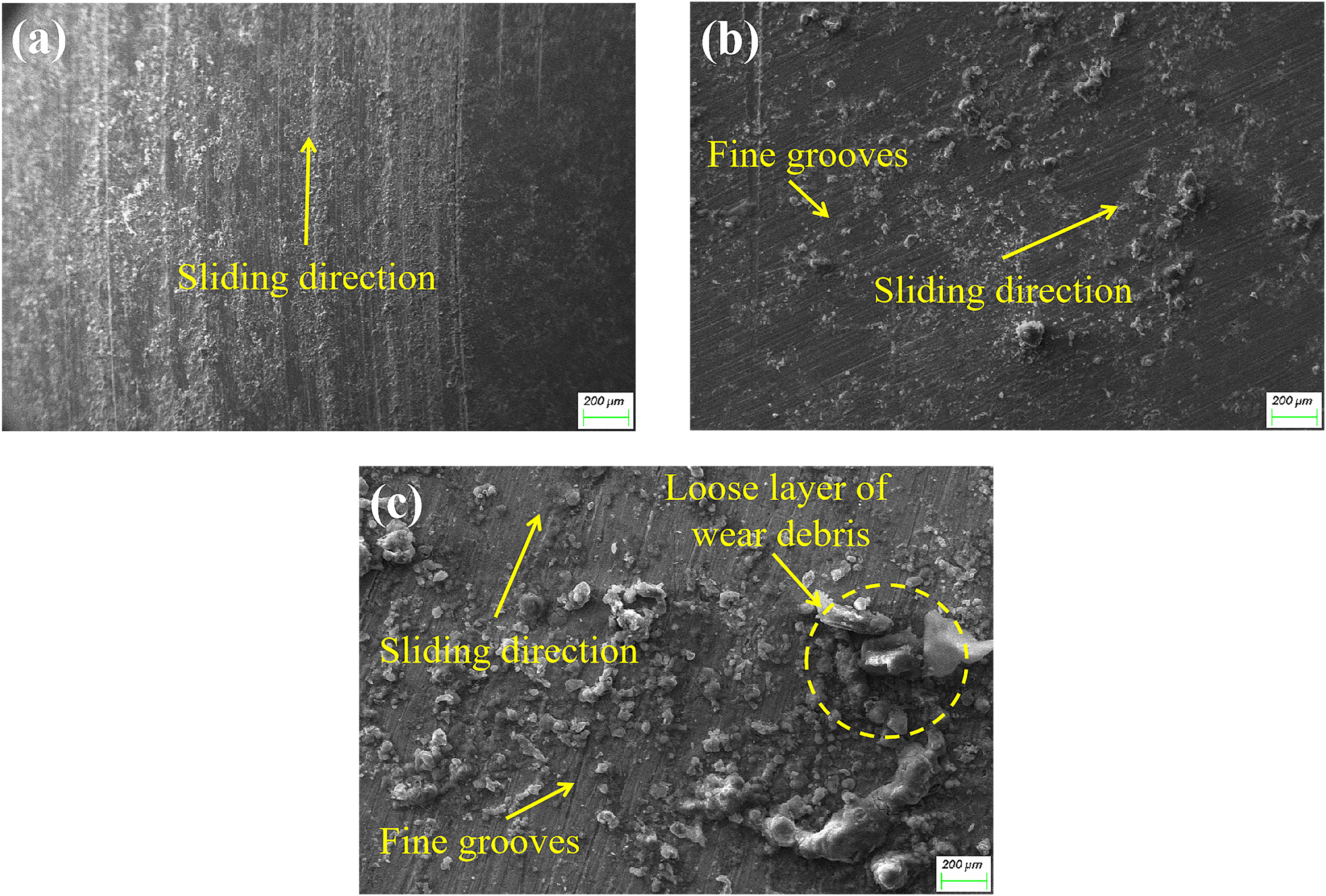
FE-SEM micrographs of worn surface of 10ZrFe1100(1) composite specimens subjected to an applied load of 5 N and constant sliding speeds of (a) 0.75, (b) 1 and (c) 1.25 m/s, respectively.
Effect of higher load (10 N) and varying sliding speeds can be well examined through worn surface analysis of 10ZrFe1100(1) composite as revealed in Figure 9(a)–(c). Micrograph 9(a) revealed the lump of wear debris and no discernible grooves can be observed. As the sliding speed increased, the wear debris formation occurred due to ploughing of the contacting asperities or due to delamination mechanism. The generated wear debris may promote three-body abrasion and may result in the formation of deep grooves along the sliding direction and some particles pulled out from the pin surface as depicted in Figure 9(b).
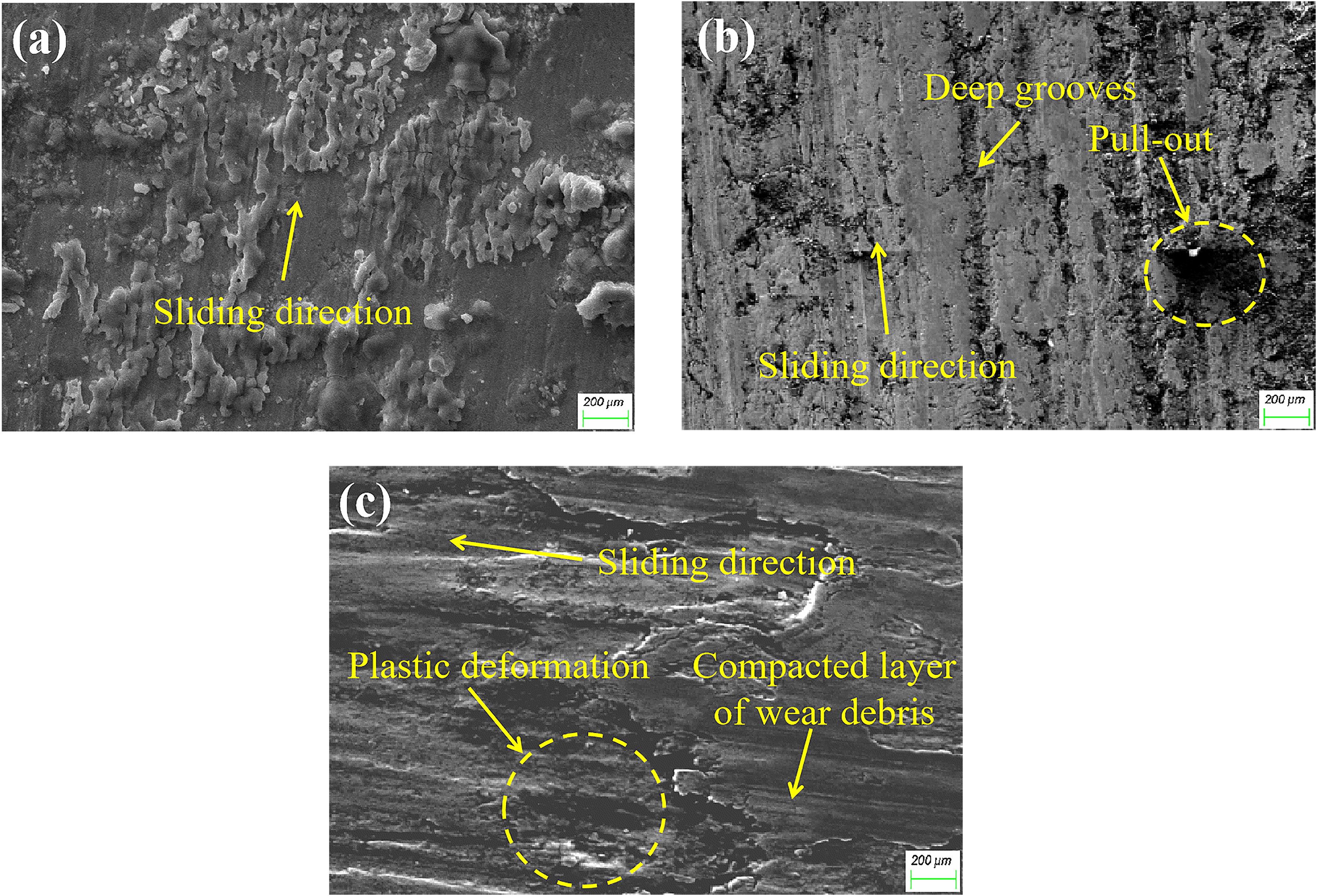
FE-SEM micrographs of worn surface of 10ZrFe1100(1) composite specimens subjected to an applied load of 10 N and constant sliding speeds of (a) 0.75, (b) 1 and (c) 1.25 m/s, respectively.
The particle pull-out may take place due to the weak bonding between the matrix and ZrO2 in spite of using powder metallurgy route for processing. Furthermore, research is needed to explore the problem related to bonding. The pulled-out particles are responsible for abrasive wear until they are loosed. Figure 9(a) and (b) substantiates that the wear mechanism is mostly abrasive in this case as already explained earlier. As the load and sliding speed increased, the pulled-out particle (during sliding wear) may get mixed with the oxide and other metallic particles transferred from the counter face and formed a transfer layer at the interface, which might have further converted into compacted layer due to frictional heating (Figure 9(c)). The compacted layer of wear debris gets attached with the substrate and it inhibits the direct metal-to-metal contact. This compacted layer of wear debris may be accountable for the reduced COF at higher sliding conditions.20–22 It sounds reasonable because the COF at 10 N load is lower as compared to 5 and 7.5 N loads as depicted in Figure 5. Within the micrograph presented in Figure 9(c), a region of plastic deformation could be observed. The reason for this is supposed to be the formation of high heat at the contacting surfaces. The high temperature at the interfaces may lead to delamination and plastic deformation to occur. 23 The plastic deformation expedites the rate of material removal and thus the wear rate of the composite increases. This may confirm the result presented in Figure 7. It can be outlined that the micrographs 9(a, b) support that wear mechanism is primarily abrasive in nature at lower load and sliding speed. However, the adhesive wear mechanism is dominant at higher load and sliding speed as illustrated in Figure 9(c). Figure 10 reveals a typical EDS analysis of the worn surface morphology of 10ZrFe1100(1). The spectra show the oxygen peak that points out that oxidation may have occurred during the sliding process.
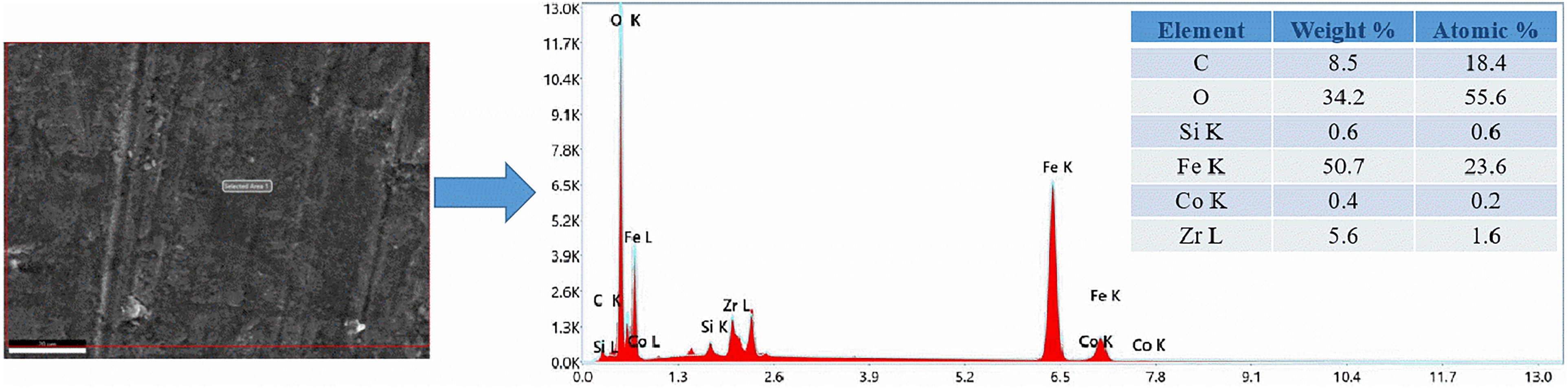
EDS analysis of 10ZrFe1100(1) composite.
Conclusions
The following conclusions are drawn from the present investigation:
Composite was successfully developed using powder metallurgy. Microstructural examination revealed the presence and homogeneous dispersion of the reinforcement phase into the matrix. COF shows transition behaviour at loads of 5 and 7.5 N. It increased first as sliding speed increased from 0.75 to 1 m/s and beyond that it decreased. However, the COF increased at a load of 10 N corresponding to different sliding speeds. Wear rate of composite increased with increase in normal load and sliding speed. It could be confirmed through worn surface analysis that at higher operating conditions adhesive wear is dominant, while abrasive wear remained operative at lower load and sliding speed.
Footnotes
Acknowledgements
The corresponding author hereby expresses his sincere thanks to Central Research Facilities (CRF), KIIT Deemed to be University, Bhubaneswar 751024 (India) for the characterisation facilities relating to this work.
Declaration of conflicting interests
The authors declared no potential conflicts of interest with respect to the research, authorship, and/or publication of this article.
Funding
The authors received no financial support for the research, authorship, and/or publication of this article.