
Abstract
In this study, the impact of substrate dilution on the microstructure and tribological properties of tungsten inert gas (TIG)-deposited self-lubricating claddings was investigated. The dilution of Ti content on cladding increased as the TIG current increased, and the microhardness of the cladding decreased. The content of intermetallic phases such as TiNi and TiC increased with the increase in TIG current. The tribological studies revealed that coating dilution at higher TIG currents has prominent effects on wear behaviour at elevated temperatures. In both clads, the percentage decrease in hardness from higher TIG current to lower TIG current was noted as 31%. The higher dilution of Ti content in the cladding was found to be beneficial in tribological studies performed, especially at higher temperatures (≥400). Also, solid lubricants such as MoS2 and BaF2 encapsulation in the nickel alloy were found to be beneficial at both low and high temperatures.
1 Introduction
Titanium alloys are used more frequently in the aerospace, structural, and automotive fields due to their desirable properties, which include a high strength-to-weight ratio, low modulus, good corrosion resistance, and superior biocompatibility. Grade 5 titanium alloy Ti–6Al–4V is the most commonly used titanium alloy in all industries.1–5 However, titanium alloys primarily fail due to their lower wear rate when used in sliding environments, which leads to a need for improvement in the titanium alloy's surface characteristics. Many studies primarily aim to improve the surface characteristics of titanium alloys to reduce wear and friction.6,7 Several methods have been used to improve the surface characteristics of titanium and its alloys, including laser cladding, 8 plasma spraying, 9 high-velocity oxygen fuel, 10 carburising, 11 chemical vapour deposition, 12 physical vapour deposition, 13 ion implantation, 14 plasma transferred arc cladding, 15 and nitriding. 16 Few surface engineering techniques improve surface properties while leaving bulk properties relatively unchanged. In these studies, the substrate material is designed for greater component strength and hardness. At the same time, the coating is responsible for resistance to thermal loads, wear, and corrosion.17,18 Many engineering applications require materials with high resistance to chemical attacks and wear and the ability to perform intended functions in hostile environments and operating circumstances. The effects of adverse environmental and severe operating conditions are primarily limited to surfaces. For example, the surfaces of every engineering component are particularly prone to friction, heat, electrical, chemical, and electrochemical processes, all of which contribute to material degradation in the part during service.19,20 This deterioration, however, cannot be resolved unless the tribological and corrosion phenomena are regularly monitored.21,22 Surface alloying on the substrate has been used in some studies to achieve mixed material properties of the substrate and coatings.23–26 Coating techniques used in industries obviously improve the surface characteristics of titanium, which obviously increases wear resistance. However, some shortcomings, such as low coating density, poor adhesion, and porosity, would limit the use of thermal spraying and other thin coating methods in areas with rapid sliding movements. 27 In such cases, arc-assisted surface engineering or hard-facing techniques such as laser cladding, tungsten inert gas (TIG) cladding, plasma arc transferred cladding, etc., are considered necessary. Hard-facing techniques improve surface properties by metallurgical bonding of the coating to the substrate. Among several alloys, nickel alloy has been shown to be a better alternative for lowering wear and corrosion rates. Several researchers improved the wear characteristics of titanium alloy by fabricating layers on the surface of titanium alloy.28–32 The thickness of the deposit and the amount of heat input have the most significant influence on the properties of the hard-faced components. The heat input on the substrate surface caused the substrate material to partially melt during the deposition of the first layer of hard-facing alloy. The amount of dilution is primarily influenced by the quantity of heat applied to the surface during layer fabrication.33,34 It is critical to investigate the process equipment's process parameters. In some cases, adverse effects occur due to the substrate material's higher dilution. As a result, a systematic study of the effect of dilution on the properties of TIG-clad deposits is required. From the literature, it was observed that clads deposited with nickel alloy show exceptional tribological properties. However, coatings fail at higher temperatures due to thermal cracks. Due to highly loaded metal-to-metal contacts, some degree of lubrication is requisite for improvement in the lifetime of the components.35–38 Abrasive wear failure is noticed to be the leading cause of failure in many cases. Due to the absence of lubrication, the clad material usually debonded against loading and acted as a third material. The abrasive mechanism causes this phenomenon. To avoid abrasive coating failure, encapsulation of solid lubricants in the coating is a viable alternative. Solid lubricant encapsulation is a viable alternative because liquid lubricants are ineffective at higher temperatures.39,40 Numerous studies on nickel alloy coatings have been performed using thermal spray coating techniques. Similar to this work, a few previous investigations have focused on the effect of solid lubricant encapsulation on nickel alloy coatings.41–44
The aim of this work was to study the effect of substrate dilution and lubricants such as MoS2 and BaF2 on high-temperature wear behaviour. The microstructure and mechanical properties were investigated with the change in TIG current.
2 Materials and methods
A mixture of nickel-based alloy powder and solid lubricants MoS2 and BaF2 were used as the coating material. The nickel alloy powder (Hoganas Pvt Ltd, Belgium) was found to be 47W–7.33Cr–2.21Si–1.91Fe–2.37C–1.61B-bal Ni (wt%). As a substrate material, a grade 31 titanium alloy (Mishra Dhatu Nigam Ltd, India) with the composition Ti–6Al–3.91V (wt%) and a hardness of 30,510 HV was used. The 50 × 50 × 10 mm substrate plates were cut and polished with 400 grit emery papers. Prior to cladding, the powder was heated in the furnace to 100 °C for 1 h to remove any moisture content. The composite powders were mixed with 10% polyvinyl alcohol to make the paste-like solution. The sample was precoated to form a uniform 1 mm thick layer on the substrate with the help of a metallic sheet. The precoated titanium plates were again kept in the furnace for 1 h to improve the bonding between the powder particles and the coating.
TIG cladding was carried out using a thoriated tungsten electrode of 2.4 mm diameter. For all claddings, the arc length of 3 mm was kept constant. Secondary shielding was developed to prevent titanium alloy oxidation and provided an argon gas flow rate of 15 L/min during cladding operation. The TIG current was used as a process parameter to investigate the dilution effect on fabricated claddings because it reflects the change in heat input in the claddings. The welding speed (scan speed) of 120 mm/min was kept constant in the present work. The claddings were developed by varying the TIG current but keeping a constant scan speed. The voltages produced in all these claddings are in the range of 10–20 V. The interspacing between the clads was kept constant at 7–9 mm to prevent the clad layers from overlapping The schematic diagram of TIG cladding is shown in Figure 1. The deposited clad layers at 95, 105, and 115 A welding currents were studied.
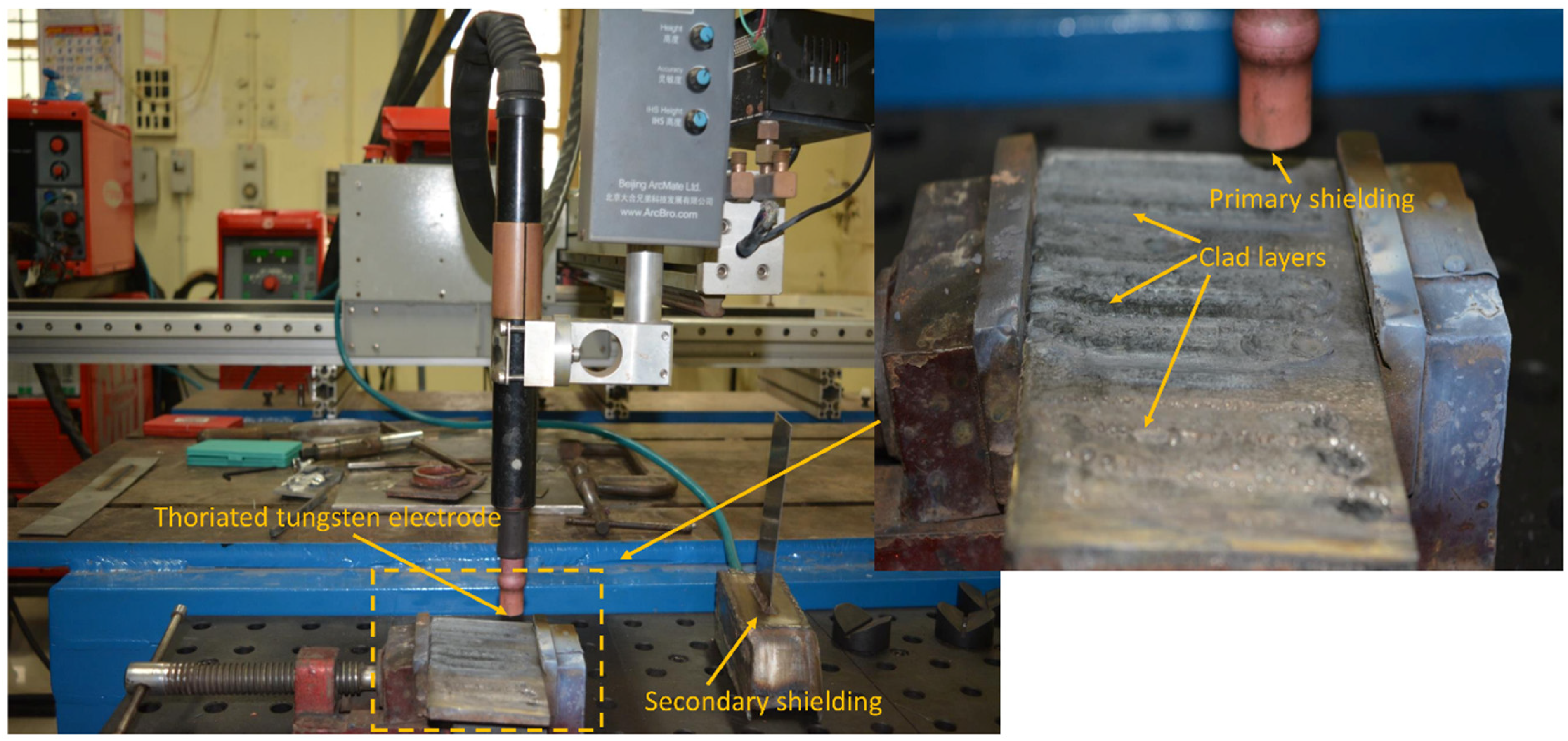
Experimental setup of the tungsten inert gas (TIG) cladding technique and deposited clad layers.
The deposited clads were sectioned and thoroughly polished with diamond paste. Before proceeding with the characterisations, the samples are cleaned with acetone. TIG-clad cross-sectional images are examined using a scanning electron microscope (SEM) with attached energy dispersive spectra (JEOL-JSM-6380LA, Japan). The porosity of the coatings was analysed using an optical microscope attached to a biovis image analyser (ARTRAY, AT 130, Japan). The TIG processing current affects the dilution of the coating with the substrate. The dilution is calculated using the equation suggested by Yaedu and D’Oliveira
45
as follows:
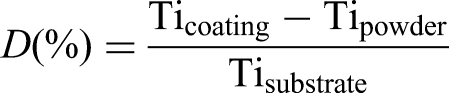
where Ticoating represents the percentage of the Ti content in the coating, Tipowder is the amount of Ti content in the powder, and Tisubstrate is the Ti content in the substrate material. The microhardness of the claddings is measured using an OMNITECH Vickers microhardness tester with a normal load of 300 g and a dwell time of 10 s. The phase analysis of the deposited clads is performed using X-ray diffraction (XRD) (DX GE-2P, JEOL, Japan). The tribological performance of clads was also investigated using a pin-on-disc tribometer (DUCOM, Bangalore, India). The clad sample was cut into 6 × 6 × 5 mm and utilised as a pin against the Al2O3 counterbody. To investigate the wear behaviour, process parameters such as temperatures (200 °C, 400 °C and 600 °C) and loads (20 N and 40 N) were used. All tests were carried out with a constant sliding velocity and distance of 1.5 m/s and 2000 m, respectively.
The tribological studies are carried out on a pin-on-disc tribometer (DUCOM, Bangalore, India) by varying process parameters such as load and chamber temperature. Furthermore, the tested samples are characterised using SEM and XRD to determine the wear mechanism and phases at elevated temperatures.
3 Results and discussion
The deposited claddings in Figure 2 are very well diluted with the substrate. The average porosity of all claddings is noted to be <1%. Clad A dilution ratios at 95, 105, and 115 A were 31.5%, 44.77%, and 61.8%, respectively. Clad B's dilution ratios at 95, 105, and 115 A were 44.4%, 46.66%, and 69.5%, respectively. The thickness of both clad A (NiCrFeSiB/WC/MoS2) and clad B (NiCrFeSiB/WC/BaF2) increased as the TIG current increased from 95 A to 115 A. The WC particles in the nickel matrix are well dispersed, and WC particle dissolution was shown to increase with increasing TIG current. This could occur due to a change in energy input, which changes the solidification rate of the clad layer. 46 At 95 A, the clad layer thickness is relatively thin (1.1–1.20 mm). Clad layer thickness was found to be in the range of 1.28–1.35 at higher TIG currents of 115 A. More pores are observed at a lower current of 95 A than at a higher current. This could be attributed to insufficient heat input, which causes Ar shielding gas entrapment in the clad. There are no visible cracks along the interface, and the clad is metallurgically bonded to the substrate under all processing conditions. Due to their higher density and melting point than nickel alloy, few WC particles are collected at the bottom of the SEM images. It is also clear that the convection current in the weld pool is insufficient to keep the WC particles from sinking to the bottom. 47
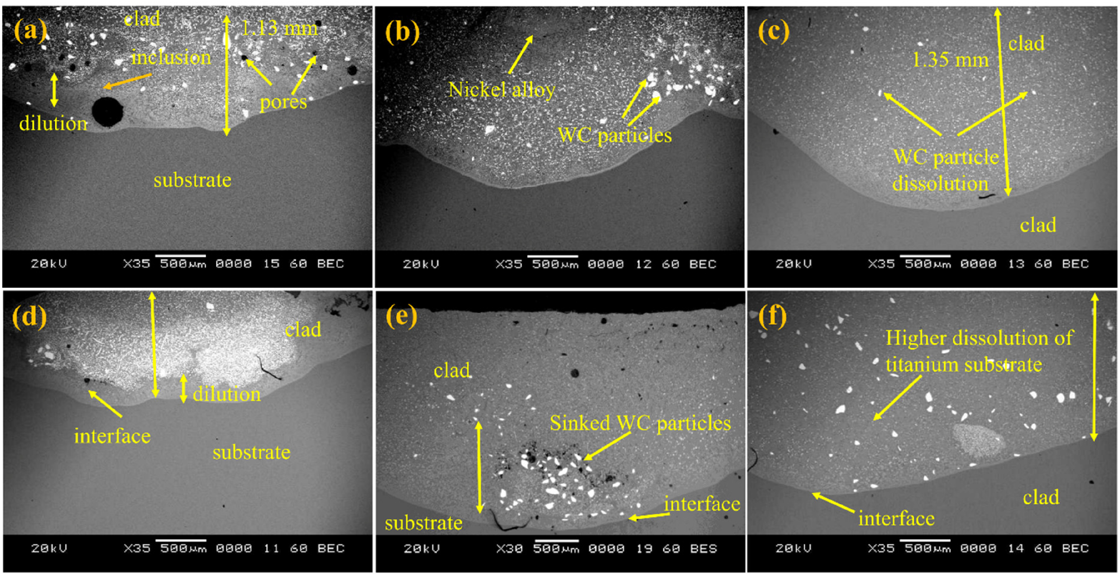
Scanning electron microscope (SEM) micrographs of the clad A at (a) 95 A, (b) 105 A, and (c) 115 A; clad B at (d) 95 A, (e) 105 A, and (f) 115 A.
This phenomenon could also be used to limit cladding diffusion with the substrate. The magnified SEM images of clads A and B deposited at different TIG currents are shown in Figure 3. Energy dispersive X-ray spectroscopy (EDS) analysis was performed on all deposited coatings due to WC particle dissolution and substrate dilution with increasing TIG current. When the TIG current was increased from 95 A to 115 A in clad A, the dilution increased from 28.63 wt% to 55.62 wt% (As shown in Table 1). Similarly, as the TIG current increased from 95 A to 115 A, the dilution of titanium substrate in the clad increased from 39.98 wt% to 62.56 wt%. All nickel alloy, WC, solid lubricants MoS2, and BaF2 were well dispersed in the claddings. However, mechanical properties would change due to the higher dilution. Interdendritic eutectic precipitations are found near the interface. The disappearance of blocky WC particles indicates that heat input has increased. However, as the TIG current increases, cracks and pores may form. It was discovered that the TIG current gradually reduced pore formation. More molten was created and filled the pores in the clad as the TIG current increased. However, some pores remain in the clad, which could be attributed to differences in particle sizes between WC and solid lubricants. The white blocky particles are primarily made up of W and C. Instead of forming separate phases such as tungsten carbide, the added solid lubricants were well dissolved in the cladding. Due to the higher dilution, more titanium percentage was present in 115 A processed clad than in the 95 A processed clad (Table 1). The EDS analysis showed that clads A and B solid lubricants were well dissolved. It can also be observed that the interface between the clad and substrate increased with the temperature change. At 95 A, the interface of both coatings was approximately 120 µm. With the temperature increase to 115 A, the clad interface was noted as 250 µm (Figure 3).
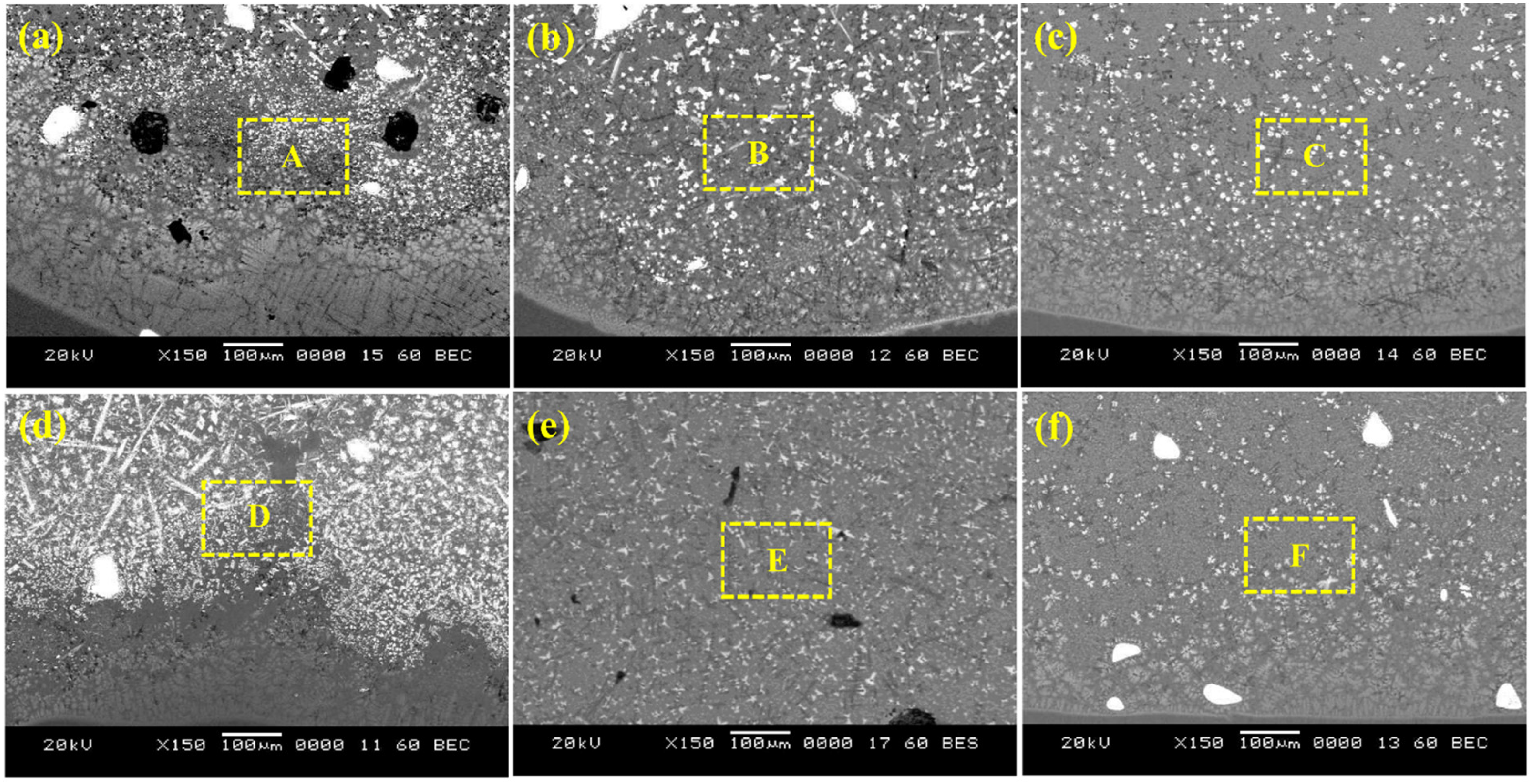
Microstructures of clad A at (a) 95 A, (b) 105 A, and (c) 115 A; clad B at (d) 95 A, (e) 105 A, and (f) 115 A.
EDS analysis corresponding to SEM images is shown in Figure 3.
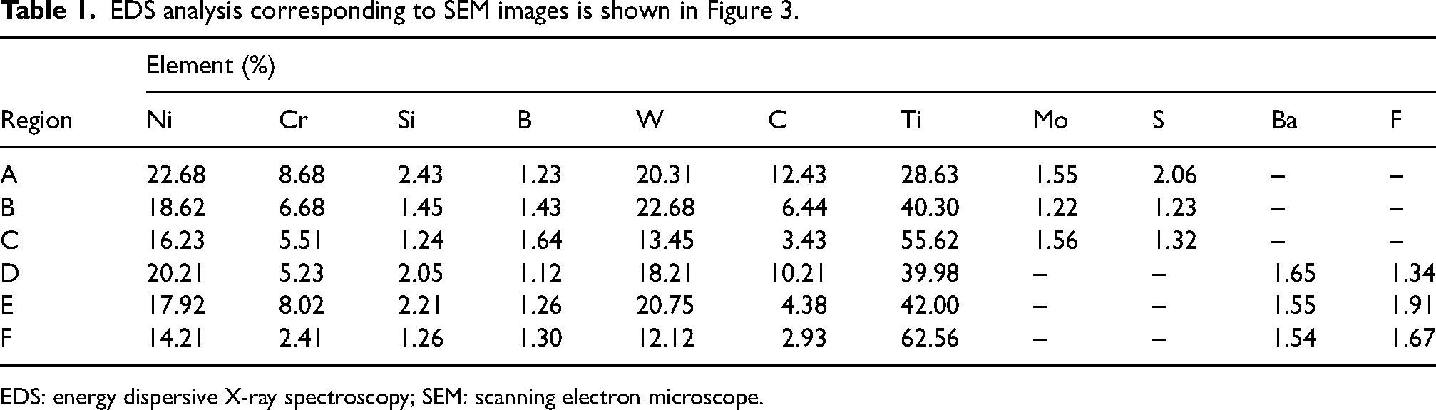
EDS: energy dispersive X-ray spectroscopy; SEM: scanning electron microscope.
The number of indentations along the cross-section was used to calculate the microhardness of the clads deposited at different currents. In this experiment, a 300 gf load was indented on the clad cross section for 10 s. The Vickers microhardness distributions of the clads are depicted in Figure 4. Because hardened reinforcing phases such as Ti x Ni y , TiW, and TiN are dispersedly distributed in the cladding layer, the composite coatings’ microhardness is greatly improved, resulting in a dispersion-strengthening effect. The crystal grains are refined during the crystallisation process, resulting in a fine-grained strengthening effect on the cladding layer. Hardening and plastic reserve capacities are more significant in the hard/soft phase composite structure. As a result, the composite coating is significantly harder than the substrate. The hardness of the clads was found to decrease with the TIG current, which could be due to a change in chemical composition. Furthermore, hardness values are not uniform along the clad depth. The results show that its hardness increases as the clad moves away from the substrate. The presence of WC particles in the matrix has an effect on the formation of hard phases within the nickel alloy matrix. The abrupt increase in microhardness value indicates the WC particle distribution in the clad. The dilution caused by the change in current affected the average microhardness values of the clads. At a lower current of 95 A, along the interface of the clad A, hardness decreased rapidly from 500 to 330 HV. However, as the TIG current was increased to 115 A, the microhardness values gradually decreased from 390 to 330 HV. The phenomenon described above is a thermal gradient phenomenon.
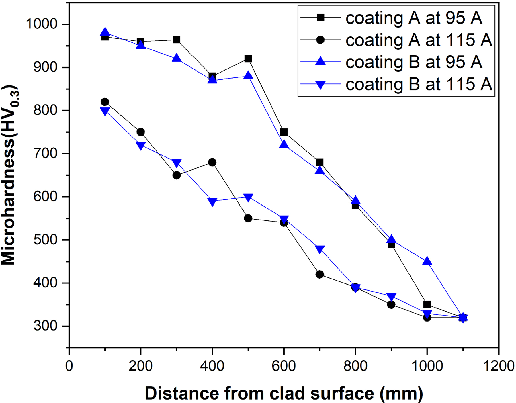
Microhardness profiles of clads A and B using different currents.
Figure 5 depicts the XRD pattern of both nickel alloy clads deposited at 95 A. The XRD patterns of clads A and B show a similar sequence of peak formation. Because of the high heat input in the clad, WC particles dissolve and form the W2C phase. The formation of the intermetallic phase Ni4W in the clad layer may be due to the interaction of the nickel alloy matrix with the free W. The TIG and microwave hybrid heating treated clad contains typical phases such as Ni4W, WC, W2C, Cr23C6, Ni3Si, Ni3B, TiNi, TiC, Mo, and BaF2. Due to dilution, intermetallic compounds such as TiNi and TiC were present in the clad. The chemical reactions that occurred among the powder particles resulted in the formation of the intermetallic compound Ni4W. The phases such as W2C and Cr23C6 showed higher hardness in the clad. Mo and BaF2 peaks have emerged as a result of the mixing of solid lubricants. These phases indicate adequate lubrication in the clad layer. The results obtained in the present analysis are similar to the previous studies by Pang et al. 48 and Çelik. 49
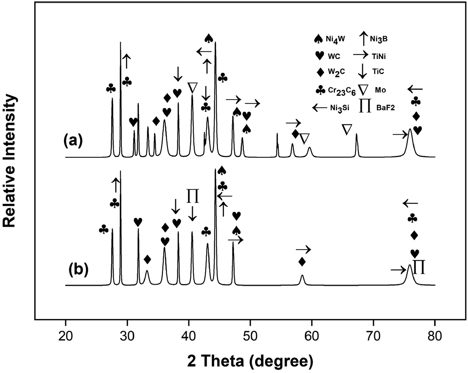
X-ray diffraction patterns of deposited clad A and clad B at tungsten inert gas (TIG) current of 95 A.
It was observed that the average coefficient of friction of clad A was reduced from 0.52 to 0.36 under 20 N load as increasing temperature from 200 °C to 600 °C. Similarly, the coefficient of friction of clad B was reduced from 0.49 to 0.32 with the increasing temperature from 200 °C to 600 °C. Figure 6 depicts the wear rates of composite coatings at various loads and temperatures. Clad B had the lowest wear rate of 6.08 × 10⁻³ mm3 (Nm)−1 among all clads tested at 20 N and 600 °C. Wear rates of clad A increased slightly with increasing temperature, regardless of load change, which could be attributed to the ineffectiveness of MoS2 solid lubricant at higher temperatures. The wear rate of clad A increased slightly more than the wear rate at 200 °C at 400 °C. The wear rate of clad A increased from 6.85 × 10⁻³ to 7.44 × 10⁻³ mm3 (Nm)−1 as the temperature increased from 200 °C to 600 °C under 20 N load. With a load of 40 N, the wear rate increased from 7.02 × 10⁻³ to 8.85 × 10⁻³ mm3 (Nm)−1 as the temperature increased from 200 °C to 600 °C. Under 20 N load, the wear rate of clad B decreased from 6.98 × 10⁻³ to 6.08 × 10⁻³ mm3 (Nm)−1 as the temperature increased from 200 °C to 600 °C. The wear rate at 40 N load decreased from 7.11 × 10⁻³ to 6.36 × 10⁻³ mm3 (Nm)−1 as the temperature increased from 200 °C to 600 °C. This could be due to the effectiveness of BaF2 solid lubricant at temperatures ranging from 500 °C to 600 °C. At lower temperatures, however, MoS2 solid lubricant prevented material loss better than BaF2 solid lubricant.
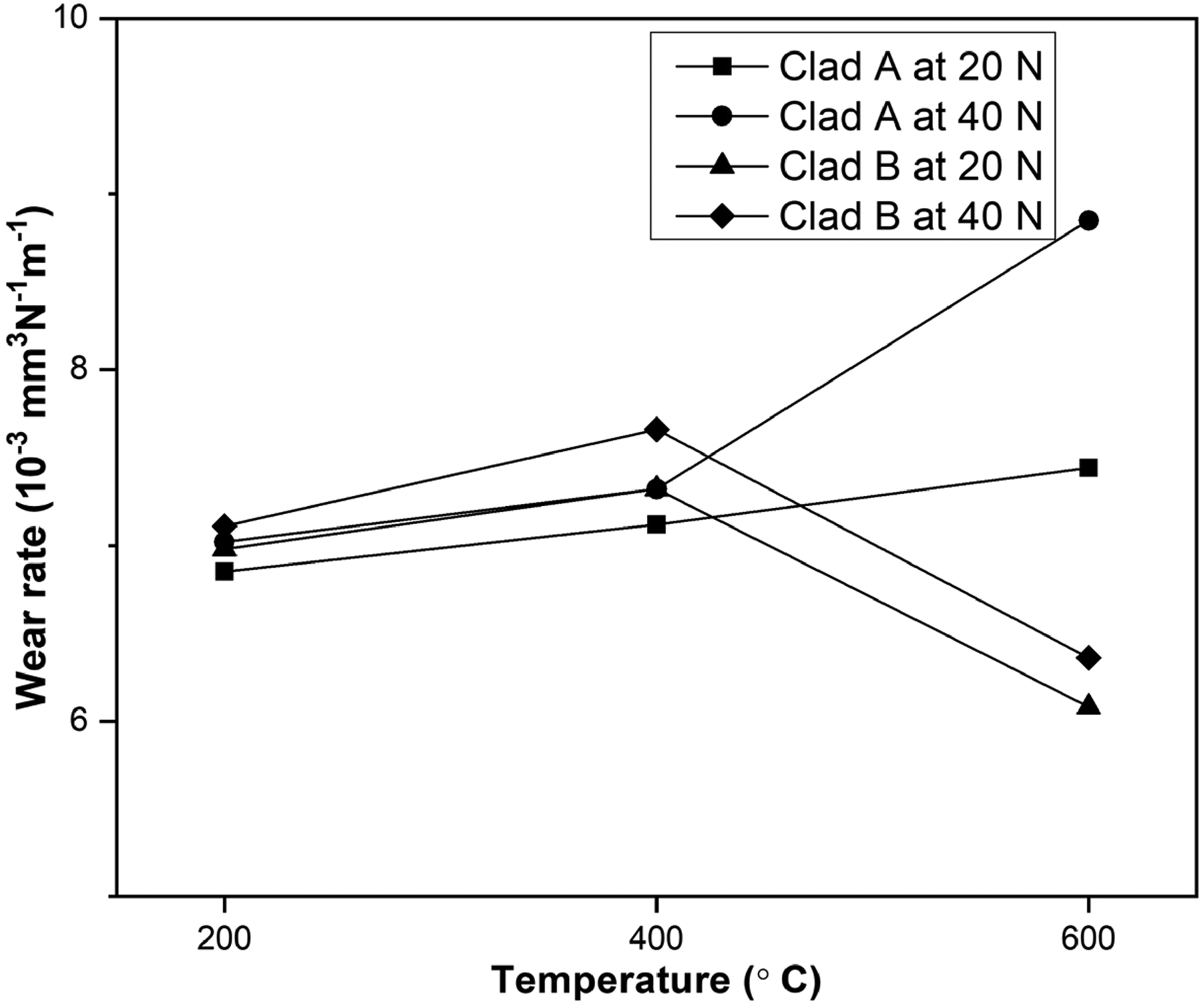
Wear rates of clads A and B against Al2O3 counterbody at different temperatures and loads.
Surface morphologies were characterised using SEM to discuss the tribological mechanisms of both clads at different temperatures and loads, as shown in Figure 7. At 600 °C, the wear track surface is mostly covered by grease-like material. As the temperature rises from 200 °C to 600 °C, the amount of this black thin layer on the wear track surface increases. Some wear debris and lubricant layer adhere to the surface of the worn samples in clad A at a lower temperature of 200 °C. It is relatively flat and smooth, with no obvious furrows or deep scratches. This finding implies that the coating produces less wear debris, which reduces the risk of ‘three-body’ wear between the friction pair's elements due to wear debris scratching up the wear surface. However, as the temperature rises, wear debris accumulates on the surface, causing more material to come into direct contact with the alumina counter body. Similarly, lubricant layer formation was observed in clad B at higher temperatures. More material removal was observed at lower temperatures owing to insufficient lubrication of BaF2 at lower temperatures. As the granular wear debris peels off the coating, there is a significant region of peeling, or pits, on the surface of the wear track. According to microscopic inspection, the worn track structure has micro-cracks or is loose. The formation of dense through-cracks between pits causes this phenomenon. The connections between these peeling-induced pits further crush the coating structure. Lower temperature clad A and clad B wear rates decreased as dilution increased. However, at higher temperatures, the dilution phenomenon slowed the material's removal. As shown in Figure 7, at 200 °C, a lower amount of oxide layer and thick lubricant layer formed on the surface of clad A (as shown in Table 2) at both 95 A and 115 A TIG current fabricated layers. At 600 °C, a greater amount of oxide layer and a thick lubricant layer formed on the clad B surface (Table 2). The higher dilution of titanium in nickel alloy clads at higher temperatures has proven beneficial, but the dilution effect is detrimental to tribological properties at lower temperatures.
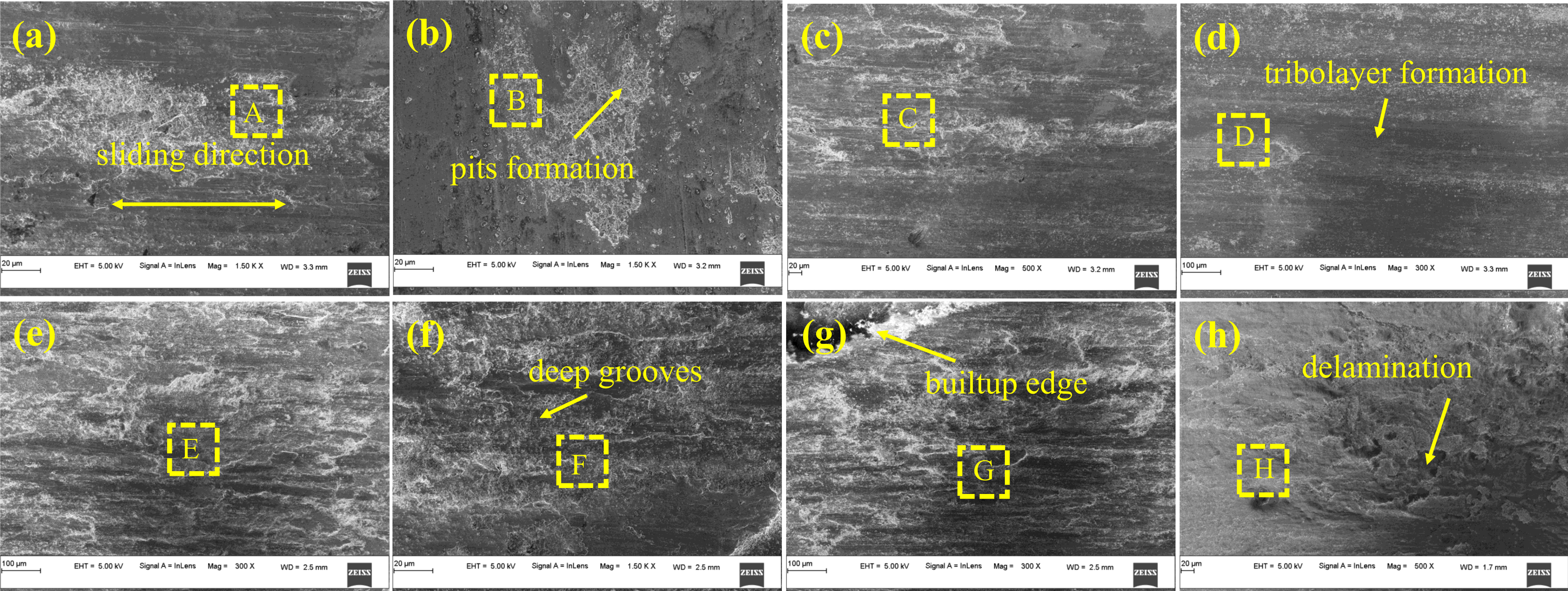
Scanning electron microscope (SEM) micrographs of worn surfaces of clad A at 95 A: (a) 200 °C and (b) 600 °C; clad A at 115 A: (c) 200 °C and (d) 600 °C; worn surfaces of clad B at 95 A: (e) 200 °C and (f) 600 °C; clad B at 115 A: (g) 200 °C and (h) 600 °C.
EDS analysis corresponding to SEM images is shown in Figure 7.
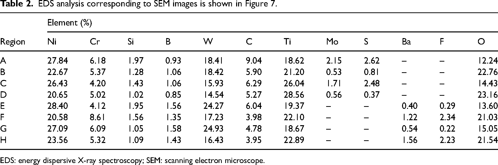
EDS: energy dispersive X-ray spectroscopy; SEM: scanning electron microscope.
4 Conclusions
Tribo-layers containing Mo in NiCrFeSiB/WC/MoS2 composite coating and BaF2 in NiCrFeSiB/WC/BaF2 coating were crucial in lubrication and wear reduction. Due to the reinforcing phases in both clads the average microhardness of coatings has been significantly improved compared to the substrate (approximately 320 HV0.3). The average microhardness of clad A at lower and higher TIG currents was noted as 771 HV0.3 and 531 HV0.3, respectively. Similarly, the average microhardness of Clad B at both higher and lower currents was noted as 717 HV0.3 and 518 HV0.3, respectively. The wear resistance of titanium alloy was greatly improved by incorporating MoS2 and BaF2. The hardness and wear behaviour of the NiCrFeSiB/WC/MoS2 coating was slightly impacted by the dilution at lower temperatures. The wear rate of NiCrFeSiB/WC/BaF2 coating at higher temperatures is shown to be prominent with the increase in dilution ratio.
Footnotes
Declaration of conflicting interests
The authors declared no potential conflicts of interest with respect to the research, authorship, and/or publication of this article.
Funding
The authors received no financial support for the research, authorship, and/or publication of this article.