
Abstract
A smart antenna, which consists of several antenna elements makes a gain at the desired direction, makes nulls at the direction of interferers. In this article, the bit error rate is measured in different directions and distances, and the method of the minimum variance is used with the concept of the link budget when the weights of the multiple input multiple output (MIMO) radar are calculated with the number of N receiver elements and with the number of M transmitter elements. The less the number of interferers is, or using MIMO, the better the system is.
Introduction
The array antenna 1 is called a phased array antenna or a beamforming array antenna that can adjust the beampattern to the desired direction using phase shifters in systems or by digitally phased shifting the data at the back end of the receiver. A phase shifter is used at the radio frequency (RF) frequencies in the analog beamforming, 2 meanwhile a phase shifting and digitization are performed at the intermediate frequency (IF) or baseband frequency in the digital beam forming (DBF),3,4 since an antenna pattern is formed by digital signal processing.
Current beamforming array antennas, where the pattern is shaped to a certain optimal standard electronically, are called smart antennas. 2 Alternative names of smart antennas are digital beamforming array antennas or adaptive array antennas when an adaptive algorithm is used.
Current smart antennas change the beampattern according to the optimum reference value, and there are methods such as maximum signal to interference ratio (SIR), maximum likelihood (ML), minimum variance, and minimum mean square error. The ML scheme is identical to the minimum variance except that the interfering signal is assumed to follow a zero-mean Gaussian distribution.
The multiple input multiple output (MIMO) radar 5 has attracted more attention due to its remarkable advantages over phased arraybased radars, such as high spatial resolution, accurate target detection, and strong interference suppression. The performance benefits of the MIMO radar come from the multiple orthogonal signals and larger virtual arrays. To improve the signal to interference noise ratio (SINR)6–8 of targets, a beamformer is designed to gather the echo beam energy of MIMO radar.
The MIMO radar is divided into a distributed MIMO (DMIMO) and a collocated MIMO (CMIMO) radar9–11 based on the antenna configuration. The DMIMO uses widely separated antennas, and the CMIMO uses the closely spaced antenna to achieve waveform diversity. However, the CMIMO radar experiences deteriorated performance due to the fading of the radar cross-section (RCS) of a target. Whereas the DMIMO radar can accomplish a large amount of spatial diversity gain using the multiple aspects of a target. We use “MIMO radar” instead of “CMIMO radar” for readability.
In this article, we applied the smart antenna to a radar using a MIMO system and compared the performance of the receiver using the bit error rate (BER). The BER varies depending on the incidence angle and the number of antenna elements.
This article is structured as follows. Section II describes the MIMO using uniform linear arrays. Section III explains calculating the weight of the beamformer. Section IV describes the weight calculation using the link budget. Section V describes the simulation conditions. Section VI describes the results and analysis. Section VII concludes the article.
MIMO radar using uniform linear arrays
A smart antenna is composed of several antenna array elements and can receive a signal from a desired direction and reduce the strength of signals in unwanted directions.
The output of the antenna element is weighted by a beamformer to make the main beam and null. To reduce interferences, the beamformer places nulls in the interfering signal and adjusts to have a constant gain in the desired signal.
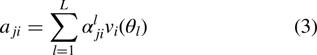
Assuming that the smart antenna is applied to the MIMO radar and the number of receivers is N, the number of transmitters is M, the number of each antenna element is K, and the number of fading is L, the reaction of the MIMO radar by direction of arrival (DoA)
12
is


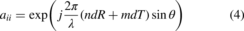
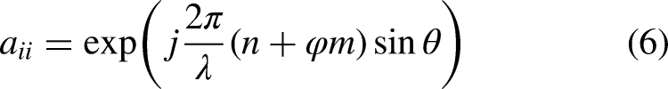
If the i-th receiver response from the j-th transmitter
12
is aji,
Weight calculation of beamformer
The received signal from the i-th receiver
12
is


The output of the beamformer at the i-th receiver
12
is

The i-th average output power
12
is


The goal of beamforming is to find a weight vector wi12–15 that minimizes the interference Ii according to wiHaii = 1, and the fixed weight of the i-th receiver using the Minimum Variance2,16 is


Weight calculation with link budget
In equation (10), PjGji can be replaced with the received power margin, that is, PM. In this case, since the distance information using the link budget is input, the antenna weight can be calculated according to the distance.
This received power consists of more realistic elements like transmitting power, transmitting antenna gain, receiving antenna gain, (component loss is ignored), and receiver sensitivity, and also includes distance information.
The power margin of the i-th receiver from the j-th transmitter, PMR,ji
17
is defined as follows:


Weight can be obtained by substituting equation (21) into equation (17) and by using the minimum variance applying the link budget.
Simulation conditions
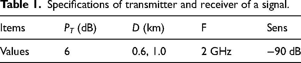
The number of interferers is 1, 6, and 16, respectively. The reason is that the number of interferers was set to small, medium, and large values. The RF output and distance of the transmitter and the receiver are shown in Table 1. We assume the RF power of the transmitter is 6 dB, and 0.6 or 1.0 km away from the receiver. The transmitting antenna gain, the receiving antenna gain, and the receiver sensitivity of the signal and the interferers are 0 dB, 0 dB, −90 dB, respectively.
Specifications of transmitter and receiver of a signal.
The RF output, DoA, and distance of each interferer are shown in Table 2. When the number of interferers is 1, assigned to INFR0, when the number of interferers is 6, assigned to INFR0 ∼ INFR5, and when the number of interferers is 16, assigned to INFR0 ∼ INFR15.
Initial conditions of each interferer.
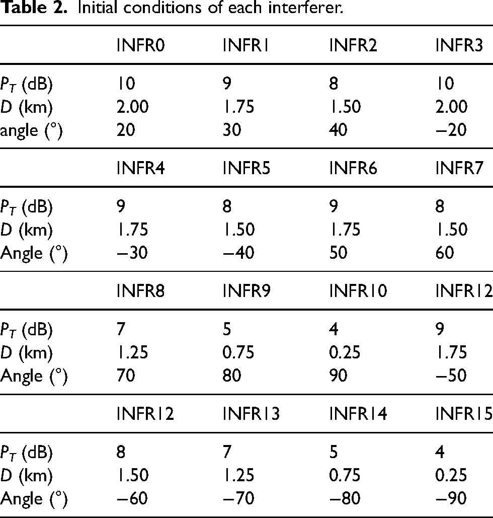
Each RF power of the interferers is 4∼10 dB, their DoAs are distributed from −90° to 90°, and 0.25 ∼ 2 km away from the receiver.
Results and analysis
Figure 1 shows that the desired signal has an incidence angle of 5° or −10° and the number of interferers is 1 and from 20°.

Radar beampatterns with 1 interferer at an incidence angle of 5° (upper) or 10° (lower) at D = 0.6 km.
Figure 2 shows that the desired signal has an incidence angle of 5° or −10°, and 6 interferers (20°, 30°, 40°, −20°, −30°, −40°) exist.

Radar beampatterns with 6 interferers at an incidence angle of 5° (upper) or −10° (lower) at D = 0.6 km.
Figure 3 shows that the desired signal has an incidence angle of 5° or −10°, and 16 interferers (20°, 30°, 40°, −20°, −30°, −40°, 50°, 60°, 70°, 80°, 90°, −50°, −60°, −70°, −80°, −90°) exist.

Radar beampatterns with 16 interferers at an incidence angle of 5° (upper) or −10° (lower) at D = 0.6 km.
In Figures 1–3, it can be seen that the receiver using MIMO at the same distance of 0.6 km indicates the exact DoA and shows much better performance even with a large number of interferers than the receiver without MIMO.
Figure 4 shows the BERs of the receiver without MIMO, the BERs with a large number of elements (N = 8) show better performance than the BERs with a small number of elements (N = 5).

BERs of receiver without MIMO at D = 1.0 km, N = 5 and 8, θ = 5°.
Figures 5–7 show the BERs of receivers with and without MIMO are plotted for the case where the number of the receivers is 5 (N = 5), the number of the transmitters is 3 (M = 3), the incidence angle is −5 or 5°, the distance is 0.6 or 1.0 km, and the number of interferers is 1, 6, and 16, respectively.
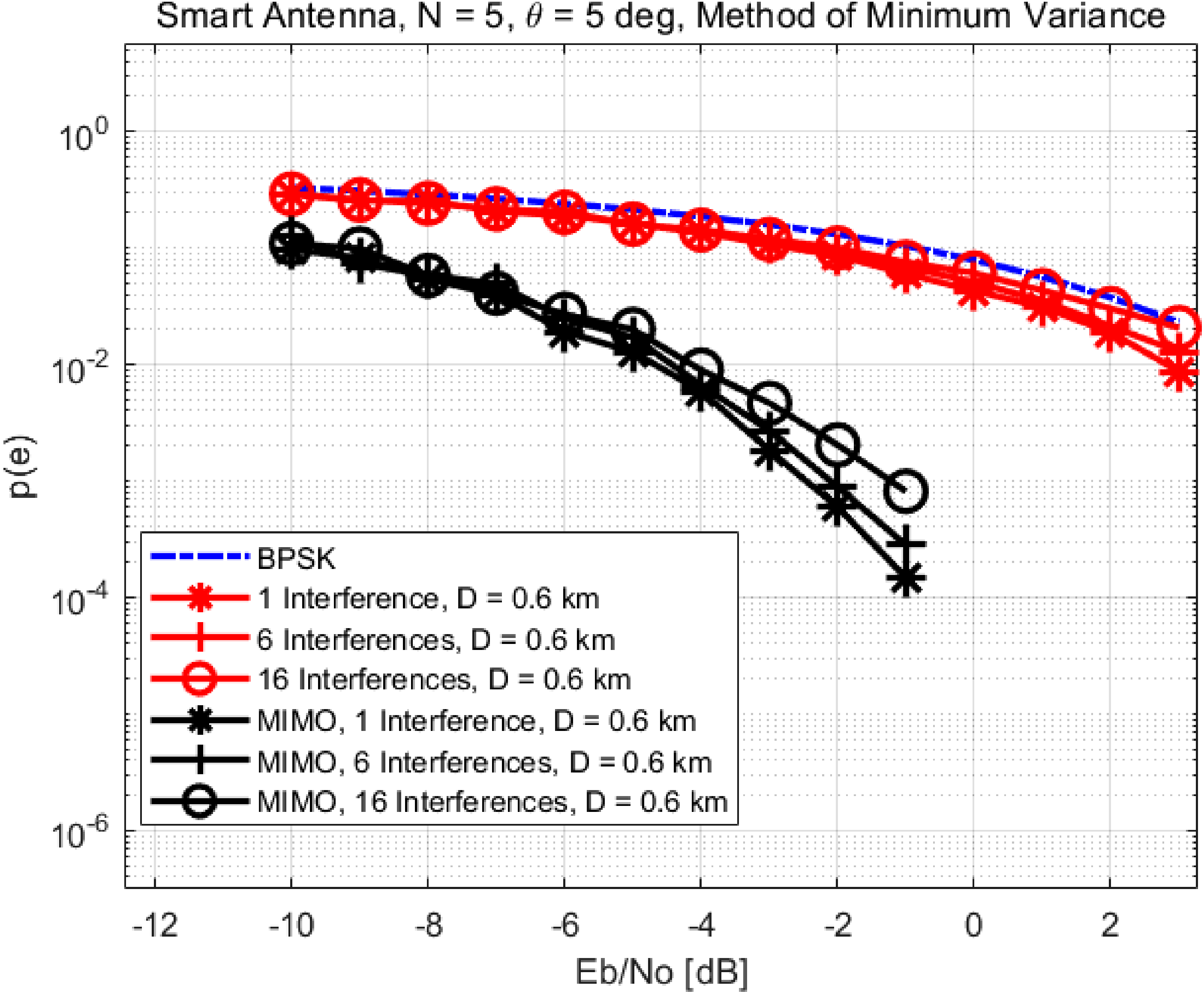
BERs of receivers at D = 0.6 km, N = 5, θ = 5°.

BERs of receivers at D = 0.6 km, N = 5, θ = −5°.

BERs of receivers at D = 1.0 km, N = 5, θ = 5°
In Figures 5 (DoA = 5°) and 6 (DoA = −5°), it can be seen that the receiver using MIMO at the same distance of 0.6 km shows similar results regardless of DoA and has better BER than the receiver without MIMO. Additionally, BERs also worsen as the number of interferers increases.
In Figures 6 (D = 0.6 km) and 7 (D = 1.0 km), it can be seen that the BERs of the receivers with or without MIMO also worsen as the distance increases.
Figures 5–7 showing the BERs can confirm the superiority of the receiver using MIMO.
Conclusion
The MIMO radar calculates the weights of several antenna elements, receives the signal from the desired direction, reduces the signals from unwanted directions such as noise, arranges nulls in the direction of the interfering signals, and adjusts the number of elements of the transmitters and the receivers. In this article, we compared the beamformer using MIMO with the non-beamforming system.
It can be seen that the BER is worse as the number of interfering signals increases, but the BER is better than when there is a MIMO system in the same condition.
Footnotes
Acknowledgements
This research was partially supported by the ‘CAS500 P2 program' of the NRF (2022M1A3A4A06095848) and ‘C-band SAR Payload Development program’ of the KARI funded by the Korean government (MOE).
Declaration of conflicting interests
The author(s) declared no potential conflicts of interest with respect to the research, authorship, and/or publication of this article.