
Abstract
A method based on sparse array is applied to direction-of-arrival estimation of passive radar in this paper to increase the number of resolvable sources and improve the direction-of-arrival estimation performance for coprime array. The virtual symmetric non-uniform linear array of coprime array based on passive radar signal model is introduced. Considering the impact of direct wave, extensive cancellation algorithm is used to cancel the direct wave, with the conventional MUSIC with spatial smoothing algorithm and virtual aperture filling applied on the sparse array of passive radar; the resolution of target is low in the low signal-noise-ratio. To effectively improve the estimation of the target under the low signal-noise-ratio, a noise subspace reconstruction method is proposed. The proposed direction-of-arrival estimation method can improve the direction-of-arrival estimation performance of passive radar. The simulations are provided to demonstrate the effectiveness of the proposed method.
Introduction
Passive radar has the advantages of high concealment and good maneuverability compared with active radar, and it has received wide attention in recent years.1,2 It is widely used in range Doppler estimation inverse synthetic aperture radar imaging and azimuth estimation of airborne moving targets.3,4 The uniform linear array (ULA) is widely used because of its simple structure. However, due to the poor resolution of radar range Doppler, there are usually multiple targets within a range Doppler unit. When the number of airborne targets is larger than the number of array sensors, the arrival angle of the target cannot be estimated. This paper aims at solving the problem of direction-of-arrival (DOA) estimation when the number of targets is larger than the number of physical sensors of the array.
DOA estimation is a typical issue in passive radar. The traditional ULA is limited in its freedom due to the limitation of its aperture and sensor spacing. Sparse array (SA) opens a new approach to DOA estimation, which has high degrees of freedom (DOFs) offered in the different SA domain.5,6 Coprime array is an example of SA which is obtained from two ULAs with different sensor spacing. It is based on MIMO radar and uses the relationship of phase differences between sensors to reconstruct the covariance matrix, thereby greatly improving the DOFs, angle resolution, and estimation accuracy.7,8 Due to the large distance between the sensor, the coprime array reduces the influence of mutual coupling between sensors and improves the performance of DOA estimation. 9 In addition, the coprime array has larger DOFs and can significantly increase the number of estimation targets. So, the coprime array has become a research hotspot in the field of array information in recent years.10–12
Using coprime array can increase the DOFs without any increase of physical sensors. Coprime array for SS-MUSIC algorithm and the modification of spatial smoothing step were introduced in Pal and Vaidyanathan, 13 but only continuous virtual arrays are used. However, there are discontinuous sensors in the virtual array, which will lose part of the virtual sensor and reduce the DOA estimation performance of the array. Liu et al. 8 proposed a method of filling non-continuous virtual sensor, which can fill the missing array sensor positions, thereby improving the freedom of the array. Vacancy array was also studied in Chengwei et al. 14 and Zhang et al. 15 By supplementing the missing sensors, the number of consecutive sensors is increased, and the information of the virtual sensors is fully utilized, thereby improving the performance of DOA estimation. Although this SA has been separately reported in the paper, they are all verified in active radar.
In this paper, the coprime array is used on passive radar to improve the resolution and estimation accuracy. The remainder of this paper is organized as follows. In the next section, the received signal model of passive radar and coprime array will be established. Then, the DOA estimation algorithm based on coprime array is proposed in the “Proposed DOA estimation method in passive radar” section. Some simulations are conducted to verify the performance and the resolution of the proposed method in the “Simulation results” section. Finally, we conclude the paper in the “Conclusions” section.
Signal model
Passive radar model
A passive radar is a fascinating device that does not transmit any electromagnetic energy when sensing. It obtains the target signal by performing cancellation processing on the data received by the early warning channel and the reference channel. The reference signal can be obtained as follows

The signal received by the gth (g = 1,2…G, G is the number of array) early warning antenna can be expressed as

Coprime array
Coprime array was proposed by Vaidyanathan and Pal in 2011.16,17 It is a non-ULA, which is composed of alternating sparse ULA with different spacing between two sensors. Figure 1 shows the basic structure of a typical mutual mass array. Among them, one subarray has 2M-1 array sensors, the sensor spacing is
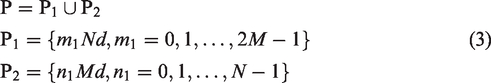
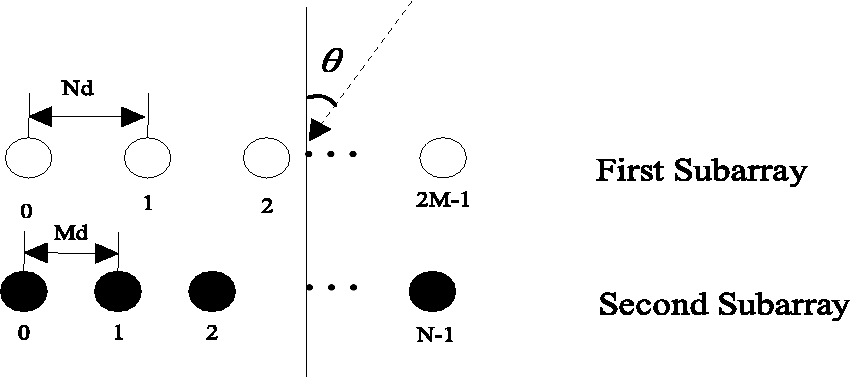
The structure of coprime array.
Assume that there are K far-field echo signals impinging on the arrays, and use
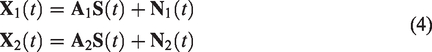

Then, the received signal is


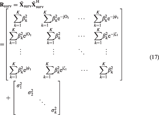
The covariance matrix of the received signal can be expressed as

Proposed DOA estimation method in passive radar
In this section, the proposed DOA estimation method in passive radar system will be presented. The received signal is preprocessed in the “Cancellation the clutter and direct wave” section, and the “Proposed DOA estimation method” section introduces the proposed method and analyzes the Cramer–Rao bounds (CRB).
Cancellation of the clutter and direct wave
In passive radar, the signal received by the early warning antenna includes not only the target echo, but also multipath clutter and direct wave direct signal. Especially, the direct wave reaches the early warning antenna without any reflection and it leads to the strength of the direct wave being greater than the target echo signal. So, the direct wave signal will mask the target echo signal if DOA estimation is performed directly without processing, and the result of the DOA estimation will be the incident direction of the direct wave. Therefore, we need to eliminate direct signals and clutter signals and obtain target echo signals to achieve the target DOA estimation.
Colone et al.
18
introduced an extensive cancellation algorithm (ECA) to filter out direct wave and multipath clutter, so as to obtain the true target echo signal. Passive radar signal reception consists of a reference channel and a monitoring channel. According to Colone et al.,
18
the relationship between the monitoring channel and the reference channel received signal is written as


Using the least square method, the suppressed signal can be obtained as

We can obtain the echo signal after the cancellation

Proposed DOA estimation method
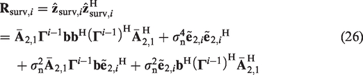
Through ECA processing, the direct wave and multipath clutter are eliminated to obtain the target echo
In matrix
It only used the one same sample information in the same phase in Pal and Vaidyanathan
13
and Zhang et al.,
15
this method will cause loss of utilization data. The more the sample redundancy is, the bigger the error difference will be. Therefore, in order to improve the estimation accuracy, the method in this paper makes full use of all sample information and uses the average wave path difference to equivalent
By vectoring, a new vector is obtained as


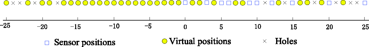
The VSNLA of co-array with M = 3, N = 5.
According to equation (18), the flow pattern of virtual array contains missing sensors. It will lose DOF if we use continuous virtual array sensors for estimation. Construct the array as follows

Assuming that

We can approximate
Then, we can complement a discontinuous virtual array into a continuous virtual array

The forward and backward spatial smoothing are carried out for reconstructed continuous virtual array


Taking the average of

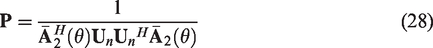
The spatial spectrum of the incoming target direction is expressed as
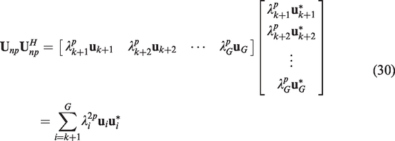
However, when the signal-noise-ratio (SNR) is low, the difference between the eigenvalue corresponding to the signal and the eigenvalue corresponding to the noise is relatively small, and the SS-MUSIC algorithm is difficult to estimate the target. Therefore, we weighted the noise subspace corresponding to

Then
The eigenvectors corresponding to noise are weighted by noise eigenvalues, and the different effects of the eigenvectors corresponding to different noise power on MUSIC spectrum are strengthened. The new noise subspace is obtained by selecting the appropriate weighting coefficient, which is substituted into equation (28), and the DOA of the source can be estimated through spectral peak search.
Based on the above discussion, the proposed method in the passive radar can be expressed as follows:
Step 1: By canceling the clutter and direct wave in the “Cancellation of the clutter and direct wave” section, the target echo is obtained. Step 2: We can get the covariance matrix of the sensor array by calculating. Step 3: The virtual sensor is constructed and the missing array is supplements. After that, spatial smoothing is carried out. Step 4: Reconstruct the noise subspace, find the target location through spectral search.
In order to compare the advantages of this SA with ULA, we compare the CRB of different array and the proposed method.
We can obtain the CRB of ULA in Stoica and Nehorai.
19
It can be expressed as


D is the difference co-array and
By equations (31) and (32),we know that DOF have a great impact on CRB. As can be seen, SA achieves greater DOF by constructing virtual array. This will cause
Equation (34) enables us to study various parameters that affect the CRB, such as the number of snapshots and the SNR. In Liu and Vaidyanathan, 20 it is indicated that for large SNR, CRB will be improved. In the proposed method, we weighted the eigenvalues of the noise subspace to increase the gap between the corresponding eigenvalues of the signal and the corresponding eigenvalues of the noise, which is equivalent to improving the SNR. Therefore, CRB is improved and the performance of the proposed method is improved.
Simulation results
In this section, the proposed method is used to estimate the DOA of the target. The performance of the proposed method and the comparison method under different source number, and the resolution and estimation accuracy of DOA estimation are simulated, respectively.
Simulation is performed for SA with M = 3, N = 5, (2M + N−1) =10. The number of snapshots is 512, and noise is additive white noise.
Detect performance
In this section, we test the detection ability of the proposed method. We consider SNR = 10, the arrivals angle of direct wave is
Figure 3(a) shows the normalized spectrum after applying the different DOA methods, but not using the ECA algorithm. We can see that when the ECA algorithm is not used, since the signal energy of the direct wave is stronger than the target echo signal, the actual target arrival angle is masked. Figure 3(b) shows the normalized spectrum after using the ECA algorithm. Comparing the two figures, it can be seen that the ECA algorithm has an effective effect on suppressing the direct wave interference to the target DOA estimation. As can be seen, both of them can resolve the eight sources sufficiently well. Next, we study the resolution of both the methods through the Monte Carlo simulations.

DOA estimation results. Here M = 3, N = 5, SNR = 10 dB. (a) Before using ECA and (b) after using ECA. DOA: direction-of-arrival.
The resolution of the different methods
To verify the estimated resolution of the proposed method in the low SNR, the different methods versus the DOA with SNR = 0 dB or =5 dB are shown in Figure 5. Figure 5 shows the presence of two signals: (a) incident angles of −3°, 0° and (b) −2°, 0°. It can be obtained from Figure 4(a) that the proposed methods can distinguish two targets at −3°and 0° clearly in the presence of Gaussian noise with SNR = 0 dB. On the contrary, they cannot be identified by the SS-MUSIC or methods in Liu and Vaidyanathan. 12 Besides, it is obvious from Figure 4(b) that the proposed methods can recognize two targets angle effectively in the case of SNR = 5 dB, while the other methods cannot differentiate two targets located at 0° and −2° successfully. Based on the discussion mentioned above, it can be deduced from Figure 4 that the proposed method has better performance of DOA estimation and identification in the case of the Gaussian noise and at low SNR, as compared to the other traditional methods.

Normalized spectrum estimation of DOA. Here M = 3, N = 5. (a) Signal located at −3°, 0° when SNR = 0 dB and (b) signal located at −2°, 0° when SNR = 5 dB. DOA: direction-of-arrival.
RMSE
The RMSE calculation formula for the estimated angle is

RMSE (in degrees) versus the SNR. Here snapshots = 512. Signal located at −3°, 5°. SNR: signal-noise-ratio.
To verify the effect of the number of snapshots on the performance of DOA methods, RMSE with SNR= 0 dB against snapshot number is depicted in Figure 6. It can be seen from Figure 6 that the RMSE acquired by these algorithms decreases gradually as the number of snapshots increases. Furthermore, it is noticeable that the RMSE obtained by the proposed method is lower than the other algorithms in the small snapshots, which implies that the developed method has a better DOA estimation performance. The results in Figures 5 and 6 verify the analysis results of CRB in the “Proposed DOA estimation method” section.

RMSE (in degrees) versus the number of snapshots. Here SNR = 0 dB. Signal located at −3°, 5°.
Conclusions
Using SA in DOA estimation algorithms in passive radar system has been shown. Aiming at issue of the poor accuracy acquired by the traditional DOA algorithms in the SA passive radar under the conditions of the low SNR, a new algorithm has been developed based on the noise subspace reconstruction theory. The ECA was introduced first to which not only eliminated the direct signal, but also eliminated the multipath clutter signal. In order to to further improve the accuracy and resolution of DOA estimation, this paper also weights the eigenvalues after subspace decomposition to improve the feature ratio of noise to target. The simulation results show that the method proposed in this paper has better performance in the case of lower signal-to-noise ratio than other methods.
Footnotes
Declaration of conflicting interests
The author(s) declared no potential conflicts of interest with respect to the research, authorship, and/or publication of this article.
Funding
The author(s) received no financial support for the research, authorship, and/or publication of this article.