
Abstract
The transport of nutrients in urban soil substrates, such as green roofs, is largely dictated by the need of the plants themselves, via adsorption by their root networks. This process pulls nutrients such as fertilizer from the soil substrate where biochar can act as a reservoir, holding the fertilizer for longer periods. Biochar is sometimes added to soils to store excess fertilizer resulting in reduced loss of fertilizer and leaching of contaminants into the groundwater. The biochar then desorbs the fertilizer (solute) into the surrounding soil. Due to limited experimental insights on the adsorption-desorption system of biochar and plants roots; we outline a complete methodology by which root structures are generated and incorporated into a fully 3D geometry. The lattice Boltzmann method is used for pore-scale simulations to compare the tap and fibrous (grass) roots’ behavior. The results show a difference in the mean contaminant breakthrough as well as in homogeneity, with the tap root having a lower mean but higher variation of concentration at the outlet. This is due to its lower surface area, which is directly linked to its adsorption capacity and the consequent quantity of biochar needed in the substrate. The lower biochar presence is quantified by a large
Introduction
Urban flooding is an important consideration given the limited catchment within most urban environments and its visible impact during extreme rainfall events. These events have become more frequent and intense in northern latitudes (Dore, 2005; Zolina et al., 2010). Green roofs (vegetated roofing) are an attractive option for sustainable urban development and are used to reduce urban flooding, improve protection and thermal performance of structures, and aid in removing contaminants (Johansson et al., 2024; Twohig et al., 2022). Although relatively “thin” in comparison to naturally occurring vegetated areas, they can be designed to maximize efficiency in water detention via understanding the dominant physiochemical mechanisms involved. Fertilizers are typically added to the soil substrate to nourish the vegetation. However, as green roofs generally lack dedicated reservoirs, excessive fertilizer application can lead to leaching and contamination of runoff with undesirable chemicals, creating an environmental burden. As a mitigation measure, biochar can be incorporated into the soil substrate to retain excess fertilizers. However, its application is typically limited (a few percent by volume) due to high cost and observed competition for adsorption sites with plant roots.
Biochar is essentially any organic matter that has been carbonized via high-temperature pyrolysis. It can adsorb both organic and inorganic contaminants such as heavy metals, fertilizers, pharmaceuticals, and dyes, among other substances (Abbas et al., 2018; Qiu et al., 2022). It does this through chemical interactions, electrostatic interaction and ion exchange, and sorption processes such as partitioning, surface sorption, pore filling, and complexation. This broad range of processes makes its application attractive in many situations requiring the remediation of a variety of contaminants. Biochar can also play a role in obstructing pesticide uptake in plants from contaminated soils, serving as an alternative method to phytoremediation by fixing the pesticide residue on the biochar itself and protecting the plants (Yu et al., 2009).
The amendment of biochar to soil substrates can make nutrients more available to the plants, but its quantity must be optimized, which is a delicate task, as different plants have varying adsorption capacities (Hou et al., 2022). Experimental and numerical studies on storm water management through green roofs also explore the role biochar has on water retention, although without the inclusion of vegetation (Gan et al., 2021, 2025). A review performed in Australia summarized globally diverse studies of reported contamination levels using indicators such as total phosphorus (Alim et al., 2022), which demonstrates the importance of understanding the relationship between water retention in green roofs with biochar and the addition of vegetation. Most experimental studies, in the field or in laboratory experiments, are often limited to a macroscopic scale in regard to the plant uptake itself, removing any insight into the microscopic (or pore) scale mechanisms which determine the process evolution. In city-scale numerical studies, the water retention capacity of green roofs is often simplified, without accounting for the saturation level of the soil substrate (Wei et al., 2023). Pore-scale numerical simulations allow for a more detailed analysis of how the local heterogeneities of the flow, reactivity, and concentration field determine the overall system dynamics; allowing finding the correlations between micro-scale phenomena with macro-scale performance and generalizing the findings.
The general numerical model used to capture adsorption-desorption within porous media is the advection-diffusion-reaction (ADR) equation. As the name suggests, a scalar quantity such as a contaminant (or solute) is transported via advection and diffusion as well as accumulated via a source or sink term coupled to a reaction rate. This equation can be treated as a continuum (Li et al., 2023; Oliveira et al., 2020; Shafabakhsh et al., 2024), a single-field model (Girault et al., 2024), or using the discrete lattice Boltzmann method (LBM), which solves the Boltzmann equation of particle motion (Zhang et al., 2024), linking microscopic particle motion with macroscopic fluid behavior. A comprehensive review of the current state-of-the-art on applied techniques can be found in Baqer and Chen (2022). At the macroscopic level, the porous medium is defined by the scalar parameters porosity
As mentioned above, pore-scale modeling aims to resolve the assumptions employed in a macroscopic description of the system by solving it directly at the pore scale. This approach brings its own challenges; such as if one chooses to utilize a continuum approach, the complex geometry alone poses a significant challenge when defining appropriate mesh resolution. One common approach is pore network models (PNMs) which define the porous medium as a series of tubes connected to reservoirs, defined using a variety of parameters, and which combined aim to mimic the material permeability (Joekar-Niasar and Hassanizadeh, 2012; Zhao et al., 2024). Alternatively, the LBM has been utilized extensively in solving flows in porous media as well as the ADR equation. Ju et al. utilized the color gradient LBM to study the impact of pore morphology on immiscible fluid infiltration of an inhomogeneous porous domain (Ju et al., 2022). Su Yan has proposed a modification to LBM by applying nonlinear drag models relating to the mesoscale porosities and velocities to more accurately capture the porous structure evolution (Su, 2024). Yu et al. introduced a hybrid immersed-boundary LBM which utilizes a finite difference scheme for calculation of reactivity within the solid matrix itself (Yu et al., 2019). Even though there are many studies utilizing or expanding LBM for handling ADR there are very limited numerical investigations on the adsorption dynamics of plants. One such promising approach was taken by Koch et al. (2018), wherein adsorption across the plant membrane as well as internal transport within the plant itself is calculated, though the model remains biologically simplistic.
Significant experimental and numerical work has been done on the transport and uptake of nutrients by root systems of plants. It is worth noting that nutrients are typically added as granules to soil substrates, and plant roots can only absorb them once they have dissolved in water. Many approaches have been taken to model fertilizer release into infiltrating water, such as the various mathematical models for controlled-release fertilizers CRFs (Irfan et al., 2018). These models utilize a variety of mass conservation equations for normal and extended release fertilizers. Empirical models for a variety of nutrients are also used, as the individual behavior of each unique compound can vary significantly from a chemical reaction perspective. Once the fertilizer is released, many transport models have also been applied. Continuum models are usually coupled to plant uptake models, taking the form of intermittent or constant flux boundary conditions (Rein et al., 2011). The fertilizer source in these uptake simulations consists of bulk sources within the soil itself, which is appropriate for larger scale models aimed at determining the effect on entire catchment systems. However, these models do not explore any localized effect of fertilizer placement within the soil and the interplay between the root structures and this heterogeneous solute distribution (Elasbah et al., 2019). Genetic algorithms have also been applied to model bulk plant uptake and have been extended to take into account vegetative competition as well (Cropper and Comerford, 2005). The transport models may also be coupled to plant growth models, such as in Rein et al. (2011), which included growth, transpiration, translocation of the nutrients within the plant itself, and a variety of biological processes such as aging, defoliation, and leaching. A strong overview of the processes which require consideration and the simplifications in use can be found in Rengel (1993). From the purely plant root morphological side, several studies such as Barber and Silberbush (1984) and Cruz et al. (2004) showed that root morphology does have an impact on plant nutrient uptake, and that plants will grow their root systems in such a way as to maximize nutrient uptake, particularly when nutrients are scarce (heterogeneous nutrient allocation in the soil). To the knowledge of the authors, there are no models that look at the micro-scale desorption and adsorption process using a biochar release mechanism and “realistic” root system, respectively, and how proximity and root morphology affect plant nutrient uptake, which is relevant to reducing breakthrough from urban green roofing systems.
To address these complex processes, this work gives a framework by which pore-scale simulations can be undertaken to analyze mass transport within an urban soil substrate such as a green roof. In the cases included here we look at the interaction between randomly dispersed particle desorbers resembling biochar and an adsorbing root-like structure under extreme rainfall conditions (Pe
Materials and methods
Lattice Boltzmann method
In this work we solve the advection-diffusion-reaction (ADR) equation

where
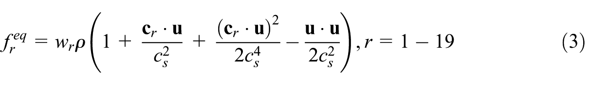
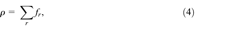
LBM is an ideal choice for solving our root-biochar transport problem due to the complex geometry involved and it allows for full field solutions of the dependent variables to be extracted at the pore scale. The system is solved on a regular lattice structure wherein each element consists of a centroid and nodes placed on a cubic convex shell. The fictive particles travel along the lattice nodes governed by probabilities appropriate for the chosen lattice geometry such that the macroscopic properties of the fluid are preserved (Succi, 2001). A 3D regular cubic lattice with 19 degrees of freedom (D3Q19) is used and the solved equation is of the form

where
where
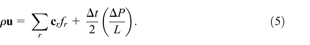
The body force
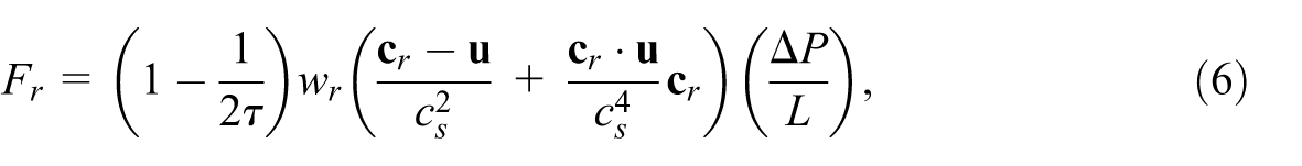
where

which can be converted easily to (mm/h), resulting in 180 mm/h, meaning the rainfall event is considered extreme or that channeling of runoff is taking place, a very possible scenario. For reference, the global record for rainfall intensity is currently 305 mm/h (WMO, 2025). The resultant mean flow velocity is averaged over the porous domain, given by
Adsorption-desorption implementation
A desorption rate is assigned to a fraction of randomly chosen particles such that their surfaces
where Da is the Damköhler number,

where
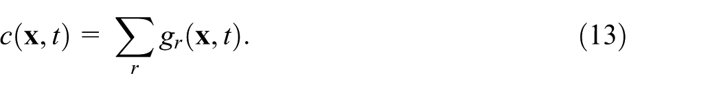
The concentration field

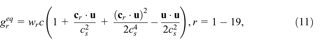
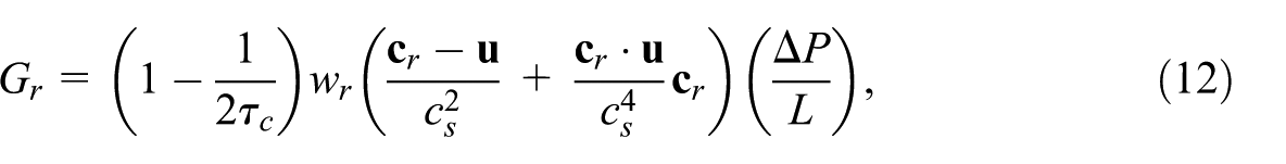
where the diffusion is related to the scalar collision time
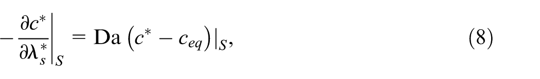
We impose a Neumann boundary condition at the adsorbing surfaces for the scalar
where
As mentioned above, we fix the Damköhler number,
Root generation algorithm
Figure 1 displays the characteristics and geometries of the generated root systems used in the is work. In Figure 1(a) the averaged cross-sectional orientations are plotted, divided into
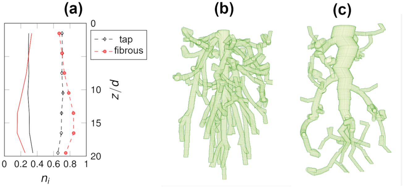
(a) Cross-sectional averaged surface node orientations divided by total cross-sectional surface area, as a function of depth by particle diameters. Red, black lines denote fibrous, tap roots, respectively. Solid: longitudinal orientation, dash: transverse. (b) Fibrous root. (c) Tap root.
The root generation utilizes the space colonization algorithm (SCA) as per Runions et al. in 2007 (Runions et al., 2007) following their 2005 publication, which introduced a biologically-motivated algorithm for generating leaf patterns in 2D (Runions et al., 2005). The later paper includes an extended algorithm for 3D and treats competition for space as the main factor for the branching structure of trees. We briefly explain how the algorithm functions for the reader’s benefit.
A singular tree node was placed at the center of the upper porous boundary. It is from the tree node that the initial branches start growing. A number of attraction points
One can alter this direction of growth by putting directional bias on it, referred to as tropisms. We have implemented gravitropism
This process continues iteratively until at least one tree node is closer to an attraction point than a user-defined kill distance
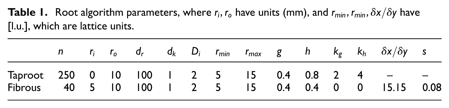
In the taproot case the primary root is created separately by assuming a linear change in primary root thickness with depth, and then some random perturbations are added laterally. The “strength” of the lateral perturbations are set by
Root algorithm parameters, where
Packed bed generation and merging
A randomly packed bed was generated using Blender. An array of monodisperse spheres with a particle diameter of
The packed bed and root domains were merged using a different algorithm, in which the user first defines a rectangular subdomain within the cylindrical sphere packing, removing any wall effects on the packed bed. The subdomain sizes are chosen large enough to host root lateral spreading and allow for the investigation of contaminant transport beyond the root vertical elongation. The root geometry was then set to replace any spheres that conflict with the root geometry. An additional buffer zone with porosity 1 is added to the upstream end of the domain. Table 2 gives the domain geometry detailsdetails and the domain is shown in Figure 2.
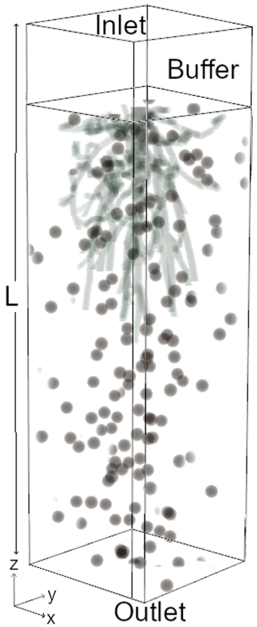
Domain schematic, where
Domain parameters. Re
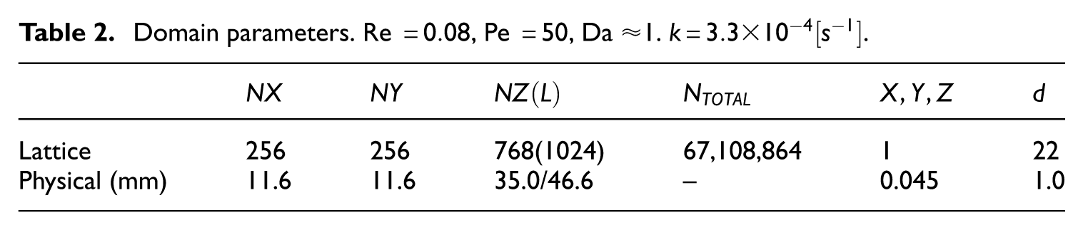
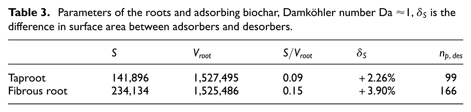
Table 3 displays the root morphological differences between the cases. Note that while volume is similar in both cases, the adsorbing surface area varies significantly. The number of desorbing particles
Parameters of the roots and adsorbing biochar, Damköhler number Da
Operating conditions
An initial concentration
The solute distribution evolves in a steady flow field with a Re
Model validation
Figure 3 displays the validation for flow between an array of periodic cubic centered spheres and includes a grid convergence study. For a complete validation of the passive scalar reactivity model, we refer the reader to the previous work by Maggiolo et al. (2023) which includes a full validation in the Appendix.
Flow validation: (a)
In Figure 3(a) we plot

the desorption/adsorption flux difference, where
where
Results and discussion
A qualitative representation of the dynamics within our system is shown in Figure 4; where the fibrous root is shown on the left (a), and the tap root on the right (b). The dimensionless concentration
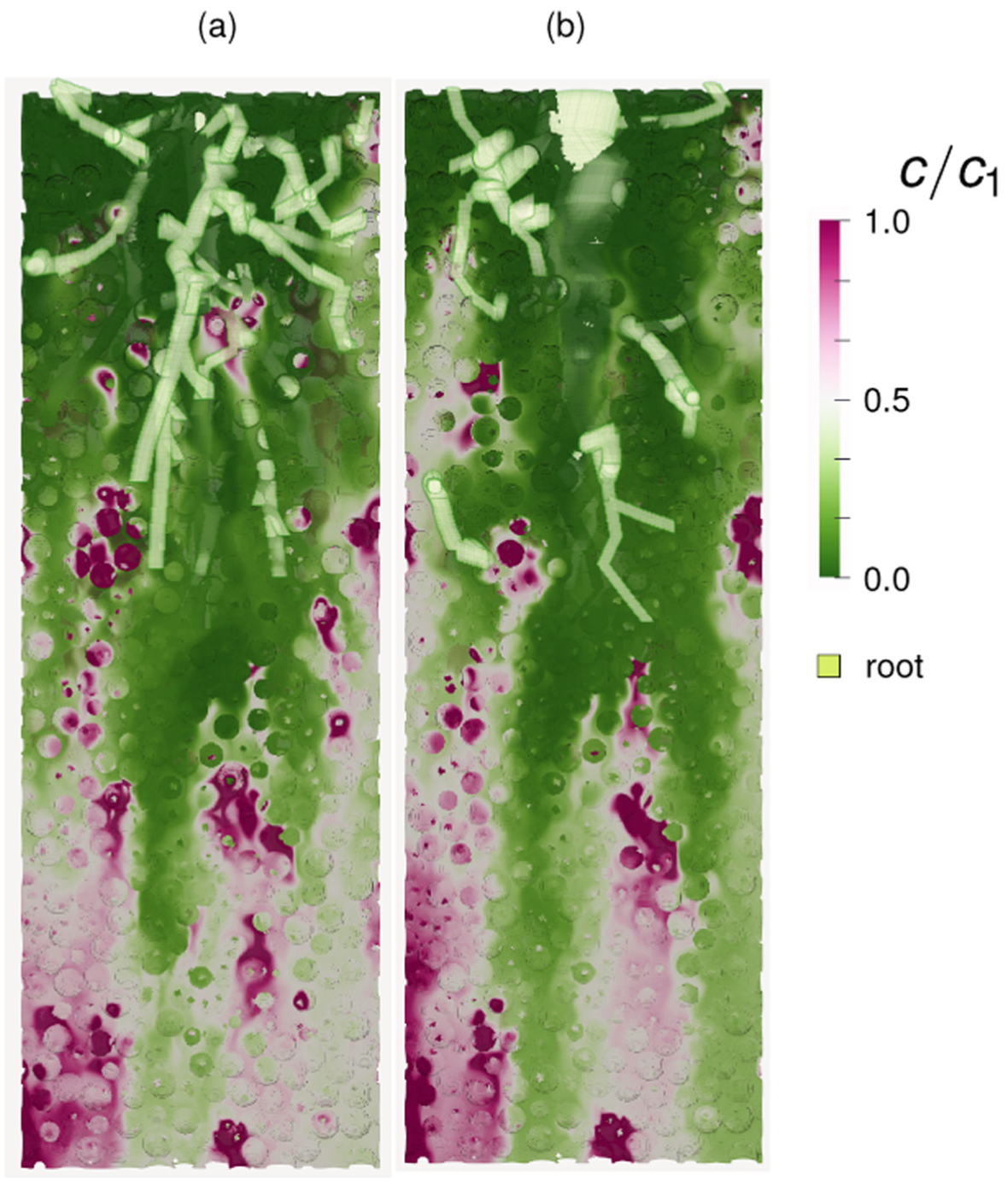
Root geometries: (a) fibrous root and (b) taproot. Dimensionless concentration
A more abrupt change (seen as a magenta/white border rather than a gradient from magenta to white, e.g.) signifies a high concentration gradient. In the tap root case (right panel) the magenta has a more gradual gradient and is more spread in terms of area, particularly in the longitudinal direction. We also note that longitudinal stretches of low concentration (denoted by the green plumes) are more visible for the tap root in this particular slice, implying the potential of more efficient solute removal in this case. These observations may be due to the location of some desorbing particles, which are likely responsible for localized pockets of higher concentration below the root structures. Another cause of these pockets is the presence of concentration plumes extending from the desorbers downstream. It is also the case that these plumes can coalesce, leading to larger areas of concentration at the outlet visible in both cases. A deeper analysis is necessary to determine what is occurring within the concentration field, particularly in relation to the location of the random particle desorbers and the plumes extending therefrom.
In order to quantify the existence of plumes, we examine the concentration differences in pores between the desorbing particles and the global mean value. By examining these fluctuation correlations we can determine if a pore upstream has an effect on those downstream, essentially the formation of a longitudinal plume. Figure 5 gives the average fluctuation correlations between the concentration in any given pair of pores within a prescribed downstream search angle
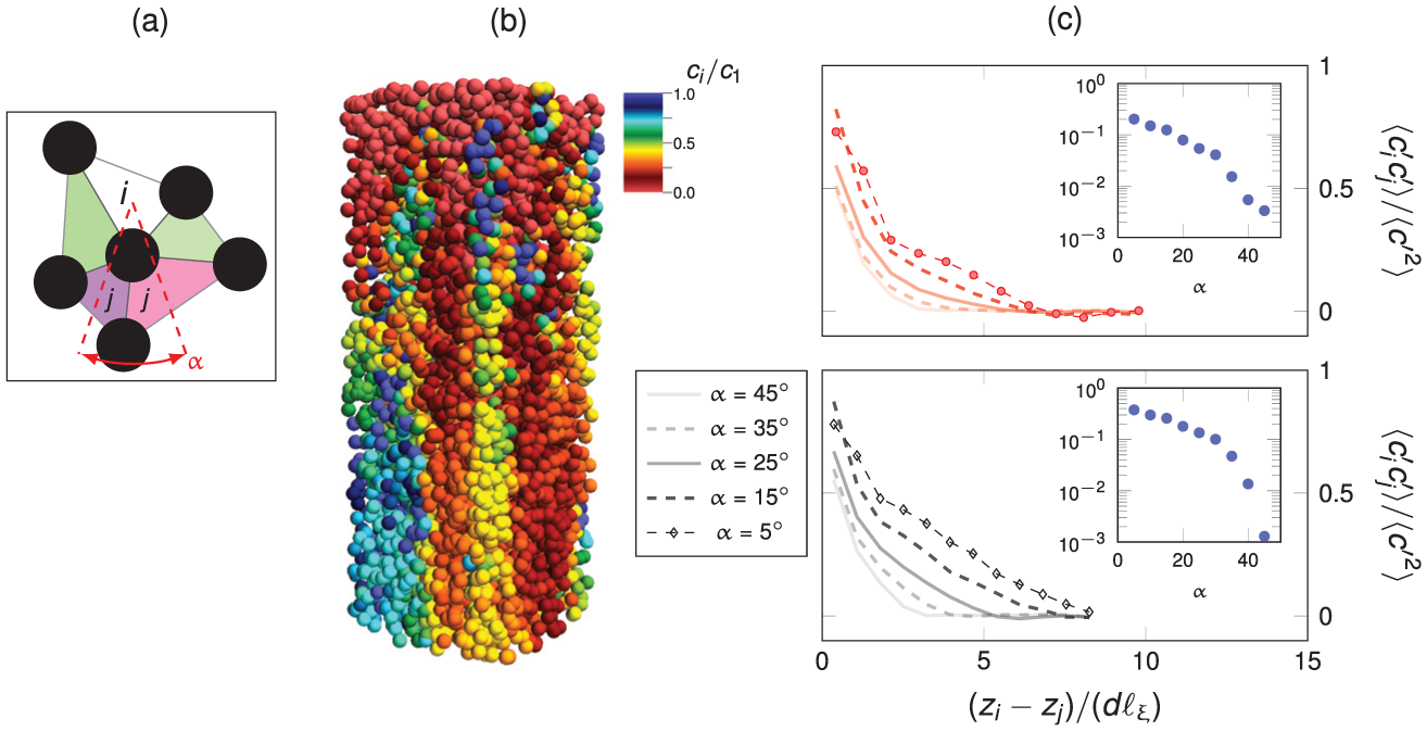
(a) Visualization of Delauney tesselation used to calculate the pores between desorbing particles.
In Figure 5(a) we see the partitioning of pores
Figure 5(c) quantifies the mean correlation of pore concentration, normalized by the variance, as a function of longitudinal distance between any two pores, as well as normalized by the average distance between desorbers. Several search angles are used, ranging from
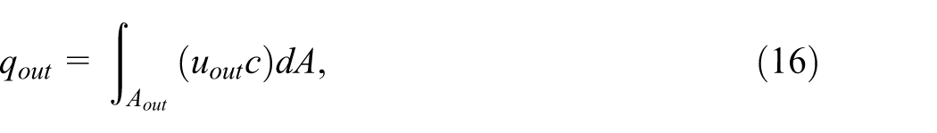
Figure 6 displays the probability distribution functions (PDFs) for three different locations within the domain. Figure 6(a) is calculated at the outlet over a small volume with depth of one particle diameter
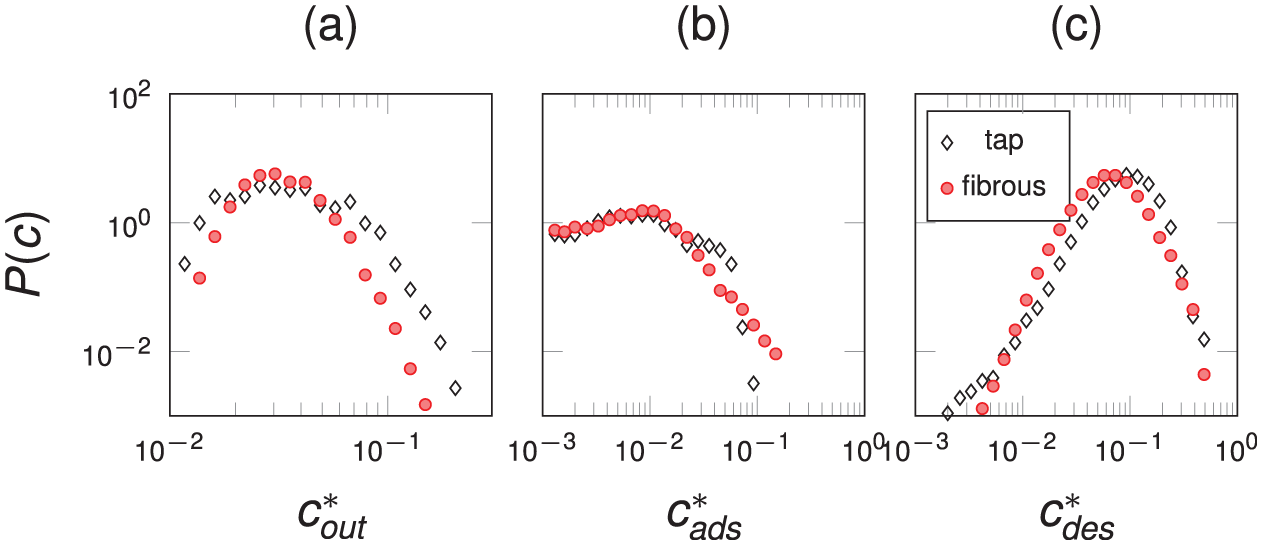
PDFs of normalized concentration at a small outlet volume (a), on the adsorber surface (b), and on the desorber surface (c). The tighter fibrous root curve in (a) implies a more homogeneous breakthrough front.
The surface behaviors for both cases are similar in Figure 6(b) and (c), with similar distribution curves. The concentration magnitudes also span the same range, though the peaks differ, with maxima at 0.01 and 0.1 for adsorbers and desorbers, respectively. Figure 6(a), however, shows a clear difference in the outlet concentration profile between the fibrous and tap roots. The fibrous root has a tighter curve, implying a more homogeneous outlet concentration front, or breakthrough. This would indicate plumes with similar concentration. Since Pe
In order to look at the plume spatial distribution and its contribution to the concentration distribution, the evolution of the normalized concentration variance as a function of depth in the porous medium is plotted in Figure 7.
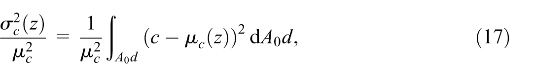
where
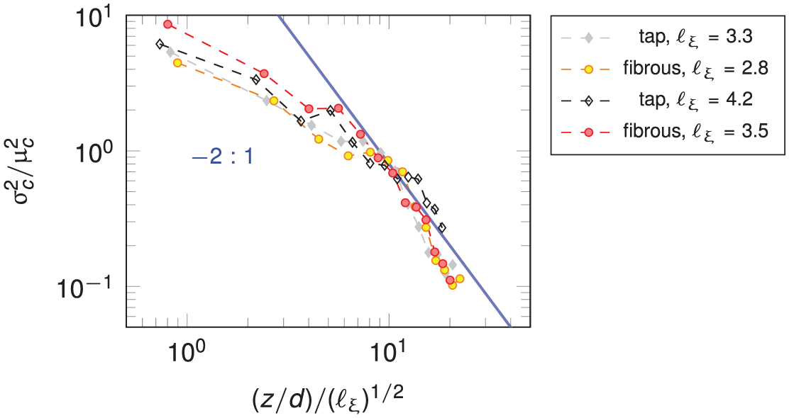
Normalized variance as a function of normalized depth. Blue line represents analytical relationship between the quantities.
We apply the random aggregation model (Duplat and Villermaux, 2008) to show how the overlap of plumes gives the relationship in Figure 7. This model states that you assume each concentration field in every plume to be identically distributed and that overlaps occur randomly in space. This allows for the calculation of the global variance as the variance obtained from the random sum of identically distributed concentrations; and as a consequence of the random plume overlaps.
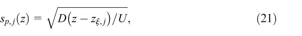
We start with defining that each plume diffuses in time and space such that its transverse spread

and in time

We can then define the ensemble average of the transversal spread of all plumes at a given depth
where
where we introduce the probability
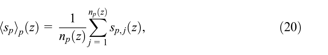
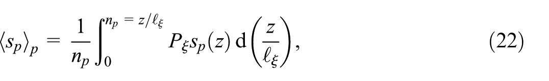
Utilizing our definition

Equation (22) is rewritten as
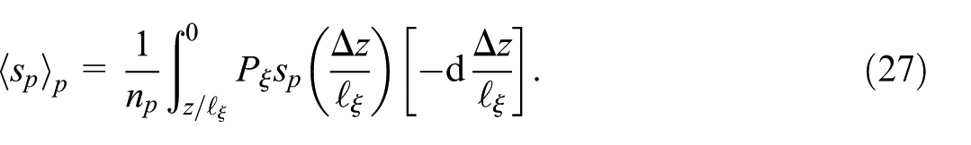
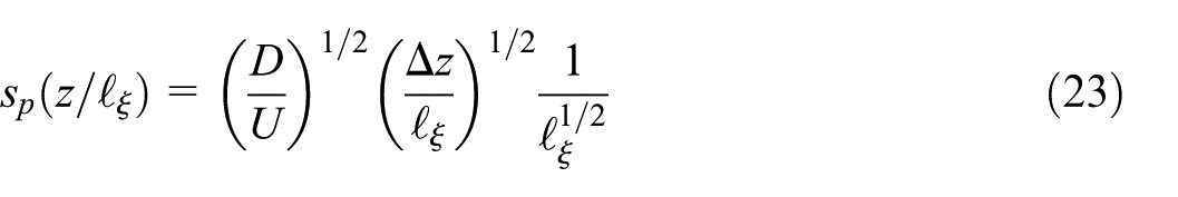
Finally, by combining equation (23) and rewriting the integral in equation (27) we can write the plume transversal spread ensemble average as
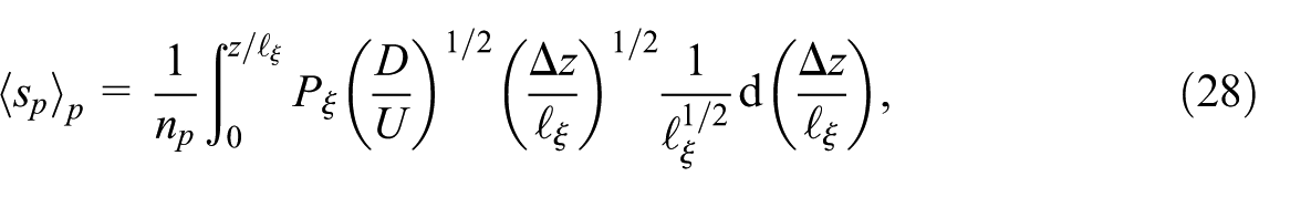
which is integrated over the number of plumes at a given depth
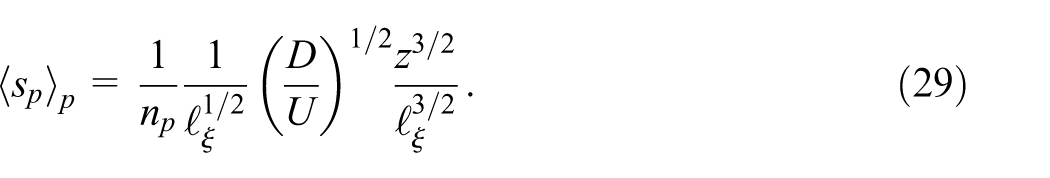
We model the blending of the plumes at a certain depth
and with a variance

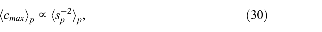
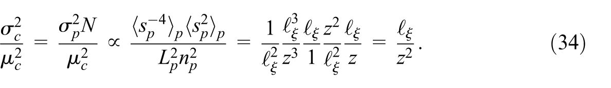
We expect the variance of a single isolated plume to approximately scale inversely with the square of the maximum concentration (Heyman et al., 2021), giving the relationship in equation (31). The mean transversal spacing between the plumes
The number of overlaps

As mentioned above, we assume that each plume’s concentration is described by a small, identical, Gaussian distribution when compared to the total physical volume in which the plume itself is located (Heyman et al., 2021). This is a very strong assumption, however it is extremely difficult to calculate a PDF for the plume structures we are attempting to isolate, thus we are forced to use a model that attempts to capture the PDF via aggregation of smaller, individual plumes. The random aggregation model states that the global variance is obtained from the random sum of identically distributed concentrations of randomly overlapping plumes, that is
The characterization above is valid when diffusion is the main mechanism for plume spread and when inertial effects are negligible such as with low Re. High values of Da can also invalidate this equation. A very low Da can lead to the possible occurrence of advective mixing, particularly for low concentration in high velocity pores, whereas a higher Da will serve to homogenize the concentration by suppressing mixing effects.
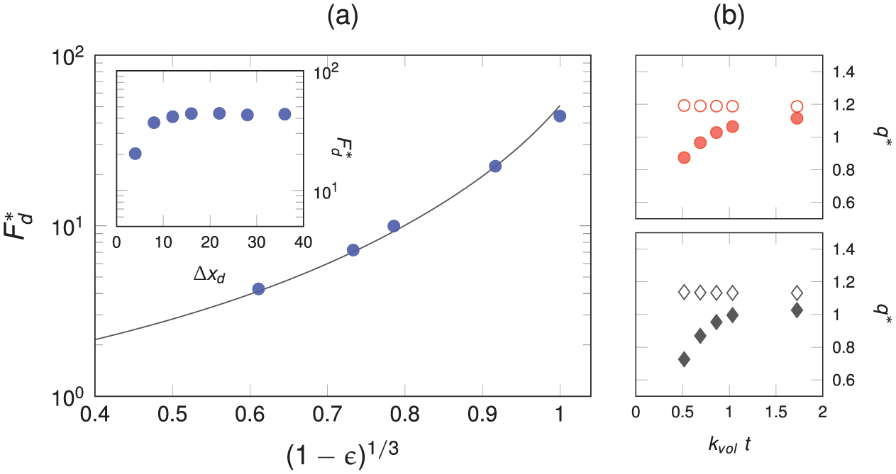
The blue line represents the analytical relationship between the moments of the PDF and the evolution of
In Figure 7 all cases scale very similarly to the analytical relationship between the moments of plumes as a function of depth when described as an aggregate of plumes with a given spread and overlap. The discrepancy at low
We have also varied
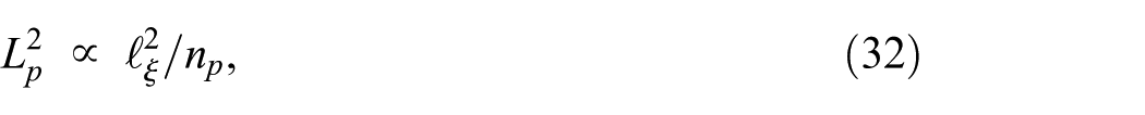
We can say that by prescribing the surface area of randomly distributed desorbing particles we effectively assign an average vertical packing distance
By increasing the number of desorbing particles we expect to have a more homogeneous mixing, with the concentration variance
Conclusions
This work proposes a methodology by which the interaction between different roots and the biochar desorbers within a soil substrate can be quantified. We have analyzed the adsorptive efficiency of two different root configurations under steady flow conditions corresponding to an extreme rainfall event by solving the advection-diffusion-reaction equation using the lattice Boltzmann method. An analysis of the fertilizer runoff is undertaken, with each root geometry varying the homogeneity of the breakthrough. It is shown that fibrous root structures act to homogenize the concentration breakthrough profiles to a greater degree than the tap root. An investigation of plume statistics and concentration fluctuations near the reactive particles shows that we can adequately characterize the evolution of the concentration profile as an overlap of plumes and a consequence of the root surface area. This relationship is quantified using a measure of the average distance between desorbing particles
If one applies this to a green roof design, there are several relevant lessons to be taken. Choice of plant type will have an impact on the breakthrough under heavy rainfall conditions. This is exacerbated if the green roof is thin, on the order of a few centimeters, such as extensive green roofs, which are typically around 5 cm thick and more common in practice due to their lower installation costs. If the designer chooses more fibrous root plants such as sedum or grasses they should expect to see more homogeneous breakthrough (a constant quantity of fertilizer being washed out) whereas if a taproot plant such as dandelion is used, the mean breakthrough will be lower but there may be events which have significantly higher peaks, potentially problematic given the lack of bespoke drainage systems attach to typical extensive green roof systems.
Alternatively. greater breakthrough homogeneity is achieved by adding more biochar, thus reducing the distance between each active element, however this will increase overall breakthrough magnitude and may even act to poison or damage the vegetation if too much fertilizer is adsorbed and subsequently released in a short period. Thus, there exists a maximum amount of biochar that should be added to any green roof. Our work included 10% biochar by volume, around the maximum distribution that remains safe for the plants, though this can be exceeded in certain circumstances, particularly if bespoke drainage systems are in place and/or the chosen plant type is accustomed to higher levels of fertilizer in the soil.
In general, it is more beneficial to have the biochar dispersed in closer proximity to the plant root structure, though of course the roots will grow to the nutrient source in time regardless. The plant adsorption will induce a greater solute gradient in proximity to the biochar desorbers, thus increasing the efficiency of the transfer irrespective of the flow velocity. An interesting design consideration can be taken from this; if one is concerned about root growth, one can incentivize them to grow in a particular direction by providing the nutrient source in a particular location, which can also act as a reservoir for any excess solute as well, preventing unnecessary contamination of the rainwater flowing through the roof.
This study focused on the impact of a singular root on the distribution of concentration within our domain. If one expands the domain or includes additional roots in close proximity, one would expect the total breakthrough to decrease, but not linearly, since the roots will compete for the desorbed “nutrients”. The authors looked into the effect of proximity between the adsorbing roots and desorbing particles, where it is known that plants will grow their roots to reduce the distance between the source of the nutrients and themselves. The concept of competition is certainly interesting, and to a degree, addressed in this work in the form of the fibrous root, where more root structures exist within close proximity to each other. As for neighboring root structures, it is more difficult. It has been pointed out that even within a singular root tendril there is heterogeneous root uptake, driven by entirely biological processes that are extremely difficult to predict. From a fundamentally mechanical/reactive perspective we expect the presence of additional root tendrils, be they from the same plant or a neighbor, will increase desorption by removing more of the solute from the system. If the roots are more spatially distributed, we should see a decrease in plume formation, as the solute will be removed faster and the roots systems will not grow in overlapping patterns, thus forcing the particles into closer proximity to the biochar, creating a more efficient transfer of the solute.
Footnotes
Ethical considerations
No ethical approval was required in this study.
Funding
The authors disclosed receipt of the following financial support for the research, authorship, and/or publication of this article: This work was supported by the Swedish National Infrastructure for Computing (SNIC) and the Swedish Research Council for Environment, Agricultural Sciences and Spatial Planning (FORMAS) [2019-01261, 2018-05973].
Declaration of conflicting interests
The authors declared no potential conflicts of interest with respect to the research, authorship, and/or publication of this article.
Data availability statement
The datasets generated during and/or analyzed during the current study are available from the corresponding author on reasonable request.*