
Abstract
The increasing energy consumption and detrimental CO2 emissions contributing to global warming underscore the urgent necessity for energy conservation, especially within buildings. Among different building components, fenestration plays a pivotal role as it accounts for the majority of heat transfer across the building envelope. This emphasises the significance of window-glazing technologies in enhancing their thermal performance. Furthermore, window-glazing systems can lead to overheating issues, particularly in summer, and glare issues, especially in winter. These challenges have spurred the development of various advanced glazing systems. This paper provides a comprehensive review of these advanced glazing technologies based on their functionalities and working principles, with a focus on parameters such as U-value, solar heat gain coefficient and visible transmittance. Among these technologies, vacuum and aerogel glazing systems exhibit superior thermal insulation properties, with U-values below 1 W/m2 K, making them suitable for heating-dominated climates. Smart window systems, such as electrochromic windows, are ideal for cooling-dominated climates due to their low solar heat gain coefficient (0.09–0.47) and visible transmittance (0.02–0.62). Photovoltaic window systems not only provide effective thermal insulation and solar shading but also produce additional power for on-site use. Some of these glazing systems feature complex structures, which present challenges when integrating them into existing building simulation software to assess their impact on building performance. Therefore, this paper also examines techniques for conducting energy and daylight performance simulations for buildings that make use of complex window systems. Ultimately, the authors propose an approach to characterise the thermal, optical and electrical properties of a complex photovoltaic window system within existing building simulation software, such as EnergyPlus. This approach facilitates a thorough investigation into the effects of complex window systems on building energy efficiency and indoor comfort.
Keywords
Introduction
The challenges and uncertainties confronting the global energy system, including increasing shortages and rising prices, are currently at their most significant level in nearly 50 years (BP, 2022). The building sector, recognised as one of the leading energy consumers worldwide, accounts for a significant portion of approximately 40% of total primary energy consumption in developed countries (Cao et al., 2016). Moreover, Greenhouse Gas (GHG) emissions resulting from the use of fossil fuels in buildings are a significant contributor to global warming (Wang et al., 2016b). Consequently, energy conservation and on-site renewable energy production have emerged as focal points in energy policies and decision-making processes for future building design (Bui et al., 2020; Chehab, 1994; van Roosmalen et al., 2021).
In comparison to other building envelopes, window systems serve multiple functions, including providing thermal insulation, sound insulation, daylight control, weather protection, fresh air supply and connection to the outside environment. Among these functionalities, thermal transmittance (also known as U-value), Solar Heat Gain Coefficient (SHGC) and Visible Transmittance (VT) are three key indicators that significantly impact the energy and daylight performance of a building.
The U-value, also known as total thermal transmittance or total heat transfer coefficient, of a building window indicates the heat loss or gain through it due to the temperature difference between the indoor and outdoor environments (Aguilar-Santana et al., 2020). Measured in W/m2 K, the U-value is determined by three well-known heat transfer mechanisms: conduction, convection and radiation (Aguilar-Santana et al., 2020), as depicted in Figure 1(a). The heat transfer through a double-glazed system between inside and outside of a building consists of the conductive (Kg) heat transfer through the glass panels, convective (hg) and radiative (Eg) heat transfer existing into the air cavity between two glass panes and convective (he and hi) and radiative (Ee and Ei) heat transfer between glass pane (outside and inside) surfaces and (outdoor and indoor) environments. Windows with lower U-values demonstrate better thermal insulation performance, and vice versa. Compared to other building components such as the floor (0.25 W/m2 K), roof (0.16 W/m2 K) and external wall (0.30 W/m2 K; Cuce, 2014), window systems tend to have notably high U-values (2.0 W/m2 K), resulting in a significant proportion (around 60%) of the total energy loss of a building (Cuce, 2018; Gustavsen et al., 2007; Jelle et al., 2012; Lee et al., 2013). Therefore, the development of windows with low thermal transmittance/U-value can make a substantial contribution to building energy savings.
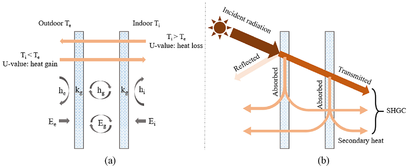
Heat transfer through a double-glazed system under the condition: (a) without solar radiation and (b) with solar radiation.
Solar Heat Gain Coefficient (SHGC), also known as g-value or solar factor, was defined by the fraction of external solar thermal energy that is admitted through a window, both directly transmitted and absorbed then released to inward (secondary heat; Marinoski et al., 2007) as shown in Figure 1(b). The SHGC of a window system is expressed by a ratio between 0 and 1. It depends not only on the material properties, such as the light transmittance and absorptance, but also on the indoor and outdoor environmental conditions, such as air temperature and wind speed. Typical SHGC values of the building window range from 0.2 to 0.7 (Aguilar-Santana et al., 2020). The lower a window’s SHCG, the less solar heat it transmits (Aguilar-Santana et al., 2020) and vice versa. A higher SHGC is important for reducing the heating loads in winter but will lead to the overheating issue in summer. Therefore, the choice of a glazing system with appropriate SHGC depends on different seasons, climates and locations.
Visible Transmittance (VT) is the visible part of the light spectrum that crosses a glazing system. It generally varies between 90% for a clear glazing and 10% for a highly reflective coated glazing (Aguilar-Santana et al., 2020). When the low visible glazing is used, the amount of visible light entering the space reduces. Since the daylight is blocked, the luminance level may be insufficient and the need of using artificial lighting may arise. On the other hand, when the high visible transmittance glazing is used, glare can happen due to extensive daylight. It is important to design appropriate glazing components to have optimum daylight (Gündoğdu and Cilasun Kunduraci, 2019).
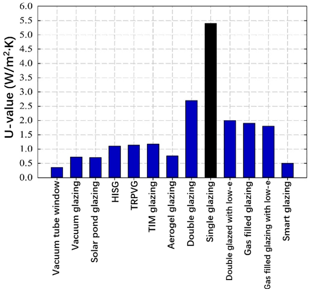
Based on the above analysis, a window system with a smaller U-value, along with reasonable Solar Heat Gain Coefficient (SHGC) and Visible Transmittance (VT), is beneficial for energy saving and indoor comfort. Traditional window systems often contribute to overheating problems during summer due to their high SHGC and U-value. Additionally, they can cause glare issues in winter because of their high VT and low solar incident angle. Accessory solar shading devices such as curtains or blinds are usually employed to deal with these issues. However, artificial lighting must be operated in the indoor space despite the high external light availability (Piccolo and Simone, 2015). To overcome these issues existing into the traditional window systems, innovated glazing technologies have been widely developed (Akram et al., 2021). Numerous researchers have examined the progress in window technologies over the last decade, as detailed in Table 1. To ensure that the articles in Table 1 represent recent advancements in fenestration technologies, only those published in or after 2012 were included. Moreover, only comprehensive papers focussing on various advanced fenestration systems were selected for Table 1, while review studies that specifically targeted particular systems, such as thermochromic and electrochromic smart windows (Wu et al., 2023), were excluded. For instance, some researchers (Aguilar-Santana et al., 2020; Cuce and Riffat, 2015; Jelle et al., 2012) conducted reviews of available high-performance glazing products and technologies. They all noted the growing popularity of vacuum glazing and aerogel solutions, which offer competitive U-values. Rezaei et al. (2017) also reviewed various types of glass coatings and glazing systems, including conventional, advanced and smart and analysed their applications in hot, cool and temperate climates. The results showed that the smart technologies are suitable for hot climate due to their low VT and SHGC values. Recently, Shum and Zhong (2023) have explored the fenestration technologies most suitable for cold climate applications. The results indicated that automated shading systems utilising insulative shading materials were most suitable for deployment in cold climate zones. Gorgolis and Karamanis (2016) reviewed different solar energy materials for window-glazing technologies, including insulating, reflecting, electrochromic, thermochromic, photovoltaic, water flow-based and emerging innovative materials. And the results indicated that glazing integrated PVs, are among the most promising solutions due to heating and cooling savings in addition to electricity production. There are also other reviews specified for the multi-glazing windows (Huang et al., 2021b), smart window (Mustafa et al., 2023), BIPV window (Ghosh, 2022; Mohammad et al., 2023; Yu et al., 2021) as well as the window with scattering (haze) properties (Ghosh, 2023). Feng et al. (2021) reviewed design methods for these high performance fenestration systems and Sun et al. (2018b, 2018c) put forward the method for characterising the thermal and optical properties of these complex window systems, as well as comprehensive building simulation approaches.
Summary of recent review papers (2012–2024) on fenestration technologies and treatments.
Although significant literature reviews have been performed in the area of glazing technologies used for building envelope façades, the majority of them have categorised these high-performance glazing technologies based on criteria such as static/dynamic, conventional/advanced/smart or emerging/established. For instance, many researchers have reviewed advancements in window technologies using static/dynamic window criteria (Aguilar-Santana et al., 2020; Ghosh and Norton, 2018; Hee et al., 2015; Michael et al., 2023; Zhang et al., 2023). Static windows, representing traditional designs, lack the capability to alter their properties in response to external factors and maintain fixed optical and thermal characteristics like U-value, VT or SHGC (Hee et al., 2015). Examples of static window technologies include multi-pane glazing, tinted glazing, low-E glazing, anti-reflective glazing, vacuum glazing, aerogel glazing, water flow glazing, air flow glazing, prismatic glazing and self-cleaning glazing. Dynamic windows, on the other hand, have the ability to adjust their properties based on external conditions or user input. These windows can change their transparency or insulation properties dynamically to optimise energy efficiency, comfort or privacy. Examples of dynamic window technologies include electrochromic, photochromic, thermochromic, gasochromic, phase change materials and liquid crystal devices. Although the classification of static and dynamic effectively covers most window systems, there remains debate about certain windows, such as PV windows, regarding their classification within the static or dynamic category. Some researchers (Ghosh, 2023; Ghosh and Norton, 2018; Michael et al., 2023) classified the PV window as static, as they cannot dynamically alter their thermal and optical properties. However, the PV glazing was also considered as the dynamic one due to their ability to actively generate electricity from sunlight, contributing to energy dynamics within a building environment (Aguilar-Santana et al., 2020). Therefore, relying solely on ‘static/dynamic’ to categorise all window systems may not always be comprehensive. In addition to static/dynamic classification, a more detailed categorisation distinguishes window systems as conventional/advanced/smart glazing technologies (Rezaei et al., 2017). Conventional glazing windows typically include basic designs such as single-pane or double-pane windows with standard framing materials like aluminium or wood. They may feature basic enhancements like tinted glass or reflective coatings to improve solar control, but they lack advanced technological features. Examples of conventional glazing windows include tinted glass, reflective glass and low-E coatings. Advanced glazing windows represent an intermediate level of technology between conventional and smart windows. These windows incorporate more advanced materials, coatings or construction techniques to enhance performance and energy efficiency. Examples of advanced glazing windows include aerogel, anti-reflective glazing, self-cleaning glazing and PV glazing. It can be seen the majority of the conventional and advanced windows are all static. Smart windows, a subset of dynamic windows, mainly include electrochromic, thermochromic, photochromic and liquid crystal technology. Furthermore, another study (Michael et al., 2023) classified glazing technologies based on their market establishment or under research and development. Despite the variety of classification methods, only a few studies have classified different advanced glazing technologies based on their functionalities or working principles, such as U-value, Solar Heat Gain Coefficient (SHGC) and Visible Transmittance (VT), as illustrated in (Ghosh and Norton, 2018). This is primarily due to the fact that these criteria are often incompatible or even conflicting with one another. For instance, increasing the thickness of tinted glass from 4 to 10 mm can reduce the U-value from 5.8 to 5.6 W/m K (Rezaei et al., 2017), thereby decreasing heat loss in winter. However, this change also results in a decrease in visible transmittance (VT) from 0.60 to 0.33 (Rezaei et al., 2017), potentially leading to insufficient indoor daylight. However, categorising fenestration systems based on their functionalities/working principles, particularly focussing on metrics such as U-value, SHGC, VT and the ability of power generation, offers several benefits:
Optimised energy efficiency
By focussing on glazing technologies to reduce the U-value, buildings can better retain heat especially in some colder climates and reduce the need for heating, leading to energy savings. Examples of such window technologies include vacuum glazing-based technologies (Fang et al., 2007; Manz et al., 2006) and aerogel glazing-based technologies (Michael et al., 2023). Jensen et al. (2004) developed a monolithic aerogel-based window integrated with vacuum glazing technology. The U-value of 0.66 W/m2 K was achieved for the evacuated glazing with a 13.5 mm thick aerogel layer (Baetens et al., 2011). Their study revealed significant energy savings potential, estimating a reduction of 1180 kWh/year (19%) by replacing triple-layered argon-filled glazing with aerogel glazing in a typical newly constructed single-family house within Denmark’s climate conditions (Schultz and Jensen, 2008).
Improved comfort and lighting control
Considering glazing technologies to regulate SHGC and VT allows for better control over heat gain and natural daylighting especially in some hotter climates. This can help maintain comfortable indoor temperatures while reducing the need for excessive cooling and artificial lighting, leading to energy savings and enhanced occupant comfort. For instance, Mesloub et al. (2022) conducted a study to evaluate the overall energy and daylight performance of an office equipped with a switchable Suspended Particle Device (SPD) smart window in a hot desert climate (Saudi Arabia, Riyadh). The Diva-for-Rhino and Energy-Plus simulation tools were employed to conduct building energy and daylight simulations at different orientations. The SHGC and VT of the window can be adjusted from 0.38 and 55% (ON state) to 0.05 and 5% (OFF state) respectively. Their findings revealed that the switchable SPD smart windows, particularly when in the OFF and automated states, demonstrated a promising reduction of net energy consumption by up to 58% compared to DG low-e windows, with the exception of the northern orientation. Additionally, these smart windows offered a significant decrease in daylight glare probability (DGP).
Integration of renewable energy
exploring glazing technologies capable of generating renewable energy, such as BIPV windows, offers the potential to offset building energy consumption and contribute to sustainability goals. Numerous studies have investigated the impact of BIPV window on building loads and energy consumption to assess their potential for energy savings (Chen et al., 2024; El Samanoudy et al., 2024; Hyun et al., 2022; Mohammad et al., 2023; Yu et al., 2021). For example, Mohammad et al. (2023) conducted a review on the energy-saving potential of various BIPV window technologies and their performance across different Köppen climates. The BIPV window types studied include single-glazed BIPV, non-ventilated double-glazed BIPV, ventilated double-glazed BIPV and vacuum-glazed BIPV. Their findings suggest that BIPV windows offer promising prospects for achieving Zero Energy Buildings (ZEBs) in the future. However, further research is needed to enhance the adaptability of BIPV windows to different Köppen climates. Moreover, the study highlights that vacuum-glazed and ventilated BIPV windows exhibit notable energy savings compared to other BIPV technologies and conventional windows, attributed to minimal energy losses due to vacuum insulation and optimal photovoltaic performance facilitated by ventilation.
In summary, analysing window-glazing systems based on their functionalities/working principles allows for the selection and integration of technologies that collectively enhance energy efficiency, occupant comfort and sustainability in buildings. Therefore, this paper reviews recent advancements in window-glazing technologies, focussing on their U-value, SHGC and VT, and examines methods for predicting the combined thermal, daylight and energy behaviour of buildings utilising these advanced window systems. The paper is structured into six sections. In Section 2, a review of window-glazing technologies aimed at reducing the U-value or improving thermal insulation properties is presented. These technologies mainly include the use of multiple panes, inert gas filling and vacuum glazing, etc. Section 3 discusses technologies for regulating solar and daylight penetration control, such as tinted coatings, reflective coatings and smart glazing technologies like thermochromics, electrochromics and gasochromics, etc. In Section 4, PV glazing technologies are explored, offering the additional advantage of generating electricity compared to other glazing technologies. Innovative PV glazing systems with optical components have gained significant attention in academia recently. These systems offer various advantages over conventional flat counterparts, including higher PV conversion efficiency, reduced use of toxic materials in the PV cells’ production process and improved indoor luminance environment (Chemisana, 2011). A review of CPV glazing technologies can be found in Section 5. These advanced window systems often feature complex structures, posing challenges when integrating them into existing building simulation software to assess their energy-saving potential and indoor comfort. Therefore, in Section 6, an analysis of methods for predicting the performance of buildings with complex window systems is reviewed. Following this, the authors propose a comprehensive model to investigate the thermal, optical and electrical performance of window systems with complex structures and PV cells, as well as their impact on the daylight and energy performance of the buildings to which they are applied. Finally, Section 7 discusses the reviews from Sections 2 to 6 and provides suggestions for future development, while Section 8 concludes the paper.
Glazing technologies to reduce U-value
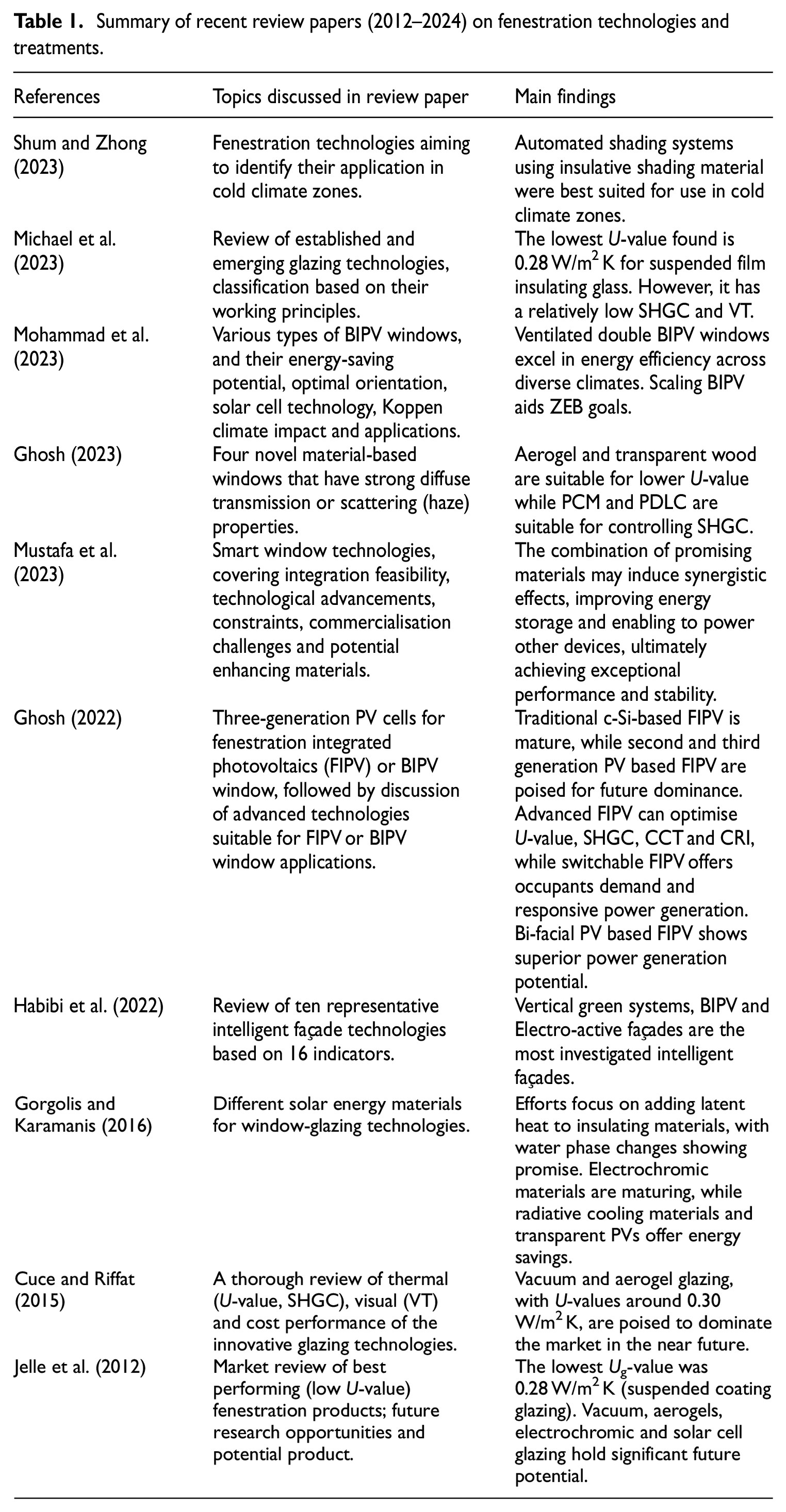
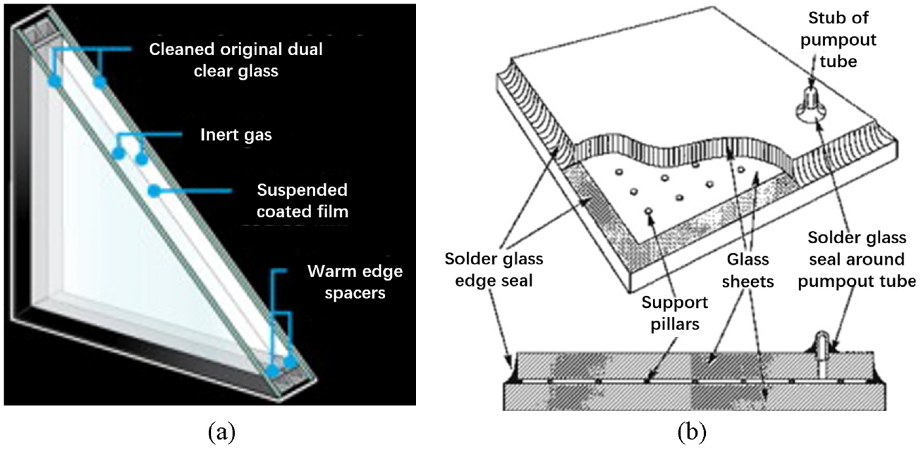
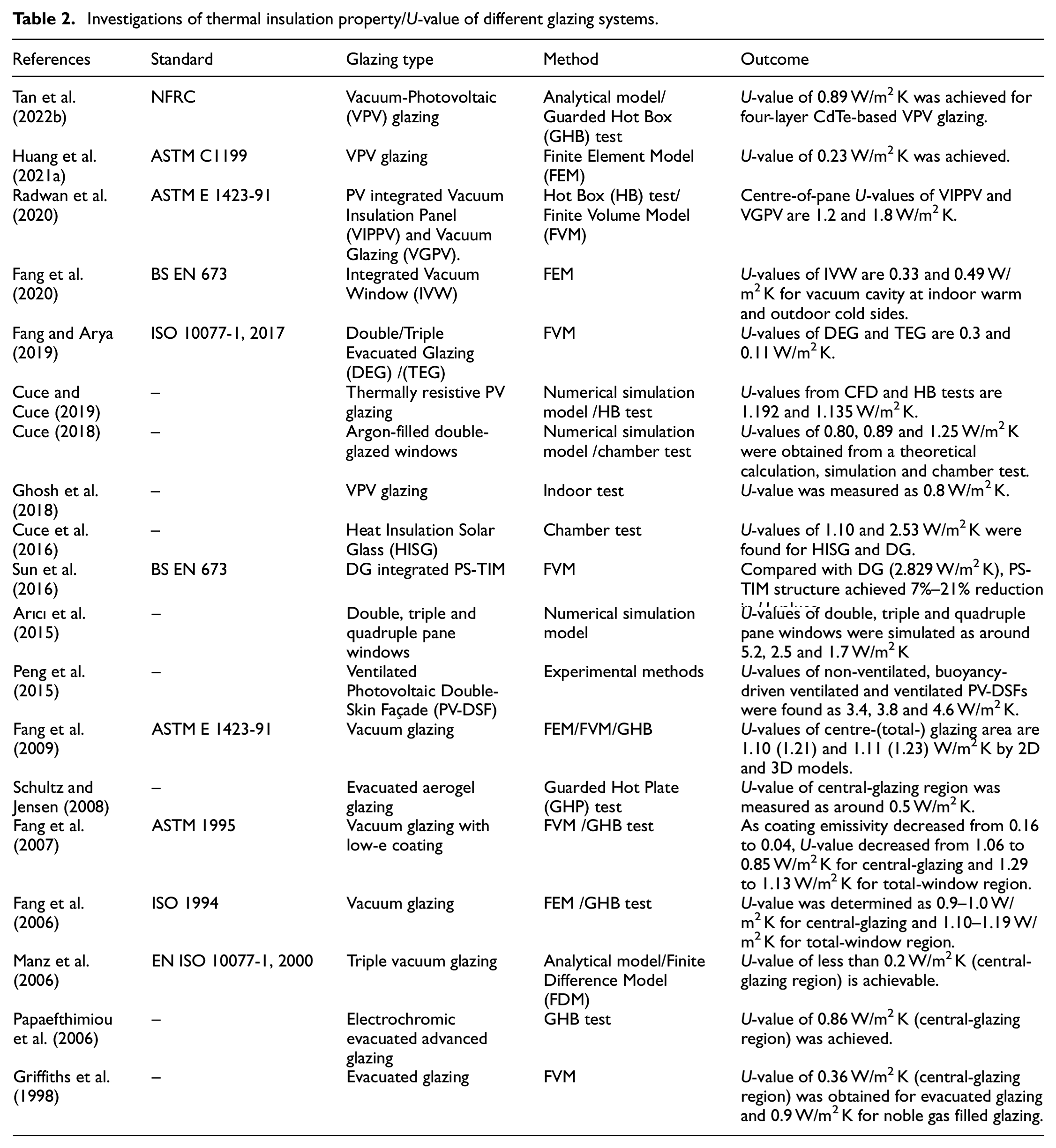
The thermal insulation property of the window system is important for building energy performance in both summer and winter. In summer, a smaller U-value reduces the heat exchange between air-conditioned indoor areas and the outdoor environment while in winter, it can reduce heat loss to the outdoor environment (Gorgolis and Karamanis, 2016). It was reported that the U-value of a double-glazed window is about half of that of the single-glazed window, which resulted in 39% to 53% energy saving by replacing single-glazed windows with double-glazed windows for commercial buildings in UK (Mortimer et al., 1998). To further reduce heat loss/gain through windows, there are several methods based on the double-glazed system, such as optimising the air layer thickness between two panes, filling the cavity between panes with an inert gas (such as argon), aerogel or insulation material, evacuating the cavity, coating pane surface with low emissivity materials, using multiple pane windows or simultaneously applying some of these methods (Arıcı et al., 2015). Jelle et al. (2012) listed the products in the market using these methods to improve its thermal insulation property. They found most high-performance products were triple glazed. A product of suspended coating glazing possesses the lowest U-value of 0.28 W/m2 K in the central-glazing region. The suspended coating glazing includes ‘Suspended Coated Films (SCF)’ or only ‘suspended films’ in between the exterior and interior glass panes, which acts as a third or fourth ‘glass pane’ as shown in Figure 2(a). Because films are thinner than glass, the use of these films can reduce the weight of the entire window compared to an ordinary multilayer glazing system. However, the transmitted ultraviolet and shortwave visible solar radiation may degrade suspended films, which affects its durability. The vacuum glazing consists of two sheets of glass separated by a narrow vacuum space with an array of supporting pillars holding the two sheets of glass separate (Jelle et al., 2012) as shown in Figure 2(b). The U-value of the vacuum glazing product on the market can reach 0.7 W/m2 K. Compared with the multilayer glazing system, the width of the vacuum glazing is narrower for same U-value. Akram et al. (2021) summarised the U-value of other glazing technologies in the market as shown in Figure 3. The research by Jelle et al. (2012) and Akram et al. (2021) provides valuable information about the thermal insulation properties of different glazing products. However, most of the data did not specify the methods and standards they referred to obtain these properties, which significantly affects the U-value results. Therefore, detailed information on the thermal insulation property/U-value of different glazing systems in academia, including the referred standards and methods is summarised in Table 2.
(a) Suspended coated glazing and (b) vacuum glazing.
Comparison of U-value of glazing technologies in the market (HISG means heat insulation solar glass and TRPVG means thermally resistive PV glazing).
Investigations of thermal insulation property/U-value of different glazing systems.
Glazing technologies to regulate SHGC and VT
In addition to U-value, window’s performance in terms of energy efficiency can also be assessed by looking at Solar Heat Gain Coefficient (SHGC; Jaber and Ajib, 2011). The U-value of the window glazing is always expected to be small to prevent the heat gain in summer and heat loss in winter. Unlike U-value, an appropriate SHGC for a window glazing system depends on different seasons, climates and locations. For example, a lower SHGC is important for reducing the cooling loads in summer but may increase the heating loads in winter. Therefore, the SHGC of window glazing is suggested to be larger than 0.6 and 0.5 under the cool and temperate climates, both with heating loads prevailing, while it is suggested to be smaller than 0.4 under the hot climate with cooling loads prevailing (Piccolo and Simone, 2015; Rezaei et al., 2017). In addition to ensuring that windows have proper SHGC, the VT also should be regulated to ensure the sufficient daylight but avoid glare.
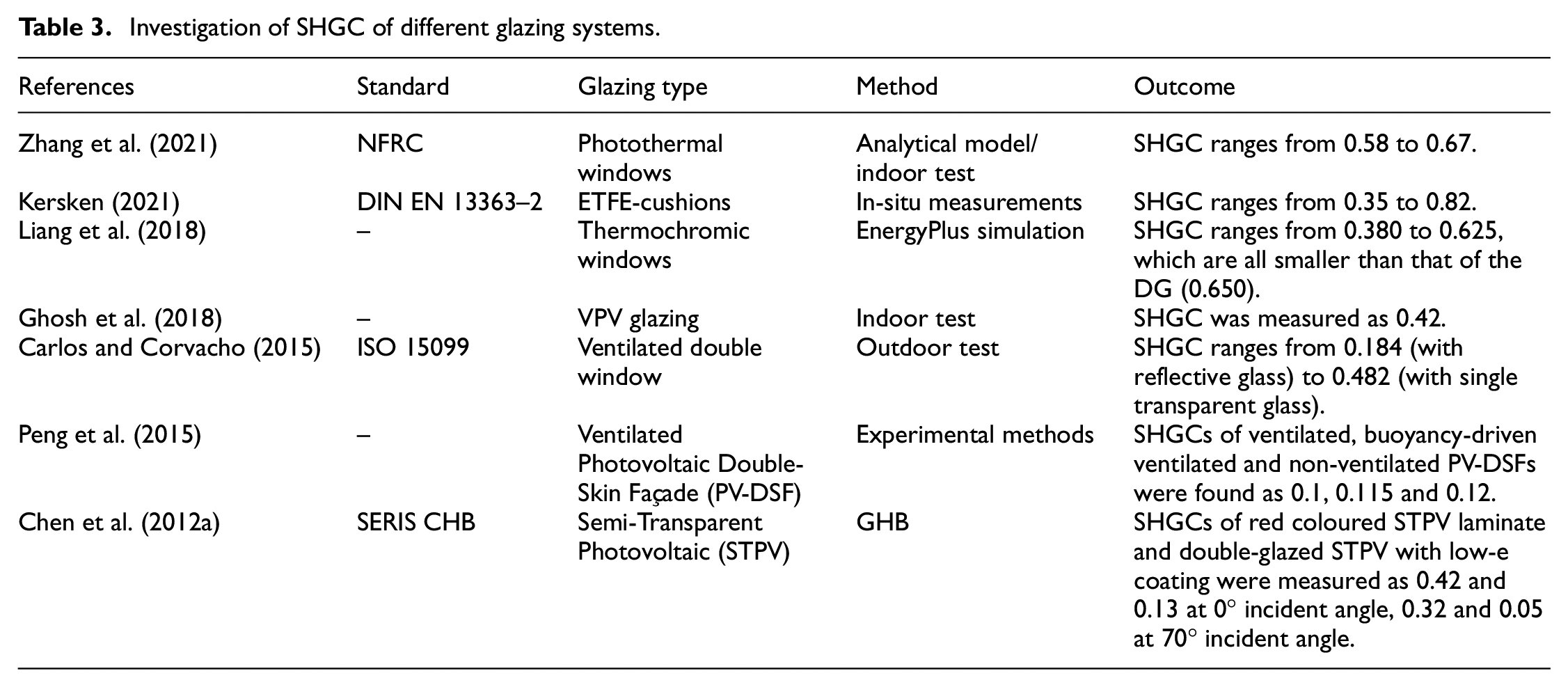
Typical single- and double-glazed (air filled) window have a SHGC value of 0.885 and 0.775, and VT of 0.901 and 0.817, respectively (Jaber and Ajib, 2011). To reduce the possibility of overheating and glare problems especially in hot climates, vast glazing technologies, such as reflective coating, solar control low-e coating and tinted glass with different colours have been developed. The colour of the tinted glass is determined by the ratio of the metallic colorants added during the floating process (Shcherbakova et al., 2001). It possesses a SHGC value from 0.45 to 0.68 and VT from 0.26 to 0.68 for different colours (bronze, green and grey) and thickness (4–10 mm; Rezaei et al., 2017). In addition to those designed to reduce SHGC and VT to prevent the overheating and glare, window glazing technologies were also designed to increase the SHGC to compensate the heating load especially in cold climates, such as passive low-e coating and anti-reflective coatings. The SHGC of a single glass with an anti-reflective coating can reach 0.90. However, the VT of 0.98 may cause glare. Even though the above glazing technologies are promoted in terms of its SHGC and VT based on single-/double-glazed systems, its properties cannot adapt to the changing weather conditions. The existing of the smart windows can solve the limitation of those static glazing systems. Smart glazing includes passive and active glazing technologies. The passive means the optical properties of glazing materials change when exposed to heat, such as thermochromic, photochromic and Phase Changing Materials (PCMs) based windows. The active means the optical properties of glazing materials are tuned using an external stimulus, including an electric field, heat or ion diffusion, such as the electrochromic and gasochromic. The SHGC and VT of the passive glazing, such as thermochromic glazing can be transited from 0.29 and 0.50 at 25°C to 0.13 and 0.12 at 65°C (Rezaei et al., 2017). For the active smart glazing, the electrochromic window can be switched from a clear state (0.47 SHGC and 0.62 VT) to fully tinted state (0.09 SHGC and 0.02 VT; Sbar et al., 2012). In addition to regulating the solar heat gain and visible transmittance, windows can also be employed to harvest energy, such as the PV glazing technologies. The SHGC of the commercial thin film PV glazing ranges from 0.123 (double-glazed unit with a-Si) to 0.413 (single-glazing laminate with µc-Si). However, the visible transmittance is extremely low (5%–8%; Ng and Mithraratne, 2014). Like the U-value, it is important to specify the standards and methods to obtain the SHGC value of window glazing systems. Table 3 lists the investigations of SHGC of different glazing systems, including the standards and methods referred to obtain it.
Investigation of SHGC of different glazing systems.
Semi-transparent photovoltaic (STPV) glazing technologies
The semi-transparent photovoltaic (STPV) glazing has a great potential to become part of the future glazing solution because of its high thermal resistance, being able to control the solar radiation as well as harvesting clean energy (Jelle et al., 2012; Wang et al., 2017). Examples of traditional STPV thus far integrated into building windows includes crystalline silicon (c-Si) solar cells (Peng et al., 2019), thin film solar cells (e. amorphous silicon (a-Si); Liu et al., 2020; Miyazaki et al., 2005), cadmium telluride (CdTe; Sun et al., 2019, 2020), Dye-Sensitised Solar Cells (DSSC; Selvaraj et al., 2019; Ren et al., 2023) and Organic Solar Cells (OSC; Anctil et al., 2020; Figure 4).
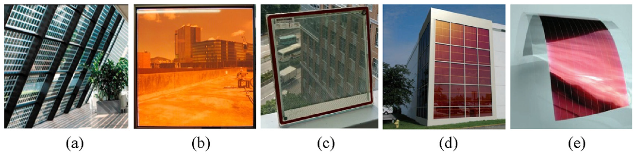
Different types of PV cells application on window glazing systems: (a) c-Si, (b) a-Si, (c) CdTe, (d) DSSC and (e) OSC.
Several review studies have been conducted to summarise the STPV products on the market as well as its properties. For example, Bizzarri et al. (2011) reviewed and classified the STPV products as three groups (matrix semi-transparency, process-induced semi-transparency and intrinsic semi-transparency) based on the specific photovoltaic material and the manufacturing process to achieve the semi-transparency. The matrix semi-transparent was achieved by creating a layout of opaque-transparent sequence using traditional crystalline cells. Process-induced semi-transparency means that part of the semiconductor substrate is removed using a laser-cut, which creates voids portions to allow visible light to pass through. It can be applied on amorphous silicon layers and crystalline silicon cells. The intrinsic semi-transparency means that the semiconductor materials have a physical/chemical property that makes them partially transparent, such as the dye-sensitised solar cell and organic polymer-based cell. Among these different PV cells, the crystalline cell has the highest PV efficiency, reaching up to 26.1% (National Renewable Energy Laboratory [NREL], 2022). However, the layout of the opaque-transparent sequence on the PV glazing may cast shadow inside the room (Sun et al., 2018a). The glazing integrated with amorphous solar cells (Curcija et al., 2021; Peng et al., 2015), CdTe solar cells (Sun et al., 2018a), dye-sensitised solar cells (Selvaraj et al., 2019) and organic solar cells (Tak et al., 2017) can achieve a uniform semi-transmittance state for daylight. However, the PV efficiency of these cells tends to be lower, with amorphous solar cells at 14.0%, CdTe solar cells at 22.1%, dye-sensitised solar cells at 13.0% and organic solar cells at 18.2% (NREL, 2022). Shukla et al. (2017) reviewed the existing Building Integrated Photovoltaics (BIPV) and STPV technologies in the market. The electrical properties of the BIPV/STPV as well as the universal guidelines and test standards have been summarised. The life cycle assessment of BIPV/STPV products was reviewed by looking at Energy Payback Time (EPBT) and Greenhouse Gas (GHG) emissions. This review concluded that more work remains to be done to upgrade the efficiency of BIPV/STPV products, such as the using of concentrated photovoltaic and hybrid photovoltaic technologies.
Concentrating photovoltaics (CPV) glazing technologies
For window integration, concentrating photovoltaic (CPV) systems can offer various advantages over a conventional flat counterpart, such as higher PV conversion efficiency, reduced use of toxic materials in the PV cells’ production process as well as providing better indoor luminance environment (Chemisana, 2011). A typical CPV system consists of a solar cell and optical concentrator, which can collect and concentrate sunlight onto the smaller solar cell. This system can be installed either on the roof or on the building façade depending on its geometry concentration ratio (geometry concentration ratio, Cg, was defined as the ratio of the aperture area of the concentrator and the solar cell area (Wu et al., 2016)). The high concentration systems (Cg > 100) and medium concentration systems (10 < Cg < 100; such as point focus Fresnel systems (Chemisana, 2011) and linear Fresnel reflectors (Bayón-Cueli et al., 2020)) could potentially produce higher electric power per unit solar cell area. However, most of it needs to work with specially designed solar cells, complicated sun-tracking devices, as well as the cooling techniques to maximise the solar radiation collection (Tang and Liu, 2011). Those systems can be integrated into buildings by roofs, especially for the flat one (Chemisana, 2011).
For building façade/window integration, the CPV systems tend to be stationary with low concentration ratios (Cg < 10). Many studies have been carried out to design various stationary concentrators intended for building applications, such as flat reflector (Uematsu et al., 2001c), wedge prism (Maruyama and Osako, 1999), linear Fresnel lens (Tripanagnostopoulos et al., 2007) and Compound Parabolic Concentrator (CPC; Sellami and Mallick, 2013). Other low concentration systems are less used as a result of specific reasons (such as low efficiency, Husain et al., 2018) including: fluorescent/luminescent concentrator, quantum dot concentrator and holographic concentrator. The following sub-sections describe four types of CPV systems, which have great potentials to be integrated into building windows.
Wedge prism
A wedge-shaped concentrator as shown in Figure 5 is normally constructed with transparent materials with high refractive index. A mirror is located on the left side of the rear surface and the exit surface to which the solar cell is bonded is located on its right side. The light irradiates the front surface, and then refraction occurs. The light can incident on the exit surface and absorbed by PV cells directly, or is reflected from the mirrored rear surface towards the front surface at an angle larger than the critical angle (critical angle was defined as the angle of incidence that provides an angle of refraction of 90°) for Total Internal Reflection (TIR; Maruyama and Osako, 1999). Study in Uematsu et al. (2001b) showed that the tilt angle of the rear reflector (θ) can affect the geometry concentration ratio (Cg), optical efficiency (ηop) and effective/optical concentration ratio (Cop) of the wedge-shaped concentrator. The optical efficiency (ηop) was defined as the ratio of the total solar energy (W) incident on the solar cell to the total incident solar energy on the concentrator entry aperture. While the effective/optical concentration ratio (Cop) was defined as the ratio between the intensity of rays incident on the PV cell (W/m2) to that of the rays incident on a plane having the same area and same orientation located outside the concentrator (Wu et al., 2016). It can be expressed as the geometric concentration ratio (Cg = A/A0) multiplied by the optical efficiency (ηop) as shown in equation (1).

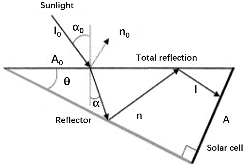
Wedge-shaped concentrator.
Uematsu et al. (2001b) proposed a Prism-Array-Concentrator (PAC) module as shown in Figure 6. The individual concentrator consists of a prism made of a transparent medium, a reflective sheet on the bottom slant and a solar cell on the other slant. The prism concentrators are placed under a 3.2 mm-thick cover glass. The ray-tracing simulation results showed that 94.4% of the annual irradiation can be collected by a PAC module with a prism angle of 32° and geometry concentration ratio of 1.88. When the prism angle was reduced to 22° (Cg = 2.66), the annual optical efficiency decreased to 66.2%. However, by using a V-groove reflector, the annual optical efficiency of 89.1% can be obtained with the same prism angle (22°). The maximum optical efficiency values of 82% and 81.7%, which correspond to optical concentration ratios of 2.18 and 2.17, were obtained for the fabricated PAC modules with a flat reflector and V-groove reflector, respectively.
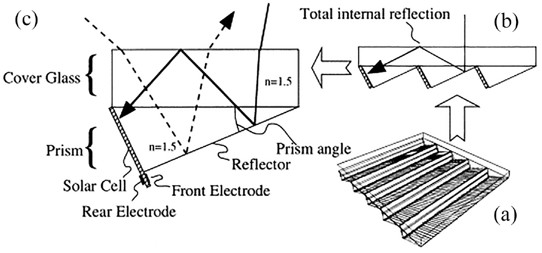
Schematic diagrams of (a) a PAC module, (b) the cross section and (c) unit concentrator.
A see-through prism CPV module for window integrated photovoltaic can be found in (Yamada et al., 2011). Figure 7(a) shows the cross-section view of this prism CPV module for illustrating its working principle. This module differs from previous studies in that there is no reflective coating on the facet AB. The direct solar radiation can be concentrated onto solar cells through TIR when the incident angle (θin) satisfies equation (2) while the diffuse part can be transmitted to the indoor space for daylight. This module generated approximately 1.15 more power than a conventional module while operating with 63% less surface area of solar cells.

Where,
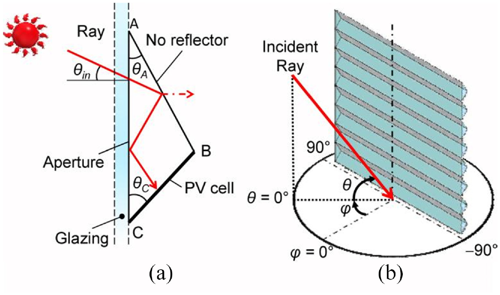
(a) Cross-section of the module and working principles and (b) coordinate system for the ray-tracing analysis.
Flat-plate reflector
Compared with a wedge-shaped concentrator, the structure of a Flat-Plate Static Concentrator (FPSC) is more compact. A FPSC PV module normally consists of a V-grooved reflector sheet, one or two sheets of flat-plate glass and monofacial or bifacial solar cells as shown in Figure 8. The only additional material is the V-grooved reflector sheet when compared with the conventional flat PV modules. Therefore, the FPSC PV modules could be assembled using conventional equipment. Uematsu et al. (2001a, 2001c) investigated these two types of FPSC with monofacial-cell (Cg = 1.5) and bifacial-cell (Cg = 2.0). Figure 8(a) shows that the light reflected by the V-grooves is completely reflected at the front glass surface and then reaches the solar cells through TIR. There is another glass sheet on the rear surface for a bifacial-cell-type FPSC module (Figure 8(b)). Two types of FPSC PV modules can both collect about 90% of the annual irradiation at the latitude of Tokyo. The optical efficiencies of 87.6% and 85.6% and optical concentration ratios of 1.31 and 1.71 were obtained for monofacial-cell-type and bifacial-cell-type FPSC modules, respectively.
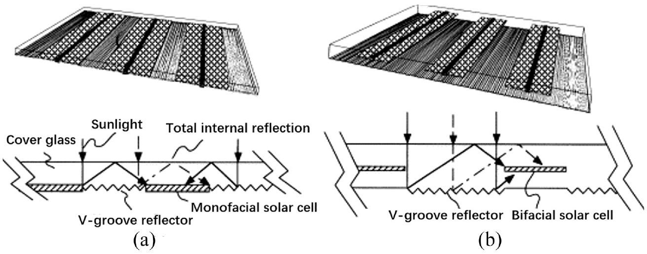
Schematic diagrams of FPSC modules with (a) monofacial-cells and (b) bifacial-cells.
Yoshioka et al. (2003) further improved the design of the rear v-groove reflector through optimising the optical performance of a monofacial-cell-type FPSC module under different geometry concentration ratios and reflective materials. The results showed that with the increase of the geometry concentration ratio from 1.5 to 2.0, the optical efficiency decreased from 0.84 to 0.71 while the effective concentration ratio increased from 1.27 to 1.43. There was a slight improvement of the optical performance for module with Ag-coated reflectors (94% reflectivity) than the one with Al-coated reflector (80% reflectivity). However, the deposition of Ag was not uniform over the reflective sheet and better optical performance was predicted using Ag-coated reflector. Koizumi et al. (2003) designed a new asymmetric V-groove structure at the rear surface as shown in Figure 9 to improve the performance of the FPSC PV module. The shape of the asymmetric V-groove was optimised at a: b = 4: 6 and θ = 25°. The PV coverage ratio (PV coverage ratio was defined as the ratio between the overall solar cell area and the total module aperture area) of the new module could be reduced to 98% compared with the previous developed module with symmetric V-groove and 74% compared with a conventional flat PV module.
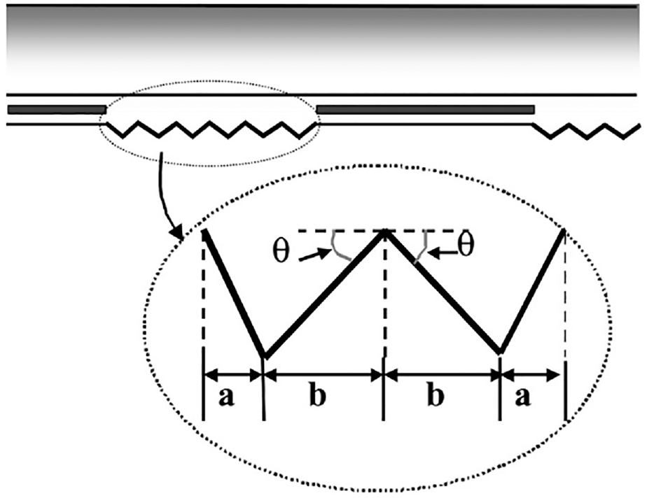
A new asymmetric V-groove structure.
Weber et al. (2004, 2006) developed a FPSC incorporating narrow (1–2 mm), bifacial cells and a lambertian reflector as shown in Figure 10. The reflected solar rays from the lambertian reflector can be absorbed by PV cells directly or reach the front surface of the module then incident on PV cells through TIR. Unlike the other FPSC modules with v-groove reflectors, the performance of this kind of module is insensitive to module orientation. In addition, the module with a geometry concentration ratio of 2 (50% PV coverage ratio) and 70 µm-thick cells can capture up to 84% of the light entering the module around the year.
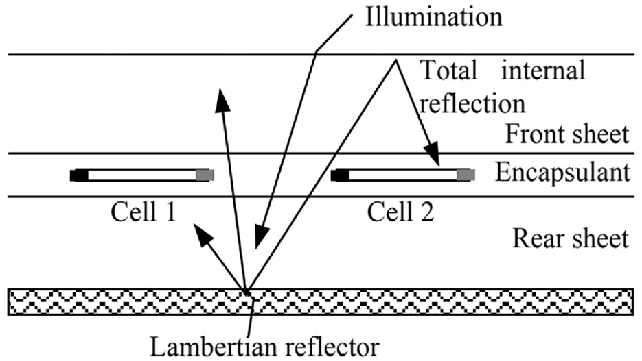
Structure of a module incorporating narrow, bifacial cells and a lambertian reflector.
The optical efficiency of the FPSC tends to decrease with the increase of the geometric concentration ratio due to the increased optical loss by light escaping from the top surface of the concentrator after each reflection from the back diffused surface (Kim and Dutta, 2012). To obtain high optical efficiency and effective concentration ratio simultaneously, Kim and Dutta (2012) designed four planar stationary concentrator PV systems and found the module with 40× geometry concentration ratio produced the highest effective concentration ratio (12×). The optical efficiency and effective concentration ratio can be further improved by the suitable roughness of the diffuser film.
A major problem associated with the FPSCs for window integration is their low transparency due to the use of highly reflective/scattering materials in order to achieve high optical efficiencies (Liu and Wu, 2022b). To solve this problem, several PV window systems were designed with transparent/semi-transparent flat reflectors and vertically located PV cells. For example, Chen et al. (2012b) designed a diffusive solar cell window as shown in Figure 11(a). It consists of a light diffusive plate (polycarbonate) sandwiched between two glass plates and solar cells located at the edges of the window. The highly reflective nanoparticles in the diffusive plate can scatter the light sideways towards the solar cells. With the increase of the haze (the amounts of nanoparticles) of the diffusive plate, the optical efficiency of the diffusive solar cell window increased while the light transmittance deceased. The window with 63.2% haze (62% transmittance) possesses a 1.27% efficiency and can produce 0.773 W electricity while the window with 40.7% haze (70% transmittance) possesses a 1.15% efficiency and can produce 0.661 W electricity under AM1.5 and global 1-sun solar illumination conditions. Morimoto and Maruyama (2005) proposed a static solar concentrator as shown in Figure 11(b). It consists of a white/transparent switchable bottom plate and vertical plate solar cells. The bottom plate is transparent when the cell does not provide power, and it is switched to be white (Lambertian surface) and reflects diffusely when the cell generates electricity. For the same PV coverage ratio, the optical efficiency for the proposed concentrator is about half of that of the FPSC module. Because of the white/transparent switchable property, this CPV module has great potentials to be integrated into building windows to control the solar radiation as well as power generation.
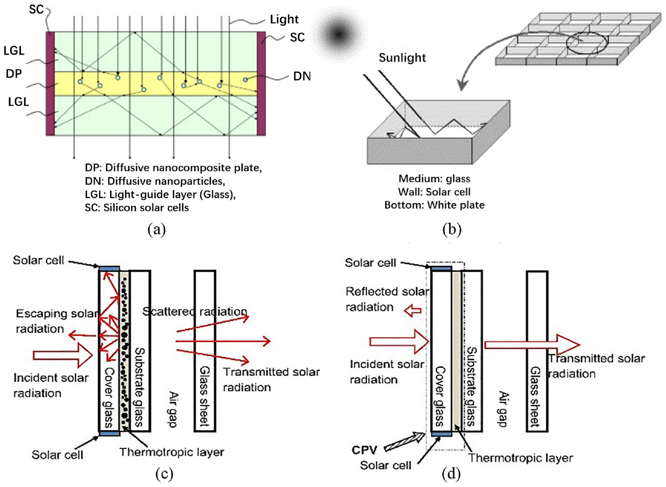
(a) Diffusive solar cell window (Chen et al., 2012b), (b) concentrator with vertical plate solar cell (Morimoto and Maruyama, 2005) and smart concentrating PV system in (c) summer and (d) winter (Wu et al., 2016).
The similar smart CPV system, which was designed for building façade/window integration, was proposed by Wu et al. (2016). This system includes laminating a hydrogel/polymer thermotropic (TC) coating with a conventional glass sheet. When the temperature of the TC layer is lower than the designed switching temperature, the layer appears transparent as shown in Figure 11(c). When the temperature of the TC layer is above the switching temperature, the TC layer becomes translucent with a diffuse reflectivity and a large proportion of scattered light from layer surface incidents on the edge coupled PV cells through TIR. The optical efficiency and effective concentration ratio of the system were estimated as 10% and 0.5, respectively, for the diffuse reflectivity of the TC layer being 50%.
Linear Fresnel lens
Fresnel lenses, which are made of transparent materials, are the most used for building application (Zhu et al., 2018). It includes two types based on its groove shapes as shown in Figure 12. When compared with the point focus one, the linear Fresnel lens, which can be designed small and compact, shows its potentials for integrating into window glazing systems. The use of a Fresnel lens as a transparent cover material for lighting and energy control of internal spaces was introduced in 1998 (Tripanagnostopoulos et al., 2007). It can concentrate the direct (beam) part of the solar radiation on an absorber surface to harvest electricity/heat energy. While the diffuse part was used to maintain a minimum illumination level for interior space (Tripanagnostopoulos et al., 2007).
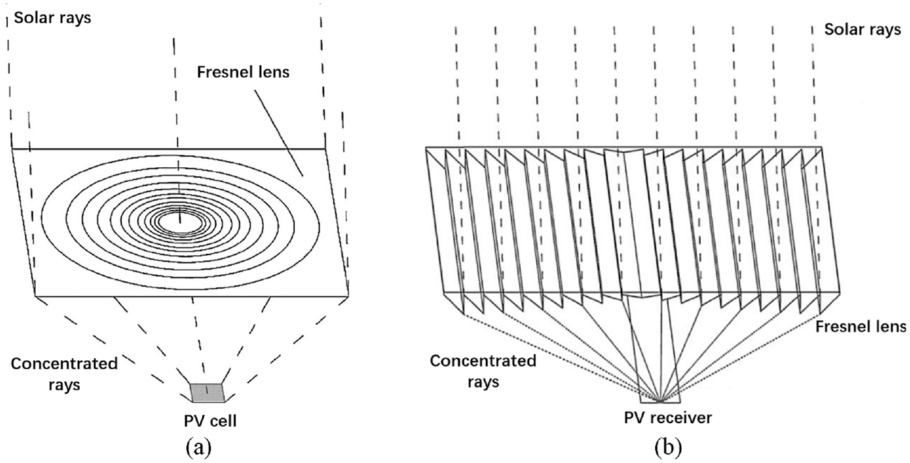
Schematic of a (a) point focus and (b) linear Fresnel lens.
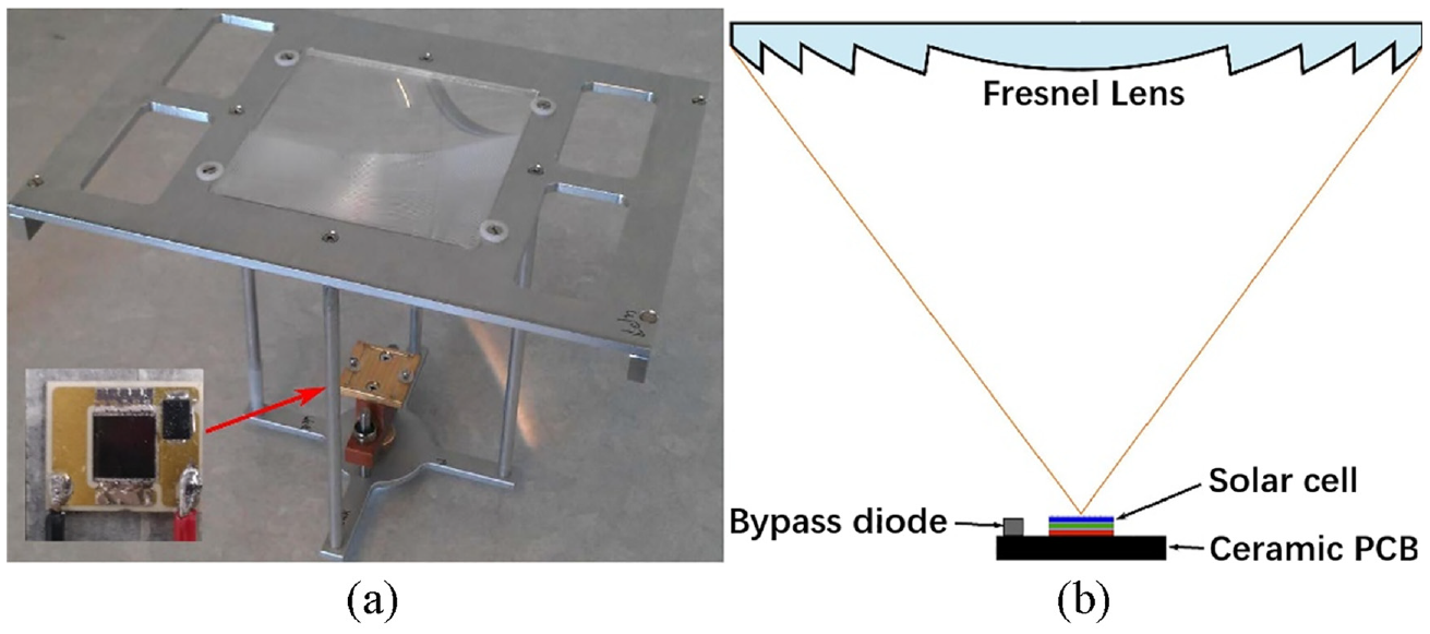
Tripanagnostopoulos et al. (2007) proposed the use of linear (glass) type Fresnel lenses (Cg = 2 and Ce = 1.6) combined with different absorber systems (thermal (T), photovoltaic (PV) or hybrid photovoltaic/thermal (PV/T)) for the illumination and temperature control of interior space. Figure 13(a) shows examples of Fresnel lenses application on the transparent cover of several buildings. A ‘test box’ as shown in Figure 13(b) was set up to measure the effect of Fresnel lens PV module (36 cm width, 56 cm length, 0.5 cm thickness and 34 cm focal length) on the reduction of the illumination and temperature level of the indoor space as well as estimation of the energy harvest from thermal or photovoltaic type absorbers. The results showed that 60%–80% of the transmitted radiation could be absorbed and used to cover the energy needs of buildings, leaving the rest of it used for illumination needs.
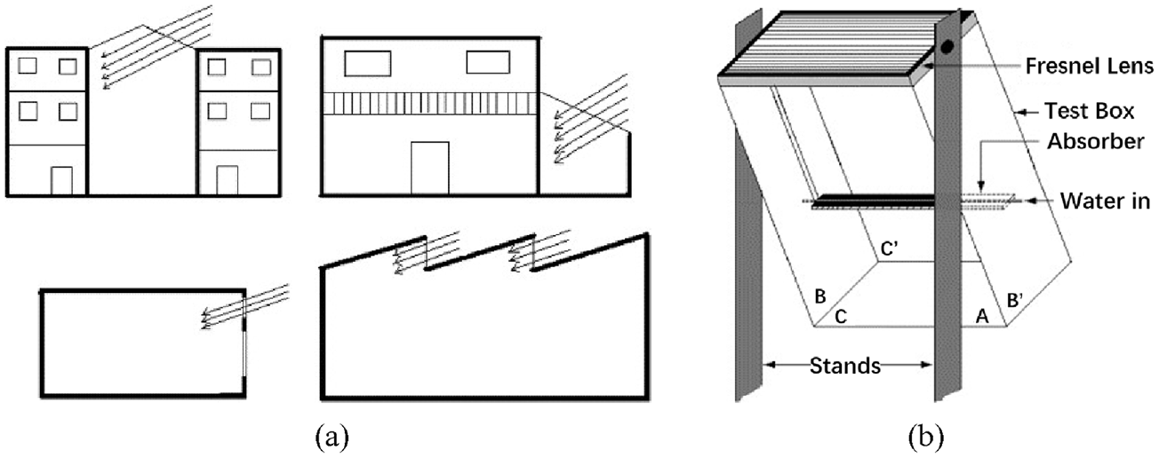
(a) Fresnel lens application on transparent covers of different buildings and (b) test-box with Fresnel lens.
Bunthof et al. (2016) investigated a semi-transparent building façade element constructed from a Fresnel lens based CPV (Figure 14). The geometry concentration ratio of the Fresnel lens is 100 and the focal depth is 10 cm. The effective concentration ratio was calculated as 62 based on the electrical test results (the short circuit currents of the CPV module and flat PV module were measured as 830 and 13.4 mA under 1-sun illumination).
(a) Fresnel lens based CPV and (b) structure of receiver integrated lens.
Zhu et al. (2018) designed a transmissive Fresnel concentrator for dynamic integration into building windows. It is a square Fresnel lens with dimensions of 150 mm (height) × 150 mm (length) × 3.1 mm (thickness). The focal depth is 145 mm and the geometry concentration ratio of the whole CPV module is 516. The overall optical efficiency was predicted as 78.68% at normal incidence, which indicates an effective concentration ratio of 406. In addition, dynamic control methods were designed to ensure sufficient indoor light under different weather conditions.
Compound parabolic concentrator (CPC)
Even though the concentration ratio of the liner Fresnel lens is much higher than that of the other static concentrators, it is always limited to window integration because of their addition optical focal depths. In addition, the optical performance is highly incident angle-dependent, which may not be perfect for window application. The compound parabolic concentrator (CPC) was said to be the most studied stationary and ideal low concentration optic for window application because of its higher optical efficiency and larger acceptance angle (acceptance angle was defined as the maximum incident angle for which transmission drops to 90% of its maximum (Ferrer-Rodríguez et al., 2018; Shanks et al., 2016; Tian et al., 2018). The first CPC, which was studied in the late 1960s, was impractical due to its considerable height (Li et al., 2020). Since then, many variations have been devised to achieve a more compact structure as well as larger acceptance angle and higher optical efficiency. These CPC optics can be classified as 2D-CPC (linear CPC/trough-like CPC, Bahaidarah et al., 2014) and 3D-CPC (revolved CPC, Cooper et al., 2013, crossed CPC, Sellami and Mallick, 2013 and lens-walled CPC, Guiqiang et al., 2013). A 2D and 3D-CPCs are symmetrical in original design with two equal half-acceptance angles. However, the evolution of the optical design has led to the asymmetric shape (Baig et al., 2013, 2014a; Lu et al., 2018; Sarmah et al., 2014; Sarmah and Mallick, 2015). Tian et al. (2018) presented a comprehensive and up to date review (since 2000) of the design principles, applications as well as the performance predictions for these different CPC optics.
Among different CPC variations, the Crossed Compound parabolic concentrator (CCPC) performs well in PV generation because it is created by the perpendicular intersection of two 2D CPC troughs (Sellami and Mallick, 2013). As illustrated in Figure 15, the geometry concentration ratio of the CCPC (3.6) is much higher than that of the 2D CPC (1.9). When compared with other 3D variations, it not only has the competitive concentration ratio and optical efficiency, but also an added advantage of having a square entry and exit aperture, which is convenient for combing with typically square cut PV cells (Cooper et al., 2013; Sellami and Mallick, 2013).
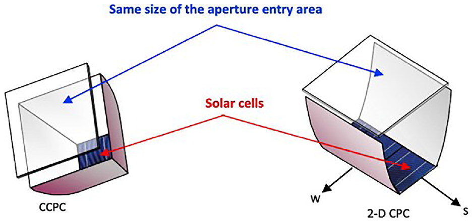
Comparison of 2D CPC and CCPC.
The CCPC can be classified as the reflective- and refractive-type. The refractive and reflective concentrators follow the principles of refraction and reflection of solar light from lenses or mirrors, respectively (Atheaya et al., 2017). The original studied CCPC is a reflective type. It is considered as a hollow concentrator and the side wall is made of highly reflective material or the material with high reflective coating, such as aluminium (Mallick et al., 2006) and gold-nickel mirror plating (Nakamaru et al., 2002). The refractive-type means filling a hollow concentrator with a transparent or semi-transparent dielectric material medium with refractive index larger than 1, such as the polyurethane (Sellami and Mallick, 2014), Topas (Polyolefin/Zeonex: COC Polymer; Sun et al., 2017b) and polycarbonate (Baig et al., 2014b). The optical efficiency of the refractive-type CCPC under normal solar radiation condition is lower than that of the reflective-type one because of the addition light absorption by the dielectric material medium. However, the acceptance angle of the refractive-type is larger than that of the reflective-type because of TIR (Sellami and Mallick, 2014). A larger acceptance angle is essential for a static concentrator to adapt different solar positions when applied to building façade.
As for the reflective-type CCPC-PV modules, Sellami and Mallick (2013) investigated its optical properties using 3D ray-tracing simulations, the results showed the maximum optical efficiency of 95% and half acceptance angle of 30°. In addition, the solar flux at the exit aperture was non-uniform distributed, which may consequently cause hot spots and decrease the efficiency of solar cells. Mammo et al. (2013) analysed its electrical properties based on MATLAB codes. The results showed that the maximum output power of the CCPC-PV module is three times higher than that of a non-concentrating PV counterpart. As for the refractive-type CCPC-PV module (Figure 16), Baig et al. (2014b) analysed the optical, electrical and thermal performance of a dielectric (clear polyurethane) based CCPC-PV unit through both experimental measurement and numerical simulation. The designed concentrator has a maximum optical efficiency of 73.4% and half acceptance angle of 34.5°. Figure 16(d) shows the light behaviours at different solar positions. A maximum power ratio of 2.67 was obtained when compared to a non-concentrating PV counterpart and the temperature distribution varied in the range of 297–332 K under normal incident angle condition as shown in Figure 16(c). They also analysed the effect of encapsulant spillage thickness on the optical losses incurred in the encapsulant interface between CCPC optics and PV cells using optical simulation. It was found that the optical efficiency of the CCPC-PV module decreased from 84.5% to 55.6% with the increase of the encapsulant spillage thickness from 0.1 to 3 mm. In addition, this optical loss could be eliminated by using reflective film along the bottom edge of the concentrator (Baig et al., 2015). Sellami and Mallick (2014) used polyurethane as the dielectric material for the CCPC optics. There was a sacrifice of 12% of optical efficiency when compared with the reflective one. However, the refractive CCPC can concentrate sunrays for a larger range of incident angles (-80°, +80°). Shanks et al. (2019a, 2019b) pointed out the weight is one of the constraints of CPV technology to hinder its applications in buildings. Therefore, the power to weight ratio of the CCPC-PV modules for optics made from glass and various plastic materials as shown in Figure 16(b) were investigated. Because the weight of the glass material is much higher than that of the plastic materials, the optic made from glass showed a higher power output (65.79 mW) but a lower power to weight ratio (6.32 mW/g). Topas (Polyolefin/Zeonex: COC Polymer) is the most suitable plastic material for refractive CPV optics, which possesses the highest power to weight ratio (12.21 mW/g).
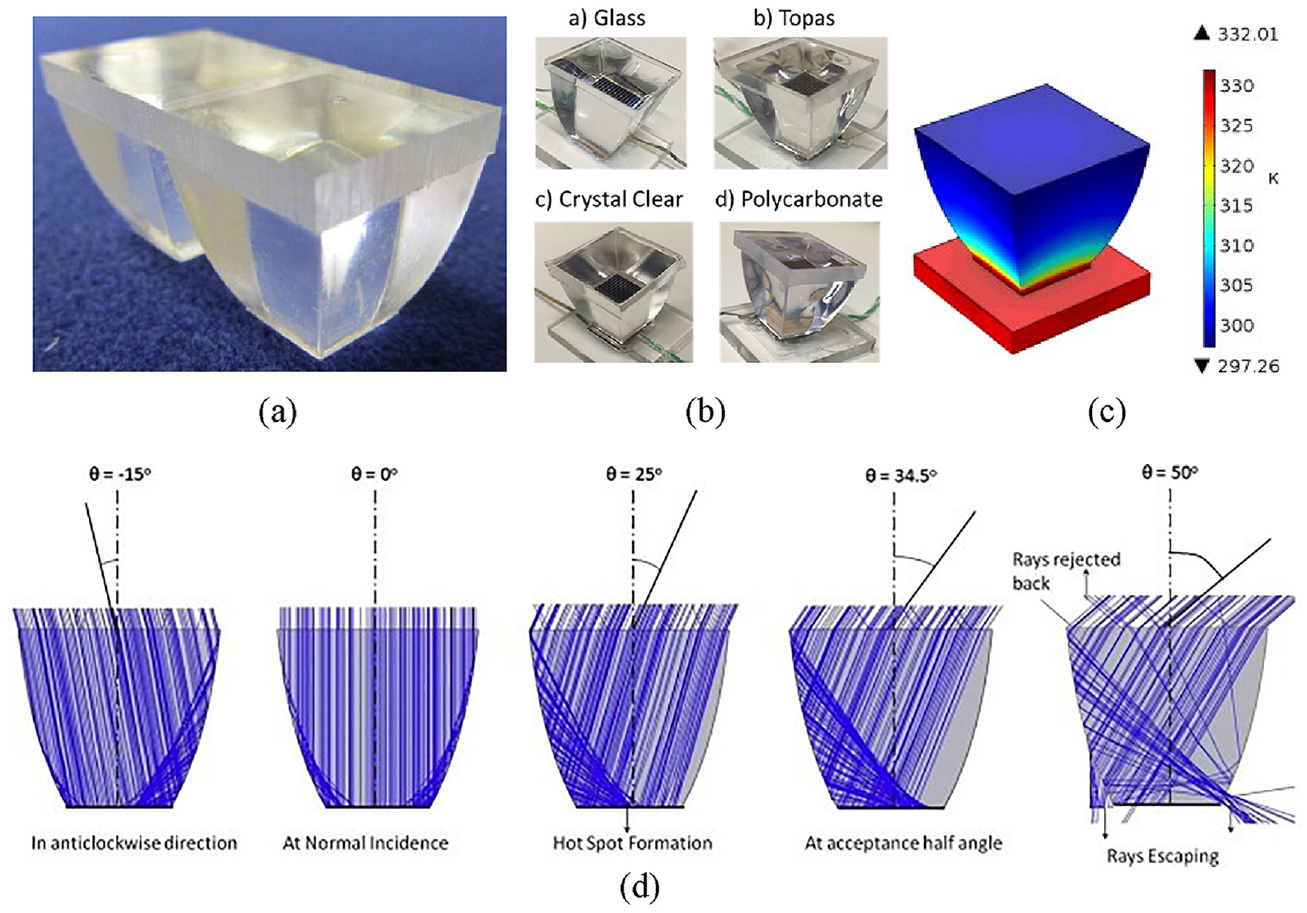
(a) CCPC optic made of polyurethane, (b) CCPC optics made from different materials, (c) temperature distribution across a CCPC (polyurethane) PV unit and (d) ray-tracing diagrams of the CCPC (polyurethane) at different incidence angles.
The above mentioned reflective- and refractive type-CCPC optics are all truncated at around half of the position based on the full-height original CCPC optic. This is because the uppermost part contributes little to the light concentration effect. However, Meng et al. (2016) and Aykapadathu et al. (2018) proposed a novel Absorptive/Reflective CCPC (AR-CCPC) with full-height as shown in Figure 17. It is composed of a thermal absorption part (absorptive rate of 0.94) to collect heat and an optical reflection part (reflectivity of 0.94) to concentrate light. The overall optical efficiency, which takes the optical efficiency generated from the reflective surface and thermal absorbent surface into consideration, can reach up to 94% and maintain a high value at all incident angles.
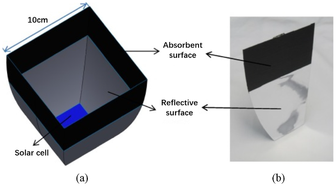
(a) Structure of AR-CCPC and (b) single surface including absorbent and reflective parts.
Building performance prediction of window-glazing systems with complex structures
Following the analysis in preceding sections (Sections 2–5), a wide range of glazing technologies has emerged, aiming to enhance their thermal, optical and electrical properties. A glazing system with good thermal insulation properties, such as a low U-value, can minimise heat loss through windows, thus contributing to maintaining warmth within the room to the greatest extent possible (Li et al., 2023). Higher SHGC values lead to increased cooling load, whereas low SHGC values contribute to greater heating load (Ghosh et al., 2024). In addition to thermal considerations, VT emerges as a significant parameter distinct from SHGC. VT describes how effective the window is in admitting visible light, thereby influencing the illumination of interior spaces (Morrey and Ghosh, 2024). Consequently, these properties of the window-glazing system ultimately impact the overall energy and daylight performance of the building to which they are applied. Therefore, studies need to be conducted to investigate the effects of these innovative window systems on building energy savings and indoor comfort. Among these systems, some feature complex structures, such as windows with integrated solar components and PV cells (Li et al., 2024a, 2024b). When exploring the building performance with such intricate fenestration systems integrated, numerical simulation methods are often employed to examine the detailed dynamic performance. Various building simulation tools, including EnergyPlus, ESP-r, IES, TRNSYS and TAS, have been utilised to investigate the energy and/or daylight performance of buildings equipped with various types of fenestration systems (Crawley et al., 2008; Flor et al., 2018; Liu and Wu, 2022a; Sun et al., 2021a; Sun et al., 2021b; Tan et al., 2020, 2022a; Wang et al., 2017; Wang et al., 2016a). However, one challenge associated with the use of these tools for modelling windows with complex structures is establishing a connection between the precise characterisation of the complex window system and the incorporation of these characteristics into building simulation tools (Sun et al., 2018b). For instance, a significant obstacle is integrating the changing U-value, SHGC and VT of complex window systems into building simulation software like EnergyPlus. Previous building simulation studies often separate the thermal and optical behaviours associated with the fenestration system. This separation is due to the complexity introduced by advanced glazing, which includes complex structures such as glazing with transparent insulation materials (Sun et al., 2016) and optical components (Liu and Wu, 2021, 2022a). The complex structure of these windows presents a challenge for accurate simulation within most building simulation tools (Sun et al., 2018c). Presently, available building energy simulation programmes are not well-equipped to accurately model these complex fenestration systems. Typically, this is because they rely on simplified thermal and optical models to predict heat transfer and light transmittance. For example, simple one-dimensional methods are often used for the prediction of both heat transfer and light transmission through fenestration systems (EnergyPlus, 2024). Glazing systems with complex configurations are often characterised using pre-computed Solar Heat Gain Coefficients (SHGCs) and Visible Transmittances (VTs). Despite being determined using radiosity methods, these values are inadequate for representing the highly complex, angle-dependent interaction implicit when these systems are subjected to realistic time varying patterns of incident radiation (Sun et al., 2017a).
The solar-optical characteristics of this kind of complex fenestration system can be represented by the Bidirectional Scattering Distribution Functions (BSDFs) within EnergyPlus. Sun et al. (2017a) used a Radiance tool genBSDF to generate BSDFs data for a Parallel Slat Transparent Insulation Material (PS-TIM) structure. The generated BSDFs data was then input into a utility, WINDOW, to generate a unified file of the complete system that contains effects of both the PS-TIM and glazing layers. This unified file was finally input into EnergyPlus to couple BSDFs data of the complex fenestration system into the building performance simulation. Using this method, they evaluated the effect of the PS-TIM window on the building energy saving and daylight control. The results showed that when compared to a similar double-glazed window, the application of PS-TIM window could lead to a more comfortable indoor environment and a reduction in energy consumption of up to 35.8%. Sun et al. (2018a) also investigated the building performance when a STPV glazing system (cadmium telluride) was installed with different designs. The BSDF data was used to optically characterise the CdTe window and the Sandia Array Performance Model (SAPM) was used to predict the PV electrical performance. The simulation results showed that when the WWR is smaller than 30%, the adoption of the STPV glazing could not result in the energy saving when compared with a similar double-glazed window. The application of the STPV glazing can result in considerable energy saving at a larger WWR (≥ 45%). The optimal design scenario of applying STPV glazing system can result in a reduction in energy consumption of up to 73%. McNeil et al. (2013) verified the BSDFs data of a specular blind system and micro-perforated mesh generated from the genBSDF through the Tracepro simulation and goniophotometer measurement. Although the BSDF data produced by the Radiance tool genBSDF has been proven to accurately represent the solar-optical characteristics of the complex fenestration system, acquiring BSDF data remains a complex and time-consuming task (Yang et al., 2022). Other researchers also put forward some methods to couple the characteristics of complex window systems into building simulation software. For example, Tian and Su (2018; Tian et al., 2019) developed a modified multiple nonlinear regression model to correlate the transmittance of a tilted dCCPC with sun positions and sky conditions. This model was integrated into building simulation software, EnergyPlus, using Grasshopper software. Using this method, they investigated the energy performance of the dCCPC skylight panel in various locations and climates. The results showed that using dCCPC skylight panel can reduce the cooling energy consumption but increase the heating and artificial lighting energy consumptions. Therefore, it is more suitable for the cities having long hot period and the total energy saving could reach 13%. For the cities with long cold seasons, it resulted in 1%–5% increase of the total annual energy consumption.
Based on the above review of potential methods, the authors proposed a comprehensive model to investigate the thermal, optical and electrical performance of a window system with complex structures and PV cells and also how they shape the daylight and energy performance of the buildings to which they are applied to (Li et al., 2024c). The approach differs from previous studies through the inclusion of a comprehensive model to characterise the thermal, optical and electrical properties of the complex PV window system within the existing building simulation software, EnergyPlus. As an example, the Crossed Compound Parabolic Concentrator Photovoltaic (CCPC-PV) window (Li et al., 2024a, 2024b) was selected as the complex PV window in this study. The Computational Fluid Dynamics (CFD) combined ray-tracing method was used to determine its thermal properties, such as the window temperature and PV temperature of the CCPC-PV window under different weather conditions (i.e. different solar radiation intensity and solar incident angle). While the recursion algorithm combined ray-tracing calculation was used to obtain its solar-optical properties, such as the light transmittance and absorptance of the CCPC-PV window at different solar incident angles. Furthermore, an electrical model was developed by modifying the one built in EnergyPlus (‘Simple’ model) to accurately predict the window power output. This modification involved the temperature coefficient of the PV cell, which varies with PV temperature, and the concentrating ratio of the CCPC-PV window, which determines the solar radiation incident on the PV cells within the window. The thermal, optical and electrical properties obtained from the above models were input into building simulation software, EnergyPlus and the simulation results, such as the light transmittance, solar absorptance, window temperature, window inward convection, radiation and secondary heat flux to the indoor space, SHGC and power output of the CCPC-PV window were compared using a validated 3D CFD combined ray-tracing method under different weather conditions in London (latitude, longitude of 51°32′28″N, 0°7′41″W, respectively) to ensure the obtained properties from individual models are properly coupled into the building performance simulation within EnergyPlus. The flow chart of each stage is shown in Figure 18. The model was then used to obtain relatively accurate building heating, cooling and lighting energy estimates for a typical cellular office room using the CCPC-PV window. The results indicated that the proposed comprehensive model accurately characterises the thermal, optical and electrical properties of the CCPC-PV window within the building simulation software under London climate conditions (Li et al., 2024c). This improvement in accuracy is especially valuable when simulating the energy performance of buildings with a complex PV fenestration system. Furthermore, the CCPC-PV window is more suitable for installation with a larger window-to-wall ratio (e.g. 64%), resulting in a 56.86% energy-saving percentage when compared to a similarly structured double-glazed window under London climate conditions.
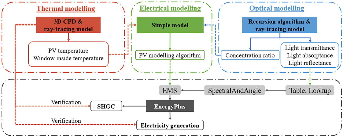
Flowchart of coupling thermal, optical and electrical properties of the CCPC-PV window into window performance simulation within EnergyPlus.
Discussion and future development
Various glazing technologies have developed to reduce the U-value, regulate the SHGC and VT, as well as producing additional power for building windows. Among these glazing technologies, the vacuum glazing-based technologies, such as triple vacuum glazing (Manz et al., 2006) and vacuum glazing with low-e coating (Fang et al., 2007) tend to possess the best thermal insulation property (lowest U-value, e.g. less than 1 W/m2 K). In addition, aerogel is an excellent thermal insulator because it suppresses two of the three modes of heat transfer (conduction and convection). And its U-value can reach 0.60 W/m2 K when it is sandwiched in a double evacuated glazing of 14mm thickness (Michael et al., 2023). The vacuum and aerogel glazing technologies are expected to increase their market share soon, especially for heating dominated climates. The lowest U-value was found as 0.28 W/m2 K for Suspended films. However, it also has the low SHGC (0.17–0.30) and VT (23%–50%; Michael et al., 2023). Thus, it could be used for cooling-dominated climates provided its low VT will improve. The smart window system, such as the passive one (thermochromic window) can adapt to the changing weather conditions to control the visible transmittance and solar heat (with a dynamic VT from 13% to 60% and dynamic SHGC from 0.17 to 0.37; Casini, 2022). The active one (electrochromic window) can change from a clear state (0.47 SHGC and 0.62 VT) to fully tinted state (0.09 SHGC and 0.02 VT; Sbar et al., 2012). It was reported that in cooling-dominated climates, the electrochromic window can decrease the lighting energy consumption by up to 26% and the peak cooling loads by about 20%, compared to systems with blinds (Baetens et al., 2010). The STPV cannot only provide effective thermal insulation, solar shading, but also produce additional power on-site use. In addition, some studies have focussed on the CPV for window application to further increase the PV conversion efficiency while providing better indoor luminance environment and adding additional artistic features to the building façade.
It is evident that advanced window-glazing technologies represent a significant advancement in energy efficiency and sustainability within the building sector, offering benefits such as enhanced thermal performance and improved occupant comfort. Nevertheless, there is a notable absence of comprehensive studies focussing on the accurate integration of these advanced glazing systems into existing building simulation software for performance assessment. The complexity of some of these technologies introduces challenges in characterising their thermal, optical and electrical properties, as well as in their accurate integration into building simulations. Moreover, validating the integration method is crucial. Although tools like Radiance’s genBSDF can incorporate BSDF data into building simulation software like EnergyPlus to represent solar-optical characteristics, obtaining BSDF data remains complex and time-consuming. Thus, simpler and more efficient methods are required to accurately integrate complex window systems into building simulations and validate their performance. These efforts will enhance the estimation of the impact of various complex window systems on building energy consumption and daylight performance.
Conclusion
To assess the effectiveness of window-glazing for building applications, key parameters to consider are the overall heat transfer coefficient (U-value), Solar Heat Gain Coefficient (SHGC) and Visible Transmittance (VT). This paper provides a comprehensive review of various window-glazing technologies, focussing on their U-value, SHGC and visible transmittance (VT). Among these technologies, vacuum and aerogel glazing-based systems exhibit superior thermal insulation properties, with U-values below 1 W/m2 K, making them suitable for heating-dominated climates. Notably, suspended films achieve the lowest U-value at 0.28 W/m2 K, although they exhibit lower SHGC (0.17–0.30) and VT (23%–50%), indicating potential for cooling-dominated climates if VT can be improved. Smart window systems, like electrochromic windows, are also well-suited for cooling-dominated climates due to their low SHGC and VT. Semi-Transparent Photovoltaics (STPV) systems offer not only thermal insulation and solar shading but also on-site power generation. Additionally, research on Concentrating Photovoltaics (CPV) for window applications aims to boost PV conversion efficiency, enhance indoor luminance and incorporate aesthetic features into building facades.
In addition to advancements in glazing technologies to enhance thermal, optical and electrical properties, this paper also reviews methods for accurately integrating these properties into existing building simulation software for performance analysis. While BSDF data generated by tools like Radiance’s genBSDF can be coupled with building simulation software, such as EnergyPlus, to accurately represent solar-optical characteristics, acquiring BSDF data remains complex and time-consuming. The authors propose a comprehensive model to investigate the thermal, optical and electrical performance of window systems with complex structures and PV cells. This approach includes characterising the properties of complex PV window systems within EnergyPlus, offering a simpler and more efficient method for integrating these systems into building simulation software. This exploration enables a thorough investigation into how complex window systems impact building energy efficiency and indoor comfort.
Footnotes
Appendix
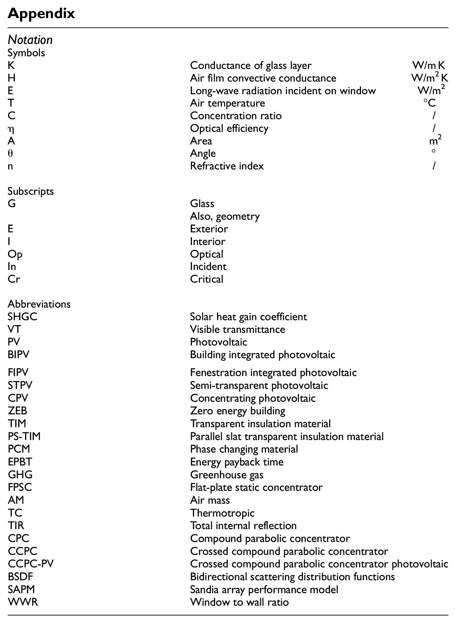
| Notation | ||
| Symbols | ||
| K | Conductance of glass layer | W/m K |
| H | Air film convective conductance | W/m2 K |
| E | Long-wave radiation incident on window | W/m2 |
| T | Air temperature | °C |
| C | Concentration ratio | / |
| η | Optical efficiency | / |
| A | Area | m2 |
| $\rrtheta$ | Angle | ° |
| $\rm n$ | Refractive index | / |
| Subscripts | ||
| G | Glass | |
| Also, geometry | ||
| E | Exterior | |
| I | Interior | |
| Op | Optical | |
| In | Incident | |
| Cr | Critical | |
| Abbreviations | ||
| SHGC | Solar heat gain coefficient | |
| VT | Visible transmittance | |
| PV | Photovoltaic | |
| BIPV | Building integrated photovoltaic | |
| FIPV | Fenestration integrated photovoltaic | |
| STPV | Semi-transparent photovoltaic | |
| CPV | Concentrating photovoltaic | |
| ZEB | Zero energy building | |
| TIM | Transparent insulation material | |
| PS-TIM | Parallel slat transparent insulation material | |
| PCM | Phase changing material | |
| EPBT | Energy payback time | |
| GHG | Greenhouse gas | |
| FPSC | Flat-plate static concentrator | |
| AM | Air mass | |
| TC | Thermotropic | |
| TIR | Total internal reflection | |
| CPC | Compound parabolic concentrator | |
| CCPC | Crossed compound parabolic concentrator | |
| CCPC-PV | Crossed compound parabolic concentrator photovoltaic | |
| BSDF | Bidirectional scattering distribution functions | |
| SAPM | Sandia array performance model | |
| WWR | Window to wall ratio | |
Declaration of conflicting interests
The author(s) declared no potential conflicts of interest with respect to the research, authorship, and/or publication of this article.
Funding
The author(s) disclosed receipt of the following financial support for the research, authorship, and/or publication of this article: This work was supported by the Faculty of Engineering, University of Nottingham and the China Scholarship Council through a joint PhD studentship awarded to Xue Li. This work was also supported by the Engineering and Physical Sciences Research Council, UK (grant number EP/S030786/1).