
Abstract
Super-insulation materials have become more commonplace as highly insulated building envelopes are required to reduce the energy demand of buildings aligned with the net zero targets. While several super insulation materials are available, their environmental impacts and practical on-site limitations hindered their large-scale adoption. The following paper investigates the feasibility of developing hollow-core vacuum insulated panels supported by an internal structural array with different configurations. The designed panel was simulated and measured to evaluate its performance as a thermal insulator for building applications. Panel samples were manufactured from polished stainless-steel plates separated by a PTFE structural array. The change in temperature and heat flux through the sample was measured in a vacuum chamber at a pressure of 0.01 Pa. Thermal conductance was obtained from gradual measurements of heat flux and temperature across the sample after a rapid increase in temperature. Numerical methods that combine molecular and macroscopic solvers were used to model unsteady behaviour recorded in empirical tests. Direct Simulation Monte Carlo (DSMC) was used to calculate the thermal conductivity of the rarefied gas, which was then used to solve the enthalpy equation for the multi-region model. Thermal resistance from empirical tests and numerical methods are in agreement within error bands, the greatest accuracy observed in high conductance models. Thermal resistance as low as 0.17
Introduction
The environmental effects of buildings can be mitigated by improving building efficiency. Over 20% of total energy generated worldwide is employed in buildings (U.S. Energy Information Administration, 2017) and approximately 50% of that energy is used to power space conditioning equipment for buildings in developed countries (Pérez-Lombard et al., 2008). Moreover, buildings’ energy consumption is expected to increase as populations in developing economies shift from rural to urban lifestyle (U.S. Energy Information Administration, 2017). Schemes for sustainable development have been introduced as part of a global cooperation to reduce forces driving climate change. Improved building codes have been introduced to reduce greenhouse gas emissions from buildings. Refurbished and new buildings are now required to meet certain energy demand and carbon emission targets. Parallel to building regulations, third party certification such as Passivhaus, BREEAM and LEED rate and categorize buildings based on their expected performance. Both building regulations and third party certification schemes call for high performance building envelope, as it has a direct effect on energy demand required for space conditioning.
As regulations move towards nearly Zero Energy Buildings and stricter requirements, construction methods have adapted to meet performance goals, see Table 1. Uninsulated bricks walls were replaced by multi-layered insulating constructions (NHBC Foundation, 2015). In the UK, limits for the U-Value of walls have changed from 1.7
Thermal performance standards and Building Regulations around the world.
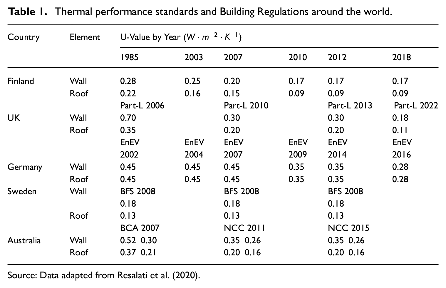
Source: Data adapted from Resalati et al. (2020).
Materials research has produced innovative solutions with improved thermal performance and some insulating technologies have achieved extremely low thermal conductivity and have been named as super-insulators. Aerogels and vacuum insulated panels (VIPs) are examples of super-insulators, with thermal conductivity of 0.014
VIPs offer significant benefits over conventional mainstream insulation materials such as mineral wool and PUR with offering up to six times better performance for the same panel thickness due to their lower thermal conductivity values (Baetens et al., 2010). The high-performance nature of VIPs also allows them to be installed in hard to treat buildings, flat roofs, and balconies where there are space limitations. VIPs are also used as internal insulation in buildings with limitations associated with changing their exterior appearance (Kalnæs and Jelle, 2014).
VIPs, applied to building applications, however, suffer from physical damages caused by on-site handling. Various solutions have been investigated by different researchers to overcome this issue including the research carried out by Gonçalves considering the use of vacuum panels in external insulation finishing systems (Gonçalves et al., 2020). Their work demonstrated that introducing encapsulating solutions to provide flatness and protection to the panels in the handling of the products, defining and assessing a suitable fixation system, and ensuring the connection between construction elements are the primary challenges associated with a practical VIP installation on a construction site. Baetens et al, also confirm these findings by highlighting that VIPs cannot be cut on site and the panels are fragile towards damaging (Baetens et al., 2010).
VIPs have also been investigated in the literature to facilitate a selective exchange of heat when desirable. A switchable thermal conductivity would allow for a better insulative property in the colder months of the year or a higher conductivity allowing for the excess heat to scape in the warmer months of the year. Erlbeck et al., studied the performance of switchable VIPs using different core materials including silica powder, silica agglomerates, and silica gel (Erlbeck et al., 2020). The investigation included the time of aeration and evacuation and the corresponding change of heat conductivity along with the change of gas-pressure. The study demonstrated that silica gel in combination with helium as filling gas offered the best results. The time of aeration was also highlighted in Sonnick’s study as a primary requirement for switchable VIPs (Sonnick et al., 2022). Dehwah investigated the performance of switchable insulation systems using a two step thermal conductivity control mechanism and demonstrated that it can significantly reduce energy consumption for heating and cooling systems in the US (Dehwah and Krarti, 2020). Cui and Overend highlight that the available literature on switchable insulation is unstructured and fragmented given the early stage of development in the technology(Cui and Overend, 2019). It is however worth mentioning that most studies that considered a switchable characteristic for VIPs relied on conventional VIPs with a core material.
The conventional VIPs suffer from high environmental impacts relative to the other insulation materials. The majority of the environmental impact associated with VIPs is attributable to the fumed silica core material. The production process of fumed silica is very energy intensive requiring high temperature treatments of the raw materials. It has been demonstrated that over 90% of the overall environmental impact for fumed silica-based VIPs is associated with their core material (Karami et al., 2015; Resalati et al., 2021). Other lower impact core materials such as glass fibre are also used as a core material for VIPs but their higher sensitivity to air and moisture penetration through the laminated aluminium envelope reduces their service life significantly (Resalati et al., 2021). Moreover, the multi-layered envelope cannot be separated into its constituent materials in a streamline process, leading to landfill or incineration at their end of life (Bayus et al., 2016). Although attempts to overcome VIP’s limitations are an active area of research, such as the use of getters to adsorb permeating gases and mitigate pressure increase (Yamamoto and Ogura, 2022), wide adoption by the building industry remains elusive.
By comparison, hollow-core VIPs’ envelope, manufactured from stainless steel, could largely be recycled, or reused contributing to greater resource efficiency, circular economy, and cradle-to-cradle material life cycle. While the specific method to fasten these panels to the façade lies beyond the scope of this research, it has been reported that 96% of steel used in construction in the UK is recycled or reused (Sansom and Avery, 2014). Hollow-core VIPs could be manufactured from repurposed demolition material and later refurbished or recycled, avoiding landfill or incineration.
The following study, therefore, informed by the challenges associated with conventional VIPs studied in the literature, presents a comprehensive feasibility study of developing a hollow-core VIP to overcome the highlighted limitations of Vacuum Insulation panels. The hollow core concept primarily aims to reduce the environmental impact of VIPs associated with the use of core materials, and improve the fragility of VIPs through a novel structural design. This study also highlights the limitations and opportunities of developing hollow core VIPs laying the foundation for future research and development activities. Limitations presented by testing equipment, fabrication and evacuation process have limited the scope of this research to small sample sizes tested only in controlled laboratory conditions and without consideration to on-site handling and mechanical integration with the façade. The feasibility and thermal conductance analysis conducted invites further research relevant to building cladding systems such as safety concerns, fire response, mechanical fastening, and wind loading.
Very limited research has been conducted on the technology at the time of writing and only the publication by Nemanic could be found in peer reviewed sources, primarily describing fabrication with little mention of thermal properties(Nemanic, 1995). Performance of hollow-core VIPs rely on some of the same principles as common VIPs but the low conductivity core material is replaced by a structural array and a rigid envelope, Figure 1. This configuration can help overcome fragility limitations and could potentially work as a dynamic element with an insulating state and a conducting state, helping reduce heating or cooling demands by adapting to ambient conditions. Studies on the feasibility of hollow-core VIPs could not be found in literature. This research, therefore, in the following sections, investigates the feasibility of developing hollow-core VIPs considering the materials selection, structural configuration, and their thermal performance including the details of the contribution of heat transfer mechanisms to the total heat transfer through the panel.
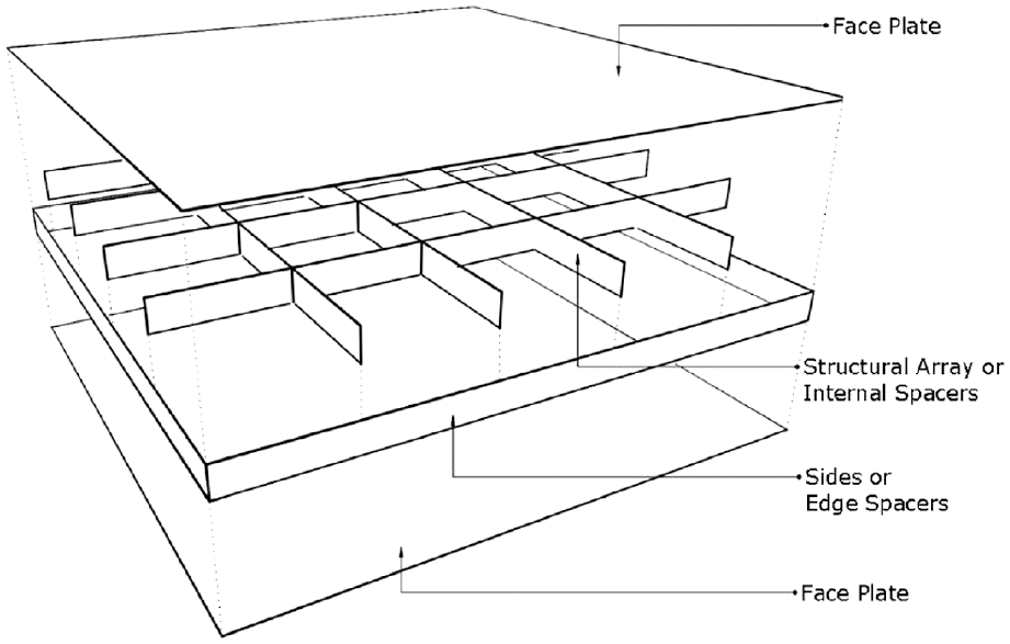
Hollow-core VIP diagram.
Materials and methods
Thermal resistance of hollow-core VIPs was calculated by finite difference numerical models and compared to empirical measurements. Numerical models use Direct Simulation Monte Carlo (DSMC) to simulate molecular heat transfer through the rarefied gas. Macroscopic properties of the gas were calculated from DSMC results and incorporated as a fluid region with fixed pressure and velocity into a multi-region model to simulate heat transfer across the complete model.
Simulations model transient behaviour observed in the empirical tests, during which, the rate of change of temperature and heat flux was measured to calculate the thermal resistance of samples.
Numerical model of heat transfer
Predicting heat transfer through a vacuum cannot be established accurately by solving Navier-Stokes equations as the conservation equations fail when the molecular mean free path [λmfp] is of the same scale as transport terms. However, by simulating molecular interactions, the macroscopic flow properties can be determined (Bird, 1994). By this relationship and Fourier’s law, the thermal conductivity of a rarefied gas can be calculated from heat flux predicted in molecular simulation. Consequently, the Direct Simulation Monte Carlo method (DSMC) can be linked to OpenFoam’s chtMultiRegionSimpleFoam and chtMultiRegionFoam solvers allowing heat transfer simulation of multi-region objects which include a rarefied gas region.
OpenFoams’s solvers have been widely verified in academic publications. The SIMPLE and PIMPLE algorithms are accurate to within 5% and 3% of experimental data and within 6% of FLUENT, a proprietary software (Robertson et al., 2015).
Many validation and verification studies have been conducted to assess OpenFoam’s accuracy and capacity in CFD (Churchfield, 2010; Jasak and Beaudoin, 2011; Muntean et al., 2009), molecular dynamics (Dongari et al., 2011; Scanlon et al., 2010; White et al., 2018), heat transfer (Bansal et al., 2012; Mangani et al., 2007; Starikovičius et al., 2016), and other phenomena.
Model
Simulation models were configured to match the properties and conditions of empirically tested samples, resulting in subtle differences in temperature boundaries of each case. Variation in boundary conditions prohibit direct comparison of heat flux and its rate of change between cases. Consequently, predicted thermal resistance was chosen as an adequate metric for the final comparative analysis.
The model is comprised of two 300 by 300 mm aluminium plates separated by a sample measuring either 25 mm or 50 mm in thickness, depending on the case, Figure 2. The 300 mm by 300 mm size is dictated by the internal dimensions of the vacuum chamber as well as the minimum distance required from the edges of the panels to avoid its associated thermal impact on the centre of the panel measurements.
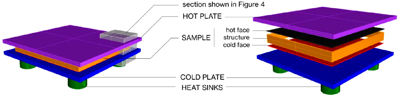
Diagram showing regions in the simulation model. Modelled after experimental configuration. The model colours shown are chosen exclusively to accentuate and differentiate between different model regions.
The cold (bottom) plate sits on four heat sinks and is surrounded by rarefied gas regions simulating conditions inside the vacuum chamber. The sample is comprised of two parallel steel plates adjacent to the heat distribution aluminium plates, a structural array separating the steel plates, and the vacuum region(s) contained within. Adjacent to the cold (bottom) plate is the cold face of the sample, its material properties are set to match the tested sample made from mirror polished stainless steel. On the opposite side of the sample is the hot face, also mirror polished stainless steel and adjacent to the hot (top) aluminium plate. These sample faces (hot and cold) are separated by the structural array, made from PTFE. Detailed material information and thermophysical properties can be found in Table 3.
The fluid region for DSMC simulations was initialized as a uniform temperature field with the average value between boundary conditions, which were configured to match temperatures measured in experiments.
The same boundary values were included in the multi-region simulation model whose fluid region’s macroscopic properties were calculated from DSMC simulations. The model is initialized from a steady state with an overall uniform temperature as measured in empirical tests after evacuation of the chamber and before the resistance heater was activated. The model has two fixed temperature boundaries, one hot and one cold, simulating the interface with the heater and with the vacuum chamber. The cold temperature boundary at the base of the heat sinks is approximated as a fixed temperature since observed temperature fluctuations were negligible. Immediately after model initialization the uppermost mesh faces of the hot plate are set to a fixed boundary condition mimicking the measured stable temperature from the activated resistance heater.
Mesh & regions
The rarefied gas region used for DSMC simulations measures 250 mm length by 250 mm width with a maximum height (sample thickness) of 50 mm. The largest cell dimension (12 mm) is within recommended mesh properties as it is much smaller than the approximate mean free path λmfp of air calculated by the hard sphere model at a 30°C average temperature (Bird, 1994). The resulting DSMC mesh consists of 4000 hexahedra cells with a maximum aspect ratio of 2.5.
Multi region models solved by chtMultiRegionFoam consist of131,072 cells with a maximum aspect ratio of 17.78. Mesh details for each region can be found in Table 2.
Region cell count.
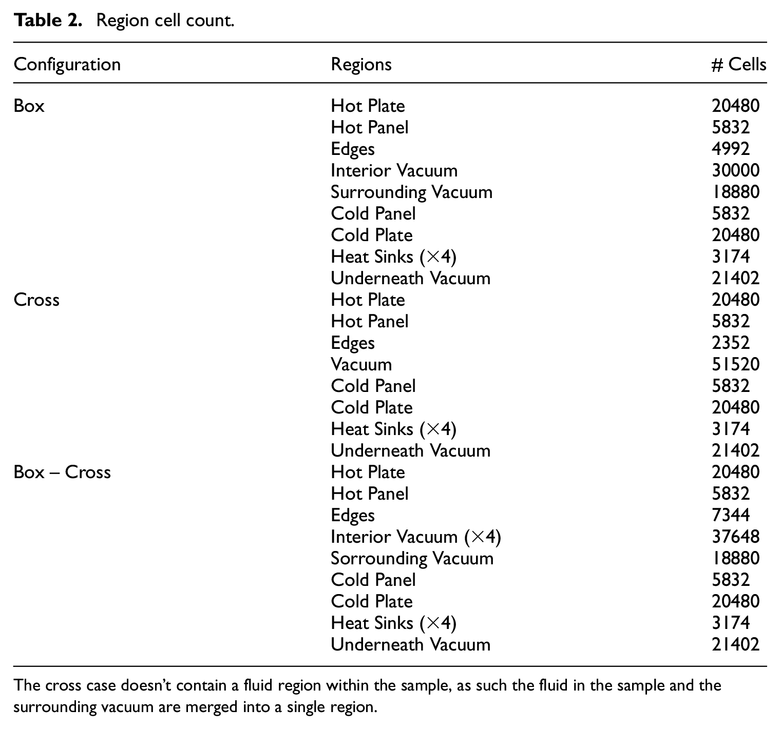
The cross case doesn’t contain a fluid region within the sample, as such the fluid in the sample and the surrounding vacuum are merged into a single region.
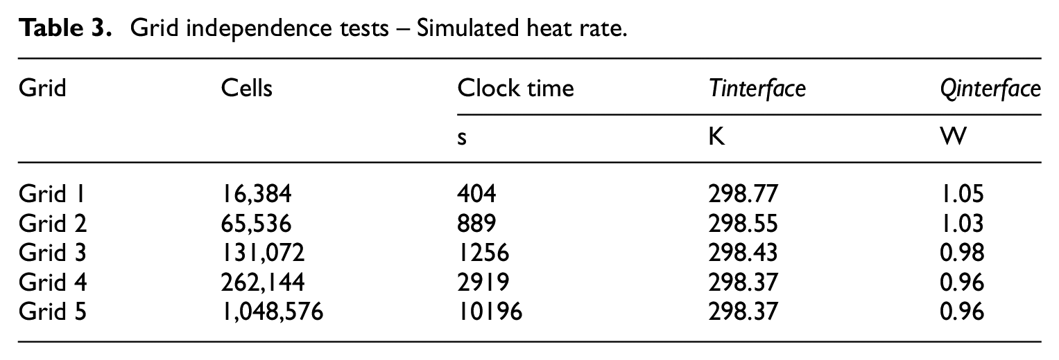
Grid independence tests simulated five grids, the finest mesh consisted of over 1 million cells while the coarse mesh consisted of16,000 cells, Figure 3 and Table 3. The chosen mesh (grid 3) showed less than 1% difference in temperature and 2% in heat flux by comparison to finer meshes, Figure 4. Grid 3 was chosen due to balanced accuracy and computation time, Figure 5, which is compounded by the large number of required simulations.
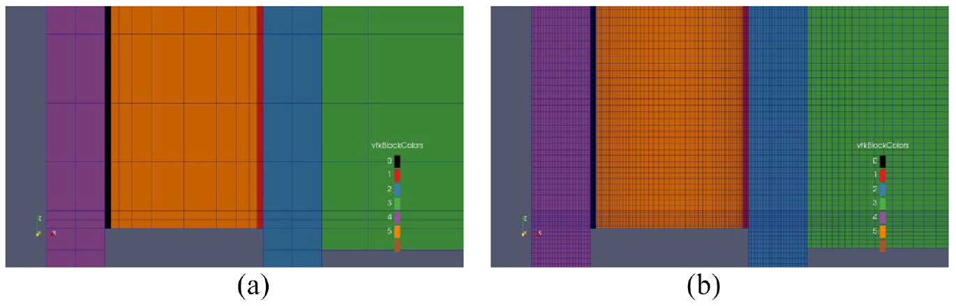
(a) Coarse mesh with 16,384 cells and (b) Fine mesh with 1,048,576 cells. Mesh refinement was focussed on sample elements with greater consideration along the main direction of heat flow.
Grid independence tests – Simulated heat rate.
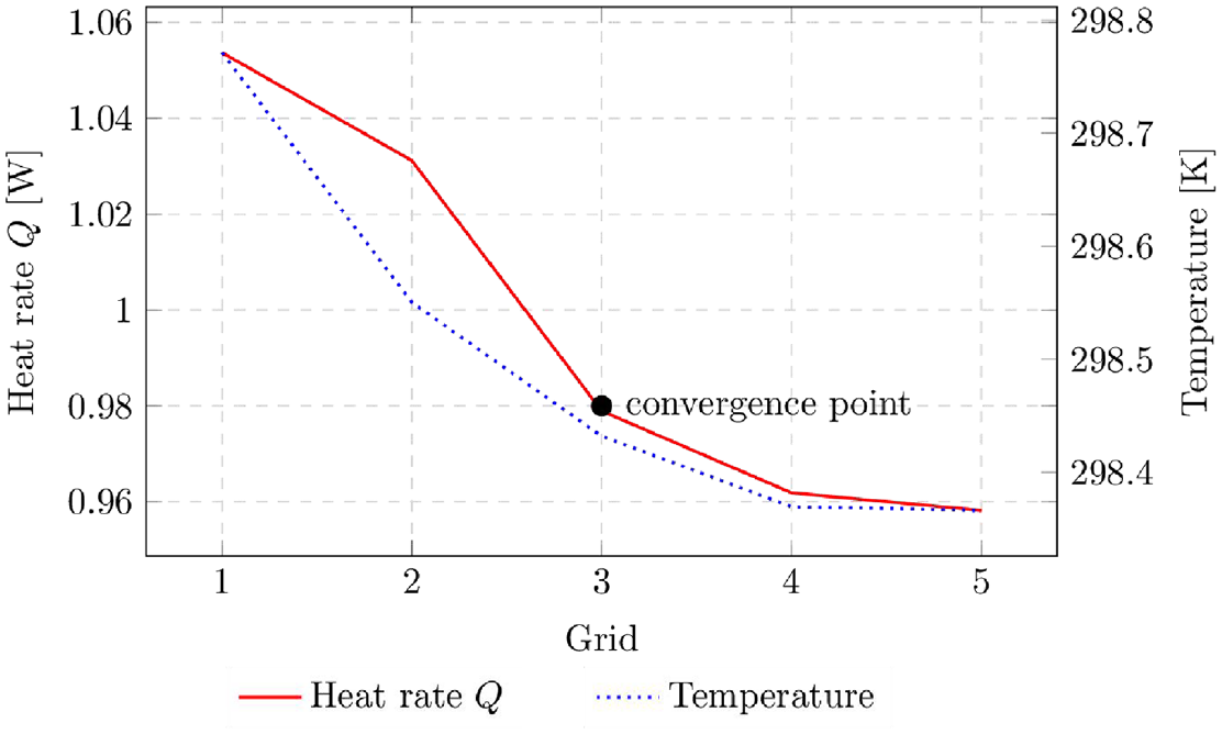
Grid independence analysis. Simulated temperature T and heat rate W at the interface between the temperature distribution aluminium plate and the sample’s steel panel.
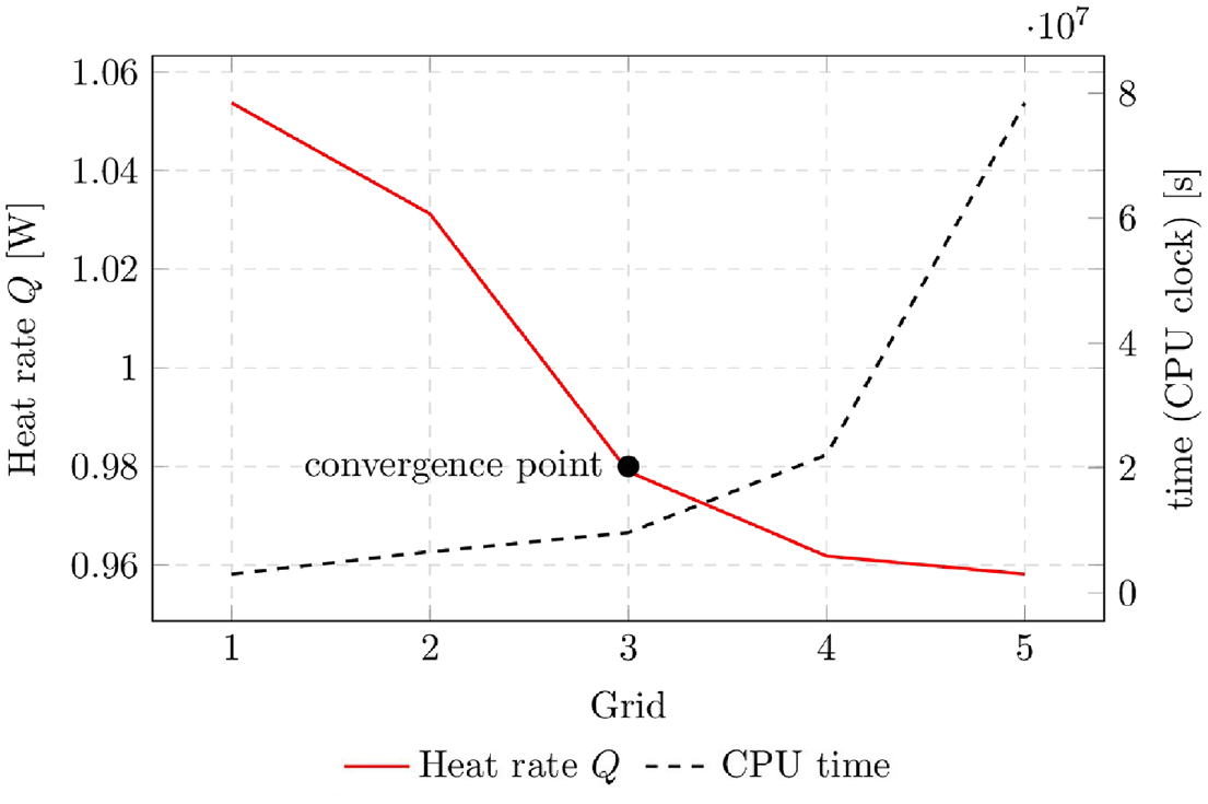
Grid independence analysis. Heat rate W at the interface between the temperature distribution aluminium plate and the sample’s steel panel, and execution time (in CPU clock time) t.
Boundary conditions
The model has two types of boundary conditions, adiabatic and uniform fixed temperature. Fixed temperature boundaries are used to set cold and hot temperatures at model limits and these values are defined by averaged empiric measurements from experiments conducted in the vacuum chamber. The hot boundary is set by the Kapton heater’s average stable temperature and is applied to the uppermost faces of the Hot-Plate region. The cold boundary is applied to the base of the Heat Sinks and corresponds to the average measured temperature in the sample after achieving steady state, following chamber evacuation and prior to heater activation. Remaining mesh limits are adiabatic.
Material properties
Physical properties by material assignment are displayed in Table 4.
Physical properties from model used in simulations. DMSC simulations were used to determine properties of the rarefied gas.
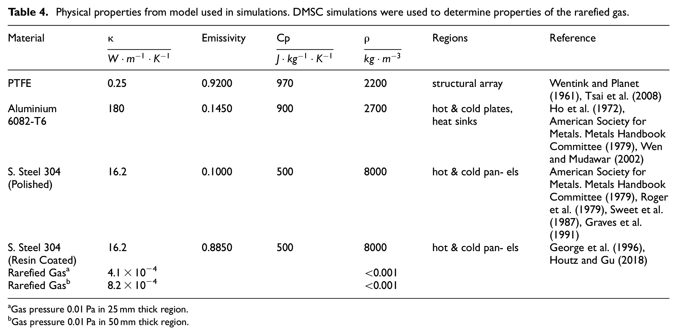
Gas pressure 0.01 Pa in 25 mm thick region.
Gas pressure 0.01 Pa in 50 mm thick region.
Thermal contact conductance
The microscopic imperfections found at the interface between materials introduces a thermal resistance that affects thermal contact conductance. This effect is very noticeable in the tests and simulations conducted given the lack of an interstitial gas, low emissivity of materials, and a low-pressure load. In the presence of low-pressure loads, the interstitial gas will be the main heat transfer medium at the contact interface (Boeschoten and Van Der Held, 1957). In our research the interstitial gas is rarefied and has a low thermal conductivity. All factors considered lower the thermal contact conductance by several orders of magnitude by comparison to ambient conditions.
Correlations researched by Thomas and Probert were used to calculate aluminium to aluminium contact. Equation (1) expresses the correlation that was plotted against data recorded in literature, producing a correlation coefficient greater than 0.9 (Thomas and Probert, 1972). The mass of the measuring rig and torque from screws were added to calculate the load. Consequently, the calculated nominal contact conductance at the base of the rig is estimated at 11

Where hc is the thermal contact conductance
Heat flux was measured in an empty rig with and without high vacuum grease to estimate its effect at the contact interface, and the measured flux was compared to analytical solutions. The observed behaviour of the rig with a thermal interface agent (Dow Corning high vacuum grease) suggest that thermal contact conductance is 100–150
Experimental measurement of thermal conductivity
Thermal conductivity was measured in several samples with different configurations and two variations of internal surface emissivity, 0.9 and 0.12. The variations of the tested samples were used to evaluate heat flux at different sections of a full size hollow-core VIP. Samples were manufactured to fit the testing equipment and were placed inside a vacuum chamber to simulate the internal vacuum condition of an evacuated panel.
Test conditions were limited to a maximum temperature of 43°C and a maximum Δ T of 25°C., which are common temperature limits found in the built environment.
Testing equipment
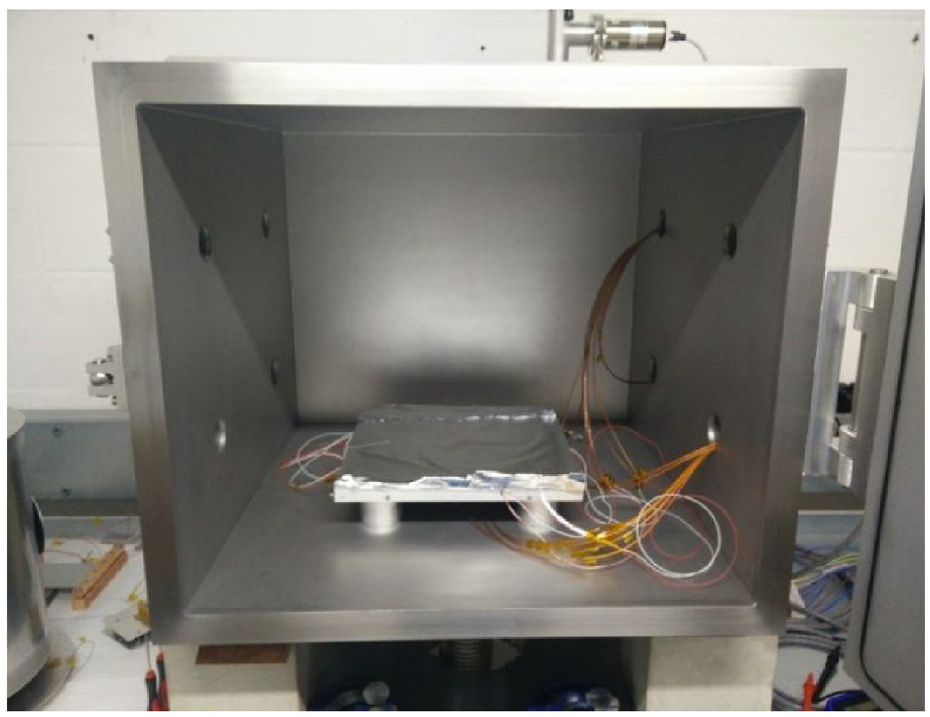
Heat flux and temperature were measured at two points of the sample’s boundaries parallel to heat flow, centre and corner of the sample. The sample and measuring instrumentation were held by a test rig and placed inside a vacuum chamber (600 mm width × 600 mm length × 500 mm depth), Figure 6. Figure 7 shows the bottom plate of the test rig being set-up, having only one of two employed heat flux sensors and its corresponding temperature sensors. Additional sensors are included prior to setting the sample and the top plate with mirrored instruments, finally, the top plate of the rig is covered with aluminium foil to mitigate radiative exchange between the heating pad and the chamber.
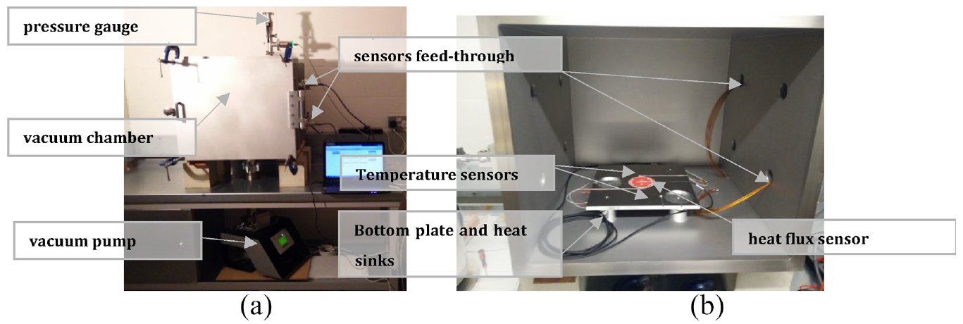
(a) Initial configuration for the vacuum chamber and (b) Starting to fit instruments into the test rig. The vacuum chamber sits on top of bench and the vacuum pump is located beneath the chamber.
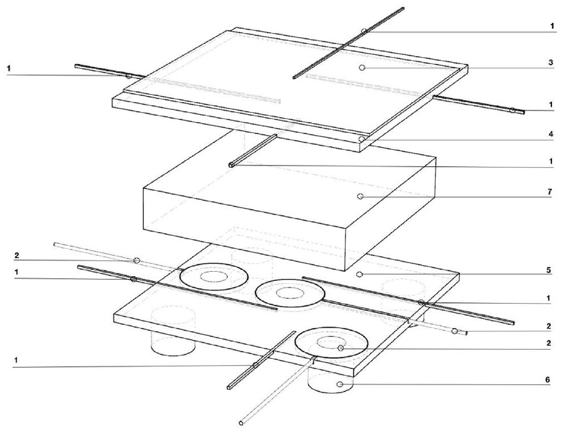
Test Rig: (1) Temperature sensors (PT-100). (2) Heat flux sensors (Hukseflux HFP01). (3) Insulated Kapton Heater (Omega Engineering KH-1012-P, 10 by 12 in, 2.5
Pump system
The Turbolab 80 Turbo Molecular pump system is used to evacuate the chamber. The pump system includes a TurboVac SL 80 H along with a DIVAC 0.8 T backing Pump, max speed of 1200 Hz (Oerlikon Leybold Vacuum, 2009, 2015). A Leybold PENNINGVAC PTR-90N pressure gauge is used due its wide measuring range (1 × 10⁵ Pa to 1 × 10⁻⁶ Pa) (Oerlikon Leybold Vacuum, 2016).
Temperature sensors
Five RS-Pro PT-100, class A, platinum resistance sensors are placed within the test rig. The first sensor is used as part of the thermal control system, and it’s placed over the resistance heater. Two more temperature sensors per side are placed next to the heat-flux sensors, Figure 8. The sensors have a temperature range from −50°C to +500°C, a response time of 0.1 s, and a tolerance of ±0.25°C at 50°C (RS Pro, 2017).
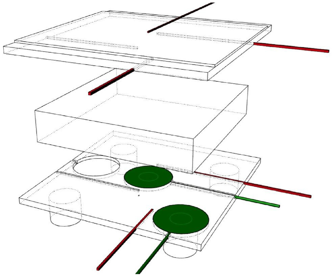
Diagram showing placement of temperature and heat flux sensors. The temperature sensors are adjacent to heat flux sensors which terminate in a ceramic disc. Readings are taken at the centre and edge of the sample.
Heat flux sensors
Hukseflux HFP01 sensors come with factory calibration and with a nominal sensitivity of 60
Resistance heater
A KH-1012-P Kapton Insulated Resistance Heater by Omega Engineering was attached to the upper plate. This heater has a power density of 2.5
Data gathering
A factory calibrated Keithley 2700 data logger on 5 second interval delay was used to gather all measured data.
Samples
The sample is composed of a PTFE structural array capped by parallel stainless-steel plates (Grade 304). The PTFE structural array was tested in three different configurations (Figure 9). All contact interfaces included a thin layer of Down Corning high vacuum grease to fill interstitial voids. Heat flux was measured the corner and centre of the samples on both sides parallel to heat flux. Sample deformation during tested was not a concern because the sample was tested in a vacuum chamber, was not hermetically sealed, and was evacuated at the same rate as the chamber, consequently, there was no pressure difference between the sample and surrounding environment and no stress loading.
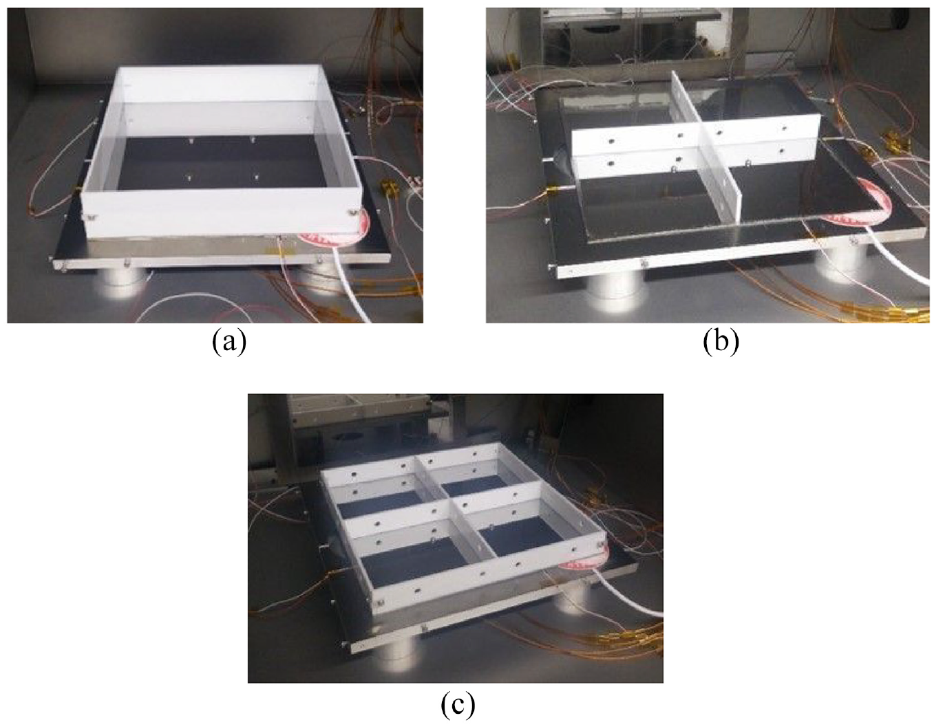
Tested samples’ configuration. The polished stainless steel face plates are bolted onto the temperature distribution aluminium plates and the PTFE structural array is held between the stainless-steel plates. The images show three configurations of the structural array: (a) box configuration, (b) cross configuration and (c) box-cross configuration. These variations represent different positions within a full-size sample. Samples were not deformed in the evacuation process because sample and chamber are evacuated simultaneously avoiding pressure differential and any pressure driven stress loads.
Plates
The plates are finished as a polished mirror surface or as a resin coated surface to evaluate the magnitude of radiative heat transfer by comparison to other transfer mechanisms. Moreover, application of different surface finishes with different thermal emissivity provides insight into the effect of altering internal emissivity as could be achieved with thermochromic or electrochromic coatings. All plates measure 250 mm × 250 mm and 1 mm thick. The mirror polished stainless steel plate is a low emissivity surface. To achieve a high emissivity surface, an unpolished plate was coated with East Coast Fibreglass Supplies’ 2:1 fast acting epoxy resin with 10% total volume super black epoxy colour pigment. While the epoxy coating was measured to be less than 1 mm, tapering near the edges was noticeable. Epoxy coatings were cured at 20°C for 48 h and then baked at 100°C during 6 h to reduce outgassing
A FLIR thermal imaging camera was initially used to determine surface emissivity of the coated sample. Under controlled temperature conditions the emissivity value on the FLIR camera was adjusted until the temperature reading from the camera matched temperature readings from a K-type thermocouple attached to the plate. These readings agree with literature (George et al., 1996; Houtz and Gu, 2018). Figure 10 shows that a piece of 3 M Scotch Super 88 vinyl electrical tape covering the temperature sensor at the centre of the sample vanishes completely in infrared imaging, indicating that the plate coating and the tape have a similar thermal emissivity. The 3 M electrical tape is known to have a thermal emissivity of 0.95 ± 0.05 (Madding, 1999). Surface emissivity of both samples was measured by Becker Ltd. conforming to ASTM C1371-15 standard test method in addition to thermal imaging and literature review. The resin coated sample was found to have an emissivity of 0.9 validating the approximation with the thermal imaging method. The mirror polished sample’s emissivity is 0.12.
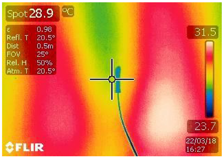
Infrared image of the resin coated sample maintained at a constant ±30°C temperature. The measurement point is aiming at black electrical tape covering a K-type thermocouple. The resistance heater used for this test is a silicone covered pad unfit for use in vacuum environments, this resistance heater shows that the uneven silicone cover produces heat concentration spots.
Structural array
The panel’s plates were simply supported by an array of PTFE strips laser cut from a 3 mm thick sheet. The structural support elements were manufactured to be assembled as a ‘Box’ measuring 250 by 250 mm, supporting the panel’s plates by its edges, or as ‘Cross’ measuring 244 by 244 mm, supporting the plates from its centre. In addition, they could be used simultaneously in a ‘Box-Cross’ configuration. Strips were cut with two different widths, 25 and 50 mm.
PTFE was selected as a suitable material because it has sufficiently low outgassing to support a high vacuum. Moreover, it can be laser cut to produce precise parts. Nylon and acetal were discarded in favour of PTFE due to a larger mass loss in low pressure environments, making it more difficult to achieve a high-vacuum environment; PTFE has a total mass loss (TML) of 0.23% and a collected volatile condensable materials (CVCM) of 0%, nylon (TML of 2.02% and CVCM 0%) and acetal (TML of 0.37% and CVCM 0.02%) (NASA- National Aeronautics and Space Administration, 2018).
Testing procedure
The method for measuring the thermal resistance of the sample depends on the thermal conductance of the sample and the rate of increase in temperature. The gradual increase in temperature and heat flux on the cold side of the sample were measured after a rapid increment in temperature on the hot side; a similar method was described by Collins and shown to produce accurate results (Collins and Simko, 1998).
The sample was maintained in steady-state in an evacuated chamber at an internal pressure of 0.01 Pa before rapidly increasing the temperature of the top plate to 40°C. The resistance heater was set to a default 25°C. The rate of increase in temperature and heat flux measured on the cold side of the sample are affected by the sample’s thermal properties such as thermal conductance and thermal mass. The activity of the resistance heater was logged to determine the amount of energy introduced into the system. The resistance heater was activated continuously during the heat-up process to raise the temperature to 40°C, the sample was maintained at this temperature during several hours.
The heat flux readings will equal the temperature difference between opposite sides of the sample divided by the sample’s total thermal resistance. The method was calibrated with common materials whose properties were known. The first measurements were conducted with the test rig without any sample but with a thin layer of high-vacuum grease acting as a thermal interface, Figure 11. These results suggest a thermal conductance of the vacuum grease layer between 100 and 150
Calibration of the test rig. A thin layer of high-vacuum grease is used as thermal interface between the aluminium plates and heat flux through the rig is measured. Aluminium foil covers the Kapton resistance heater to reduce radiative exchange with the chamber.
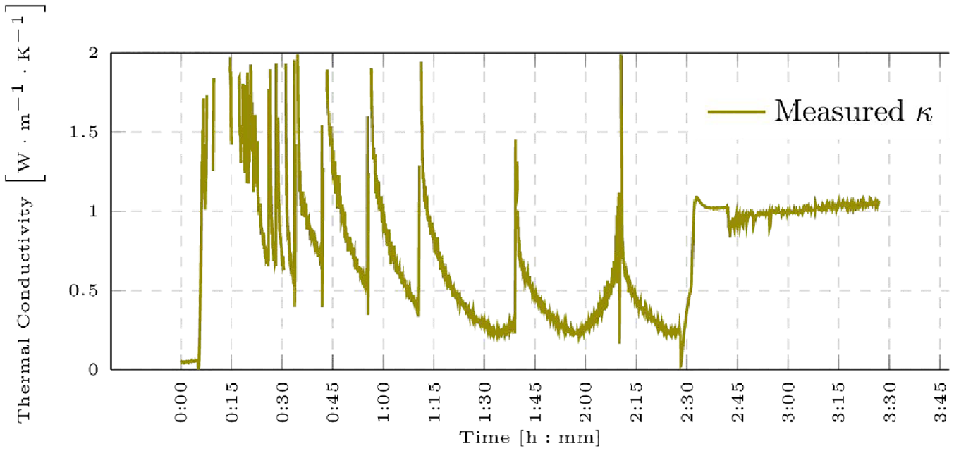
Measurement of thermal conductivity for a 3 mm thick soda lime glass. The plotted values are obtained from the ratio between heat flux and temperature difference (ΔT). The plot stabilizes at the 2:30 mark when the temperature is increased to 40°C. Previous values are erratic due to ΔT values that tend to 0 resulting in an undefined expression of thermal conductivity.
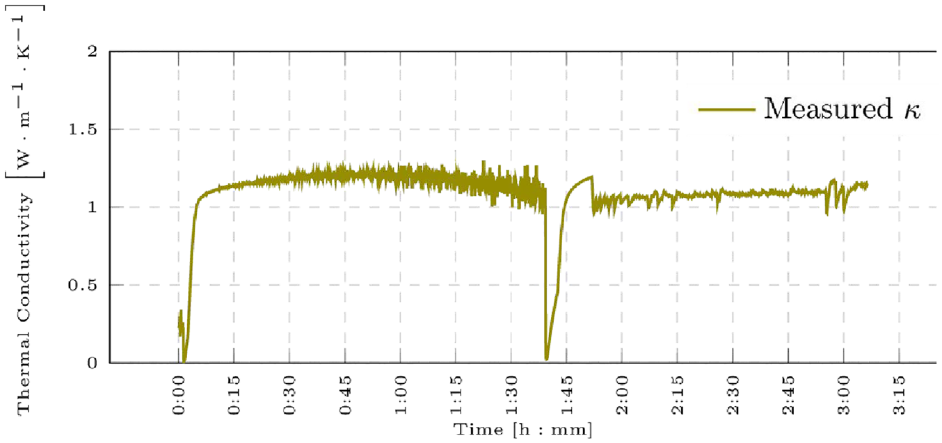
Measurement of thermal conductivity for a 8 mm thick soda lime glass. The plotted values are obtained from the ratio between heat flux and temperature difference (ΔT). The plot stabilizes before the 2:00 mark when the temperature is increased to 40°C. Undefined and erratic thermal conductivity values during initial stages were avoided by slowly raising the sample’s temperature by 5°C prior to the rapid change in temperature.
Theory/calculation
Finite element analysis
The vacuum region is first analysed independently to calculate the rarefied gas’ thermal conductivity using kinetic theory. Simulations were run with a Direct Simulation Monte Carlo solver called dsmcFoam, part of OpenFoam’s toolkit. Values obtained for the heat transfer rate through a rarefied gas agree with Smoluchowski’s temperature discontinuity model for parallel plates (Lafferty, 1998).
The gas’ effective thermal conductivity calculated from molecular simulations is used to define the properties of the vacuum region used in chtMultiRegionFoam, OpenFoam’s solver for multiple regions. As the vacuum region will remain at a constant pressure and will transfer heat only through molecular interactions, only the energy equation needs to be solved and not the moment equations. Consequently, a ‘frozen flow’ is specified, fixing pressure and velocity in the system, and solving only for the internal energy component in enthalpy.
DSMC foam
The Direct Simulation Monte Carlo method, DSMC, approaches molecular interaction from a numerical probabilistic model rather than a deterministic model, reducing computation time and resources. This is achieved by solving the Boltzmann equation, equation (2) (Bird, 1994).

The DSMC method uncouples intermolecular collisions from molecular motion over a time step smaller than the average rate of collision and is only suitable for dilute gas flow (Bird, 1994). At each time-step, first, molecules are displaced by the correct distance and then a representative set of intermolecular collisions is calculated. If the time-step is smaller than the rate of intermolecular collision results will be independent of time-steps. Figure 14 diagrams the dsmcFoam algorithm.
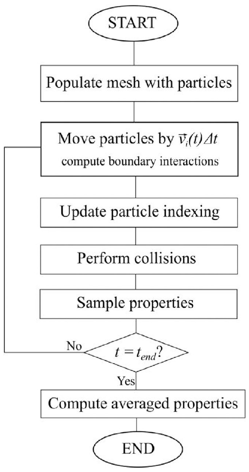
dsmcFoam flowchart. Adapted from (White et al., 2018).
ChtMultiRegion
The transient solver, chtMultiRegionFoam, uses the Laplacian equation and PIMPLE solver. PIMPLE solves for a compressible fluid with an implicit time discretization scheme. Viscous dissipation and flow dilatation are neglected due to the condition of the sample which experiences negligible pressure changes (Ferziger and Peric, 2002). Consequently, the fluid is treated as incompressible by fixing pressure and velocity.
The sum of kinetic energy (K) and internal energy (e) equal the fluid’s total energy. Since the sample is not generating energy or doing any work mechanical and source terms are not used, the resulting enthalpy equation solved in the simulation is as follows.

The terms from the equation deal with energy transferred by flow, heat diffusion, and radiation, respectively. The View Factor method is used to calculate radiative heat transfer.
Uncertainty analysis
The overall uncertainty of the model was calculated by the root sum of the squares method. Uncertainty of variables in the model can be found in Table 5. Thermal conductivity uncertainty was taken from ECSS guidelines as ±10% (Klein, 2000). Surface emissivity uncertainty was defined by the range covered in values found literature for Aluminium, resin surfaces and polished steel (American Society for Metals. Metals Handbook Committee, 1979; George et al., 1996; Graves et al., 1991; Ho et al., 1972; Houtz and Gu, 2018; Roger et al., 1979; Sweet et al., 1987; Wen and Mudawar, 2002), which is higher than ±0.03 recommended in ECSS standards (ECSS Secretariat ESA-ESTEC, 2011). Uncertainty in thermal contact conductance, or thermal bridge, is derived from the model discussed in Section 2.1.1.
Uncertainty of variables present in simulations.
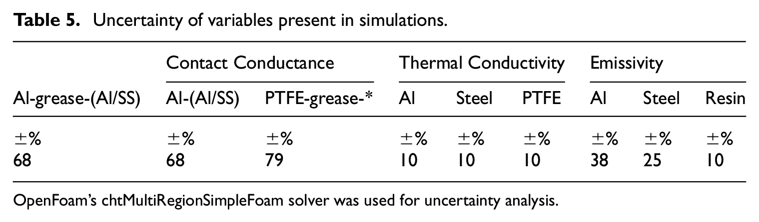
OpenFoam’s chtMultiRegionSimpleFoam solver was used for uncertainty analysis.
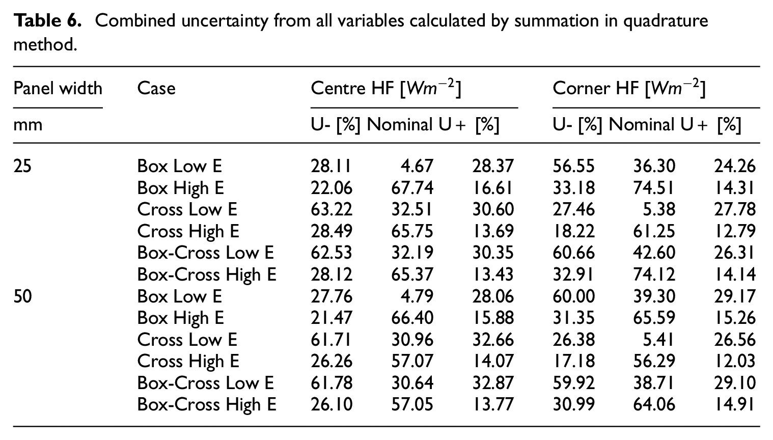
Table 6 shows combined uncertainty for all cases and Table 7 shows the results for individual variable uncertainty in 25 mm Box configurations. A large deviation from nominal values is expected where the main heat transfer mechanism has high uncertainty, for example, Sensors without direct solid contact will be greatly affected by variation in surface emissivity. It is interesting to note that variation of contact conductance has an asymmetric effect on heat flux. A lower contact conductance coefficient compounds insulation on the sample, but the effect of a higher contact conductance coefficient is not as noticeable due to the low thermal conductance of the sample. The heat bridge effect is compounded by high conductance samples, conversely, it’s mitigated by low conductance samples.
Combined uncertainty from all variables calculated by summation in quadrature method.
Uncertainty per variable on 25 mm thick ‘Box’ configuration.
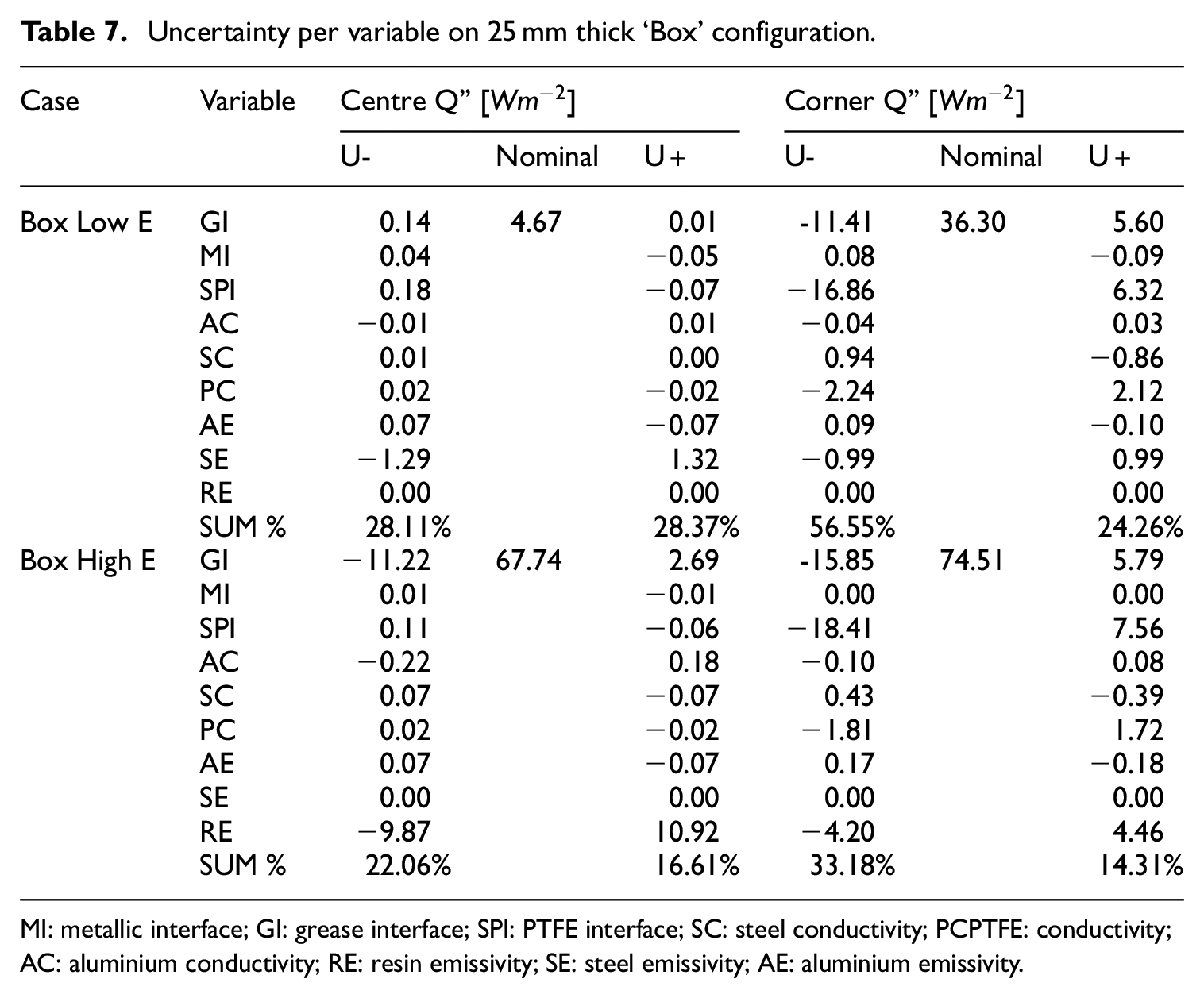
MI: metallic interface; GI: grease interface; SPI: PTFE interface; SC: steel conductivity; PCPTFE: conductivity; AC: aluminium conductivity; RE: resin emissivity; SE: steel emissivity; AE: aluminium emissivity.
Results
Measured and simulated thermal resistance in areas subject to solid conduction, such as the central area in Cross configurations and the corner area in Box configurations agree with analytic models, increasing panel thickness increases thermal resistance. The proportional change in thermal resistance with increasing panel thickness between these two configurations differs due contact area (10% difference between cases) and view factor which in turns affects radiative exchange.
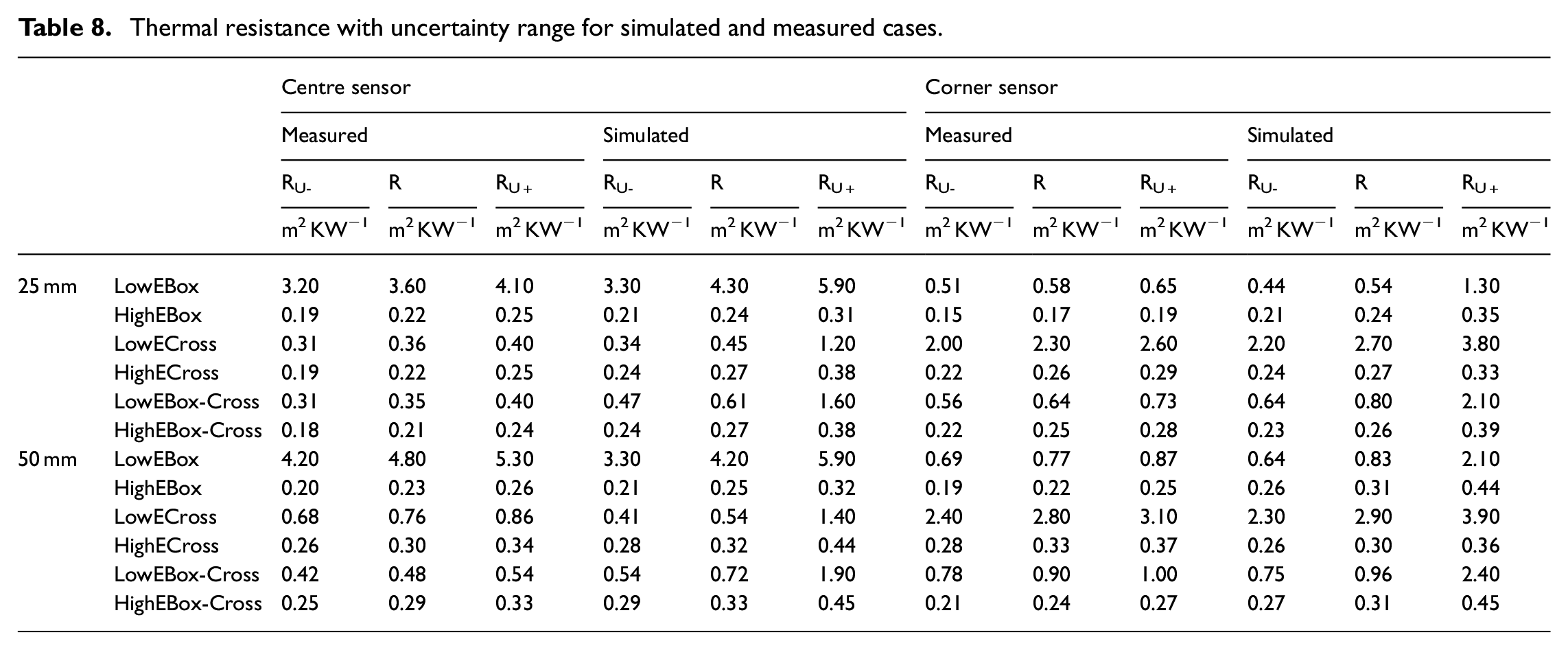
Thermal resistance values sampled at areas with direct solid conduction agree within 8% for all configurations in high-emissivity models, Table 8, but a 30% variation was observed in low-emissivity cases. This variation is thought to be caused partially by the view factor in Box-Cross configurations and consequently its inherent radiative transfer, and by increased lateral flux along additional PTFE structural elements. A comparison of regions with direct solid conduction between the Box-Cross models and the other models (centre sensor for Cross models, corner sensor for Box models) shows that the thermal resistance at the corner for Box-Cross models is consistently larger than its Box counterpart for all tested configurations. The difference between thermal resistance measured at the centre is similar between Cross and Box-Cross models with 25 mm thickness but diverges in the thicker 50 mm samples with low emissivity. This behaviour is attributed to a compound effect of increased lateral heat flux along the structural array and increased participation from radiative transfer due to a larger view factor coefficient.
Thermal resistance with uncertainty range for simulated and measured cases.
The primary transfer mechanism in low emissivity models is solid conduction as can be seen in Figure 15(a) with the majority of heat flux registering at the position of solid elements. Solid conduction transfers more than 40% of total energy transferred in low emissivity cases. High emissivity models indicate that radiation takes a dominant role and heat flux becomes nearly uniform over the entire panel area, Figure 15(b).
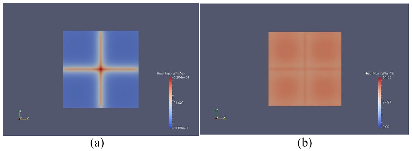
25 mm thick Cross configurations, heat flux at 3600 s: (a) low emissivity and (b) high emissivity. Results from OpenFoam chtMultiRegionFoam simulations.
The largest heat flux magnitude was recorded roughly 30 min after the rapid temperature increase, by this time energy storage of the system becomes saturated and ΔT is largest.
Measured and simulated results
Table 8 summarizes thermal resistance values for empiric tests and numerical models. The modelling method produced accurate results for all cases, agreeing within error bands with empirical measurements, nonetheless, it is important to continue narrowing uncertainties and improving modelling accuracy. The best and most consistent results came with dominant radiant energy transfer, where all cases agree within 5%. Cases with dominant solid conduction show agreement between 5% and 20%. The low emissivity models with dominant radiative transfer, such as the central sensor for the low-E Box model, showed the largest offset between nominal measured and simulated thermal resistance (up to 50%), although within error margins determined by overall system uncertainty. Low emissivity cases are most sensitive to model inaccuracy, discrepancies such as a shift from surface emissivity from 0.09 to 0.1, can produce a significant percentage shift in predicted thermal resistance. This sensitivity is reflected in its overall uncertainty.
After the systems’ energy storage is saturated, the thermal resistance progression is very similar between empirical measurements and simulated models. This can be seen in Figure 16 for the 25 mm thick Box sample with low emissivity plates. The difference in the peak and steepness of the curve is due to the temperature overshoot in empirical tests where the Aluminium plate reaches 43°C before settling at around 40.8°C. The PID thermal controller was calibrated in vacuum but would still underestimate the efficiency of the Kapton resistance heater producing a two-degree overshoot.
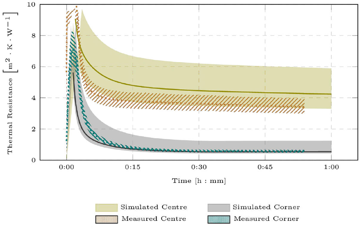
25 mm thick Box configuration with low emissivity. Thermal resistance plotted against time for empirical tests and simulated model. Instants after the temperature is increased the thermal mass of the sample is absorbing energy resulting in exceedingly large calculated thermal resistance. Once the thermal mass has become saturated the calculated thermal resistance becomes constant and measured and simulated values overlap within error bands.
Figures 17 to 19 plot the position of simulated and measured thermal resistance with regards to each other.
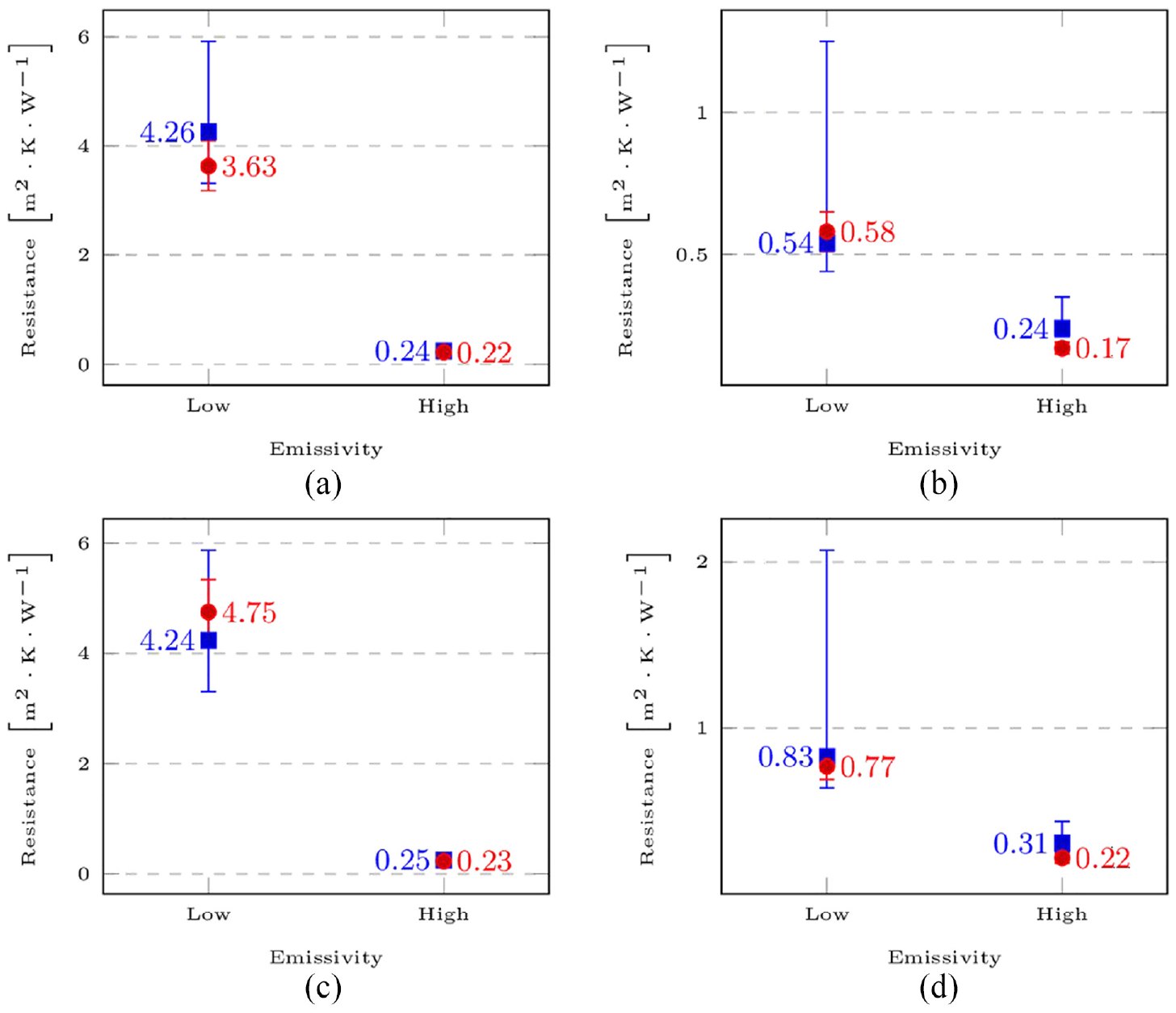
Results comparison for BOX configurations. Measured thermal resistance is plotted with a red circle and simulated thermal resistance is plotted with a blue square. Agreement is found between numerical models and empirical tests; however, low emissivity cases show the greatest discrepancies.
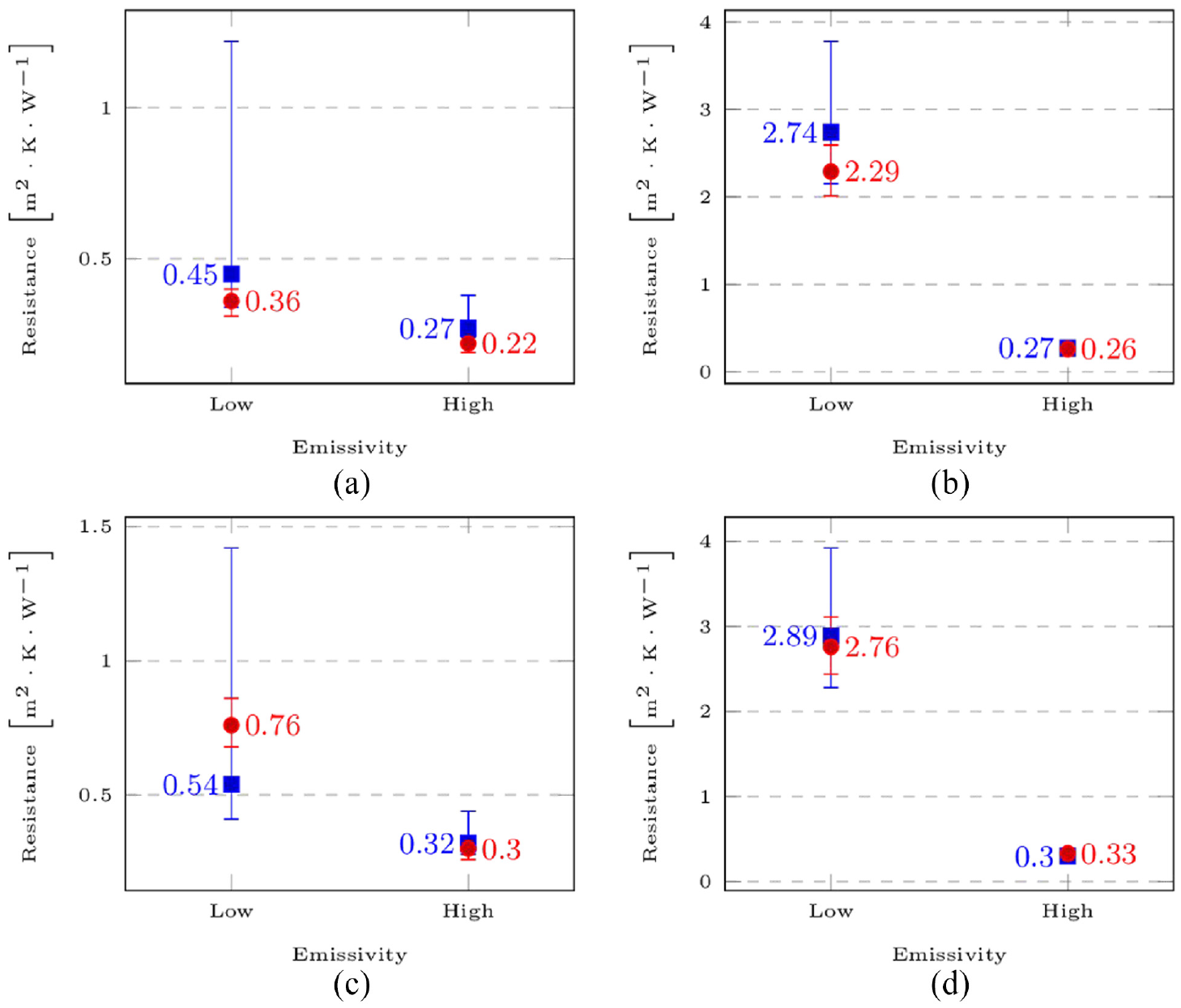
Results comparison for CROSS configurations. Measured thermal resistance is plotted with a red circle and simulated thermal resistance a blue square. Agreement is found between numerical models and empirical tests. Low emissivity environments where radiative transfer is dominant (corner sensor) is most sensitive to deviations, the predicted thermal resistance greatly exceed measured values.
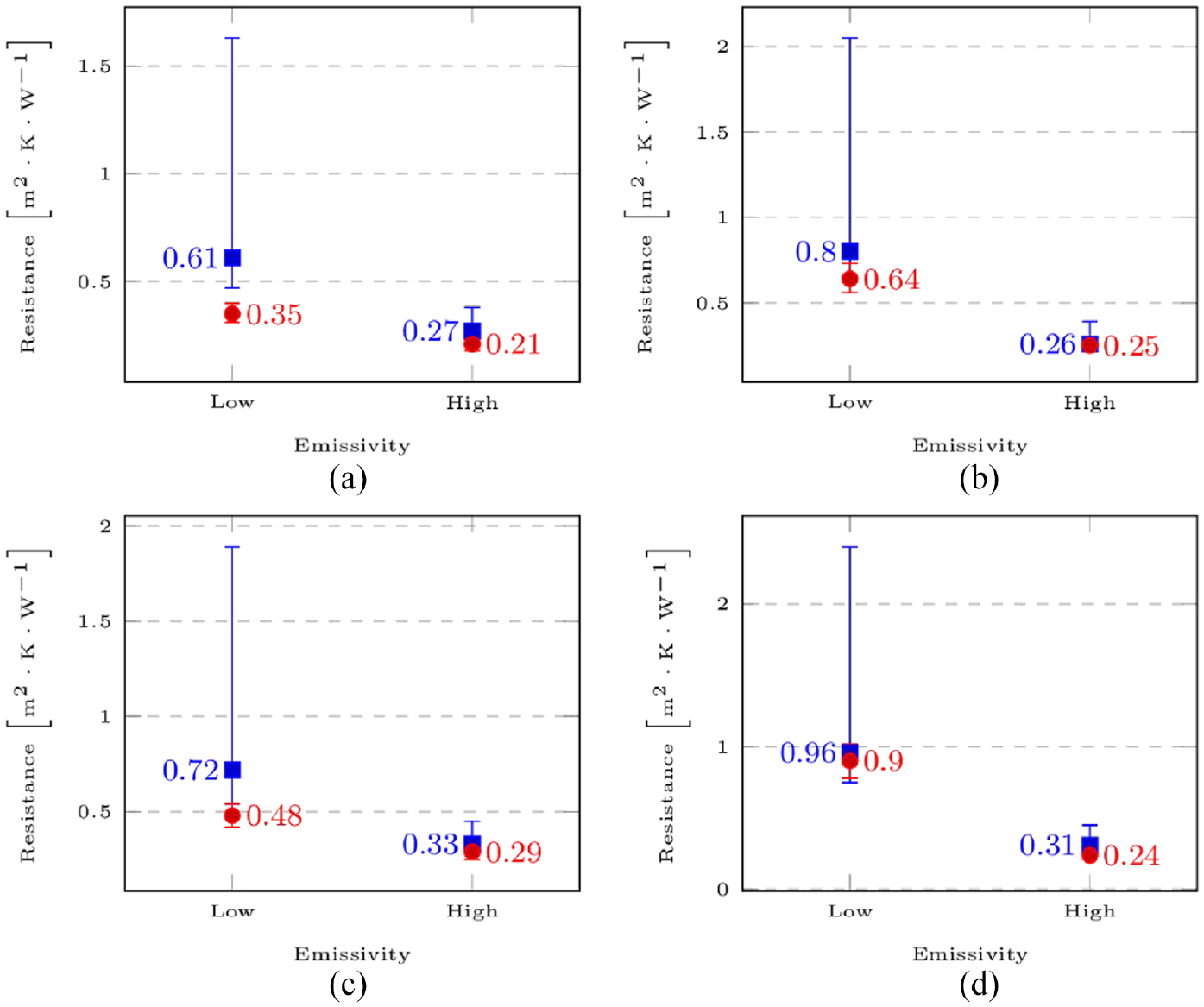
Results comparison for BOX-CROSS configurations. Measured thermal resistance is plotted with a red circle and simulated thermal resistance is plotted with a blue square. Close agreement is found between numerical models and empirical tests when radiation and conduction are the primary heat transport mechanisms.
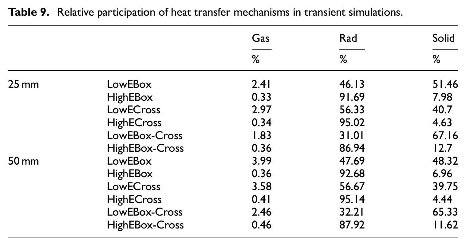
Participation of individual heat transfer mechanisms
Table 9 summarizes the relative participation of heat transfer mechanisms. Gas conduction is always responsible for less than 1% of energy transferred except in low emissivity cases, increasing to 3%. With a constant pressure of 0.01 Pa, as the panel becomes thicker the rarefied gas approaches a transitional flow and gas conduction increases accordingly. Radiative transfer increases by roughly 1% with the thicker 50 mm samples. Solid conduction is diminished with larger cross-sections.
Relative participation of heat transfer mechanisms in transient simulations.
Discussion
Results from the tested samples and simulated models suggest that a hollow core VIP can be an efficient insulator. This is supported by the 4.75
Observed thermal conductivity at the centre of sample in the low emissivity BOX configuration is 0.01
While results from areas devoid of solid elements in low emissivity scenarios indicate highly insulating properties, solid conduction is the dominant heat transfer mechanism. Further, the effects of increasing surface emissivity are noticeable even from small increases from 0.1 to 0.125. A high surface emissivity dominates heat transfer suggesting that hollow-core VIPs will be better suited not as a super insulator but as a versatile facade element for places with seasonal or daily climate variation, purging or intaking heat to diminish space conditioning demands and prevent overheating.
Obtained results show a thermal resistance range from
The modelling technique and results can be used to balance competing requirements, such as the panel’s structural integrity and thermal conductance. Consequently, this facilitates design development of a large building-scale element while reducing prototyping costs.
Limitations of the PTFE structural array
PTFE has good insulating properties and is compatible with high vacuum environments, however its mechanical properties are much weaker than common building materials such as aluminium, steel, and timber. PTFE has an elasticity modulus of 0.4 GPa and a yield strength of 9 MPa, and it should be noted that yield occurs at high deformations (Schramm et al., 1973). By comparison, AISI304 stainless steel has an elasticity modulus between 180 and 200 GPa and a yield strength of 215 MPa; aluminium 6082T6 has an elasticity modulus of 70 GPa and a yield strength 250 MPa (Courtney, 2005).
In addition to withstanding mechanical stress imposed by the panels own weight plus ambient pressure, PTFE will deform at the point of contact and conform to the surface of contact, thus improving the thermal interface and its inherent thermal contact conductance, Figure 20.
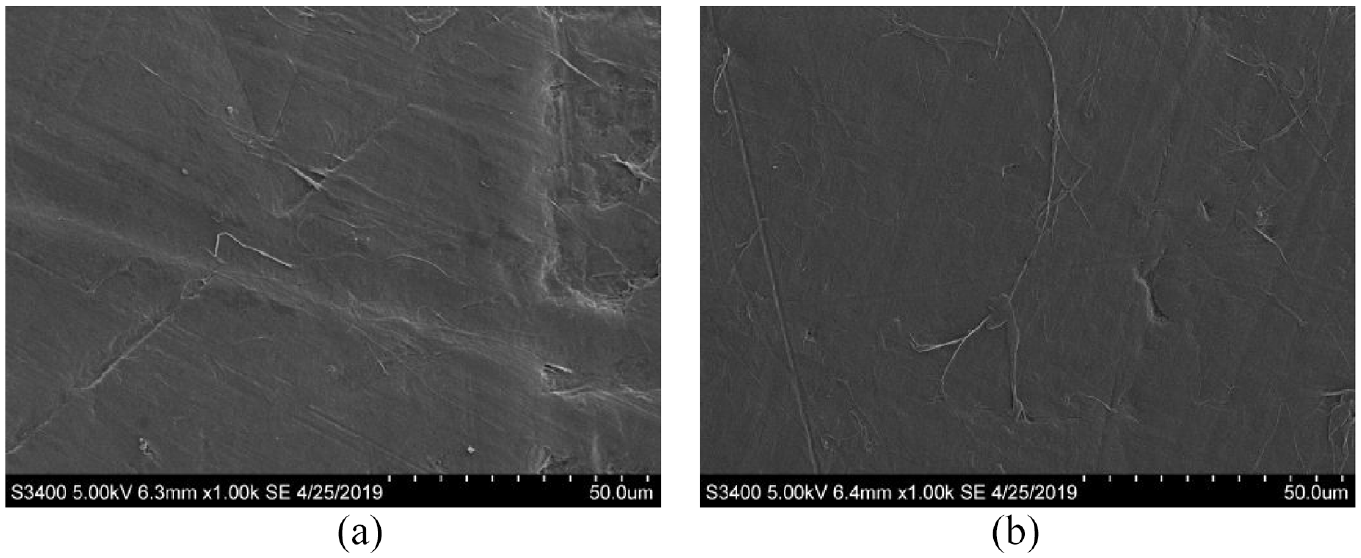
SEM imaging of PTFE sheet used for sample fabrication: (a) uncompressed PTFE sample and (b) compressed PTFE sample with 750 N in a hydraulic press; samples were gold played (10 nm layer). The compressive load per unit area is equal to the resulting load from pressure differential between the evacuated interior of the panel and ambient pressure. Microscopic surface irregularities of the uncompressed sample are not present in the compressed sample as the material has undergone plastic deformation.
Its weak mechanical properties dictate that under the same mechanical stresses, a structural array composed of PTFE elements will need greater reinforcement than with steel or aluminium elements. This inevitably leads to an analysis of competing requirements, thermal conductance, and mechanical integrity to assess the feasibility of a hollow-core VIP with an internal PTFE structure.
Potential of a stainless-steel structural array
Stainless steel is commonly employed in high vacuum and ultra-high vacuum applications due its low out-gassing properties. Moreover, this material can be baked to high temperatures to remove surface impurities and adsorbed moisture (Lafferty, 1998). Contrary to PTFE, stainless steel has excellent mechanical properties but a much higher thermal conductivity (16
Limiting thermal contact conductance of a steel array is theoretically possible by restricting contact to a small area. This approach has been previously attempted by an array of staggered glass tubes (Nemanic, 1995) and calculations of contact area between a non-conforming flat surface and a curved steel element with a radius of 0.5 mm (Johnson, 1987) suggest this solution can provide improved insulating performance over thicker PTFE elements.
Conclusions
A finite element model was developed to simulate the performance of hollow-core VIPs and was validated against empirical measurements. The simulation method involved DSMC molecular simulation to calculate the effective thermal conductivity of the rarefied gas, which was then used in a multi-region transient simulation to solve the enthalpy equation and calculate the thermal conductance of the models, which were modelled to match the manufactured samples. The thermal resistance of the samples was calculated from measured temperature and heat flux values on the cold side of the sample after a rapid temperature increase on the hot side.
The samples consisted of two parallel stainless-steel plates separated by a PTFE structural array in three different configurations (Box, Cross and combined), and two thicknesses (25 mm and 50 mm). Since neither thermochromic nor electrochromic coatings were available during this research, the samples’ plates were coated with epoxy resin or finely polished, providing two different emissivity values to investigate the change of thermal conductance by affecting radiative transfer in the infrared range.
Empirical measurements conducted for all sample permutations resulted in thermal resistance as high as 4.75
Thermal contact conductance was found to have a significant effect on the overall thermal resistance of the panel. Results obtained from empirical tests and simulated models indicate that good insulating properties can be achieved with a high-vacuum environment (0.01 Pa) and low surface emissivity as that of polished stainless-steel plates. However, solid conduction from the structural array remains the greatest obstacle even when fabricated with low conductivity materials such as PTFE.
This paper provides the most comprehensive feasibility study of hollow-core VIPs highlighting the opportunities and limitations of further developing the technology. Such analyses lay the foundation for further optimization of the design. The analysis also provides insight into the contribution of different heat transfer mechanisms in such configurations, identifying areas for improvement.
Future research
This research focussed on investigating the feasibility of hollow-core vacuum insulated panels by establishing a method for modelling its thermal behaviour and validating it against measurements conducted for different structural array configurations.
Future improvements to this research involve determining the overall effective thermal conductance of a full-size panel, which include all thermal bridges introduced by the internal structure as well as the envelope containing the vacuum. In addition, determining service life and understanding the hollow-core VIP’s performance over time would greatly enrich this area of research.
Footnotes
Declaration of conflicting interests
The author(s) declared no potential conflicts of interest with respect to the research, authorship, and/or publication of this article.
Funding
The author(s) disclosed receipt of the following financial support for the research, authorship, and/or publication of this article: This work was supported by Oxford Brookes University 150th Anniversary Research Studentship [grant number 1118137512], and by Consejo Nacional de Ciencia y Tecnologia (CONACyT) Mexico [grant number 428262].