
Abstract
Reducing energy consumption and Greenhouse Gas (GHG) emissions is an essential part of the clean growth and climate change framework recently developed by the Canadian government, which emphasizes the importance of energy-efficient building constructions. In this paper, the effects of thermal mass and placement of the thermally massive layer within wall assemblies on the transient thermal performance of walls and energy performance of a case study office building were studied. Three climate conditions representative of the heating-dominated, temperate, and cooling-dominated climates were considered. As for the assessment of energy demands, two cases for the indoor air temperature were taken into account: (i) indoor temperature was maintained at 20°C throughout the year, and (ii) during summertime, there was a set-point of 24°C and a setback of 35°C during the rest of the day while during wintertime, the set-point and setback values were 22°C and 18°C, respectively. The cases were compared according to the resulting decrement factor, the time required to reach quasi-steady state conditions, amplitudes of changes of heat fluxes and indoor surface temperatures, and the energy demands. The results showed that, for the cases studied, the wall, for which the thermally massive layer is not directly exposed to the indoor and outdoor climate conditions, resulted in the lowest decrement factor, the minimum amplitude of changes of heat fluxes and indoor surface temperatures, and maximum time required to reach quasi steady-state conditions. As for the energy performance, on the other hand, the wall, for which the thermally massive layer is exposed to the interior and exterior climate conditions, performed best amongst the cases investigated.
Introduction
A recent clean growth and climate change framework developed by the Canadian government (Environment and Climate Change Canada, 2016) has set the goal of reducing the GHG emissions by 45% until 2030 compared to the amount emitted in 2005. Heating, cooling, and lighting in Canadian buildings are responsible for approximately 30% of the total energy use and 17% of GHG emissions (Theodosiou and Papadopoulos, 2008). In addition, according to the results of a survey published by National Resources of Canada (NRCan) (National Resources Canada’s Office of Energy Efficiency, 2014), nearly 20% of total buildings’ energy consumption in Canada is devoted to offices. Due to these considerations, as well as the increasing costs of energy resources in Canada, finding feasible measures for reducing the buildings’ energy use and GHG emissions is necessary in Canada, in particular for office buildings. One of the factors that can contribute to the overall thermal performance of a building is the thermal mass effect. Using materials with high heat storage capacities as part of building envelope systems leads to the potential of reducing energy consumption and improving thermal comfort of the occupants (Congedo et al., 2020; Deng et al., 2019; Hu et al., 2020; Zilberberg et al., 2021).
According to the International Energy Agency (IEA) (Yoshino et al., 2017), climate conditions, Heating, Ventilation, and Air Conditioning (HVAC) systems, building envelope, interior design, operation and maintenance, and occupancy behavior are the six parameters affecting the energy consumption of the buildings. In addition, based on the literature, assessing the thermal performance of building envelope systems has been divided into two stages, namely thermal performance of the envelope components themselves without investigating their contribution to the overall energy performance of the buildings; and the impact of envelope design parameters on the overall energy use of the buildings.
Amongst the essential design parameters of building envelopes containing thermally massive walls, the possibility of improving the energy performance and thermal comfort of the buildings as a result of the choice of wall layers’ configuration (i.e. sequencing of layers) has been a topic of interest for many papers. A number of relevant literature regarding the impact of placement of thermally massive layers and insulation layers of exterior walls are summarized and presented in Table 1.
Literature review summary regarding the effects of the placement of insulation layers and thermally massive layers of exterior walls.
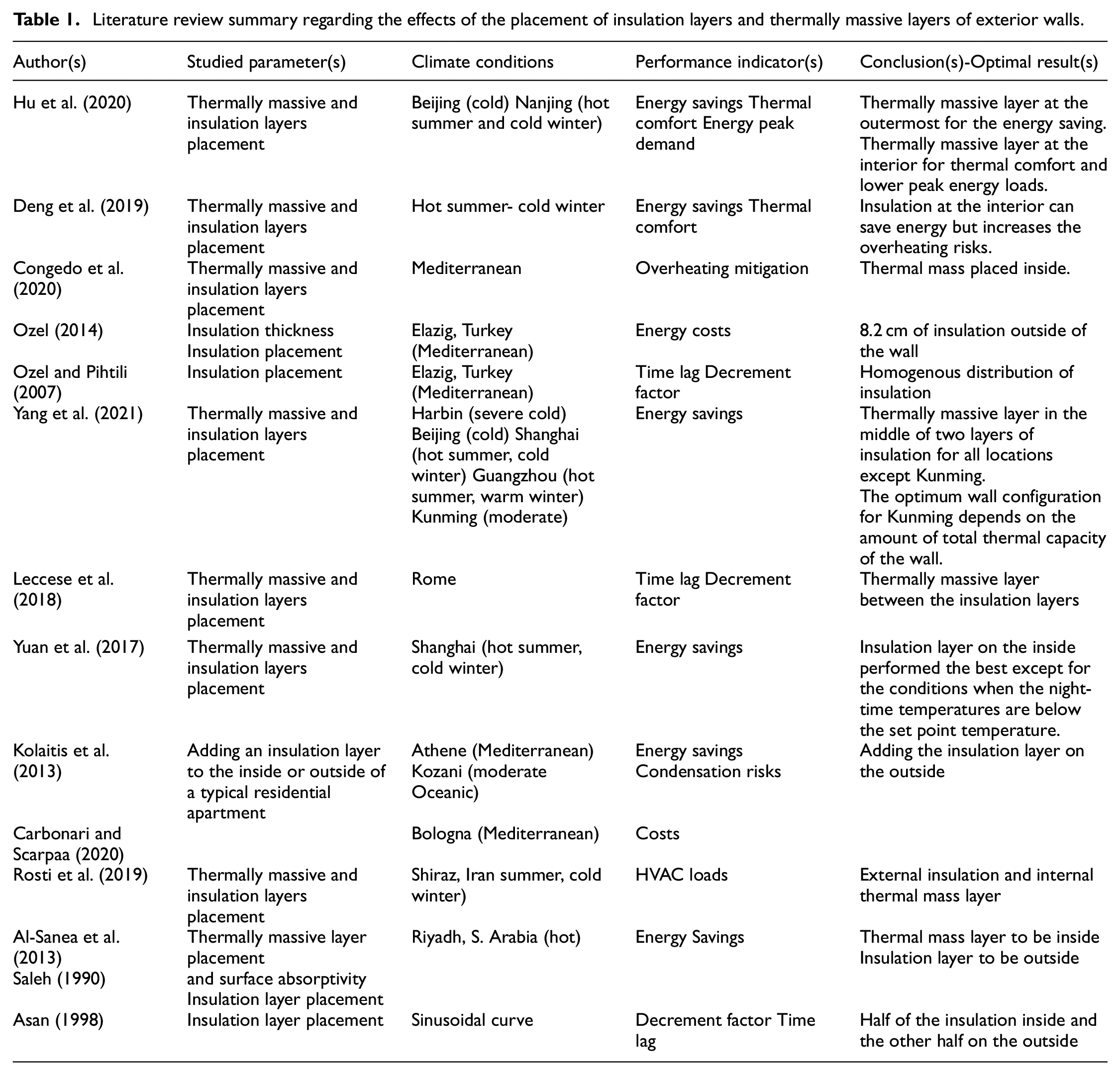
Optimum sequencing of concrete wall layers, which is more relevant to this paper, was also investigated in the literature. Gori et al. (2016) studied the effects of the number of layers and their order of placement within a wall assembly on the decrement factor and time delay assuming that the total thickness of insulation layers, as well as that of the concrete layers, are fixed. Regarding the two-layer walls, it was proven that outside insulation configuration had a lower decrement factor and a higher time lag. On the other hand, denoting the thermally massive layer by C and the insulation layer by I, they found that the decrement factors for ICI and CIC cases with evenly distributed thicknesses are equal under the assumed conditions. Finally, they concluded that IC-configured wall performed better than the ICI-configured wall, meaning that a two-layer wall with outside insulation had a better performance compared to a three-layer wall with a sandwiched insulation layer. By defining ”effective wall heat capacity” parameter, Tsilingiris (2006) investigated the effects of insulation location and distribution within a wall assembly on the transient thermal performance of the walls, specifically the walls’ time constant, as well as the stability of a case study building that is, the building’s capability to delay the impact of a change in outdoor temperature on the indoor air temperature and decrease the indoor temperature swings. It was concluded that the walls’ total thickness did not affect the effective heat capacity as long as the thermal resistance is evenly distributed within the wall. Also, walls whose insulation layers were placed at the inside, outside and in the middle were considered to investigate the effect of insulation location on the effective heat capacity, and it was found that exteriorly-insulated wall had the best thermal performance.
Amongst the concrete-based wall assemblies, Insulated Concrete Form (ICF) and tilt-up walls are two popular assemblies in North American construction. These durable walls have different benefits such as reduced construction time and improved thermal performance due to better airtightness (Saber et al., 2011). The core of an ICF wall contains one layer of concrete sandwiched between two layers of insulation while a tilt-up wall is made of an insulation layer sandwiched between two concrete layers. Two rather similar investigations that considered the thermal performance of the ICF and tilt-up walls were the ones performed by Kosny et al. (1998) and Doebber and Ellis (2005). Considering Minneapolis/Denver (Cold), Washington DC/Atlanta (Temperate), Phoenix/Miami (Hot) as representative climate conditions, they investigated the effects of thermal mass and reduced air-infiltration rate on the total energy demand of a single-storey ranch house by simulating the energy performance of the building. An ICF and 10 wood-frame walls were the case studies for Kosny et al. (1998) while Doebber and Ellis (2005) compared the performances of the building taking a waffle Precast Concrete Panel (PCP), sandwich PCP, conventional wood-frame, highly-insulated wood-frame, and ICF as different case study walls. One consideration for both papers was the assumption of lower air-infiltration rates for the concrete-based walls. It was concluded that the effects of thermal mass and infiltration rate on the energy saving depended on the climate conditions, and that heating and cooling loads due to air leakage were very important.
Investigating the possibility of improving the thermal performance of the buildings by means of thermal mass effect was also seen in other investigations. Considering thermally massive structures typical of Tunisian construction, Daouas (2011) investigated the effects of wall orientation on yearly transmission loads and energy savings potential and found the optimum insulation thickness according to a life-cycle cost analysis. Ekrami et al. (2015) identified strategies and systems for improving the energy performance of the buildings with concrete-based components. Specifically, they mentioned that ICF walls with embodied pipes can have improved thermal performances. Saber et al. (2011, 2010), Armstrong et al. (2011) performed both field tests and thermal performance simulations for two case study ICF walls located in Ottawa, Canada. They found that the benefits of thermal mass was more evident during summers in Ottawa. Also, thermal mass contributed to dampening the fluctuations.
Based on the literature reviewed, the general agreement is that placing the insulation at the exterior layer of the walls improves the thermal performance of the walls and the overall energy use. Performances of various types of thermally massive walls have been assessed in the literature, in terms of both transient thermal performance and energy performance of the buildings that contained these walls. However, the question of what are the effects of placing the thermally massive layer at different parts of a wall on the thermal performance of wall, as well as the energy performance of buildings that contain the wall as part of their envelopes, still exists. In addition, to the best of authors’ knowledge, a descriptive link between the results of the transient thermal performance assessment and those of the whole building energy simulation has not yet been introduced. In this paper, two investigations were performed: (a) using COMSOL Multiphysics© software, assessing the transient thermal performance of four case study walls, namely an ICF wall, a tilt-up wall, a wall made of one homogeneous layer, with its thermal resistance and heat storage capacity being identical to that of the ICF and tilt-up walls, and a wall made of an Expanded Polystyrene (EPS) insulation layer; and (b) simulating the energy performance of a case study office building containing the aforementioned wall assemblies using EnergyPlus© whole building energy simulation tool. Performances are compared and conclusions are made according to the resulting decrement factors, time required to reach quasi-steady state conditions, heat flux and indoor surface temperature amplitude of changes, and heating/cooling demands.
Methodology
One of the objectives of this paper is to find the optimum wall sequencing pattern taking into account both the thermal performance of the walls as separate components and the energy consumption of a small office building. COMSOL Multiphysics© software was used to evaluate the transient thermal performance of the wall assemblies while EnergyPlus© and Openstudio© whole building energy simulation software tools were used to assess the energy performance of a case study office building that has the case study walls as part of its building envelope system. The following sections present the wall cases, as well as governing conditions for each study.
Transient thermal performance of walls
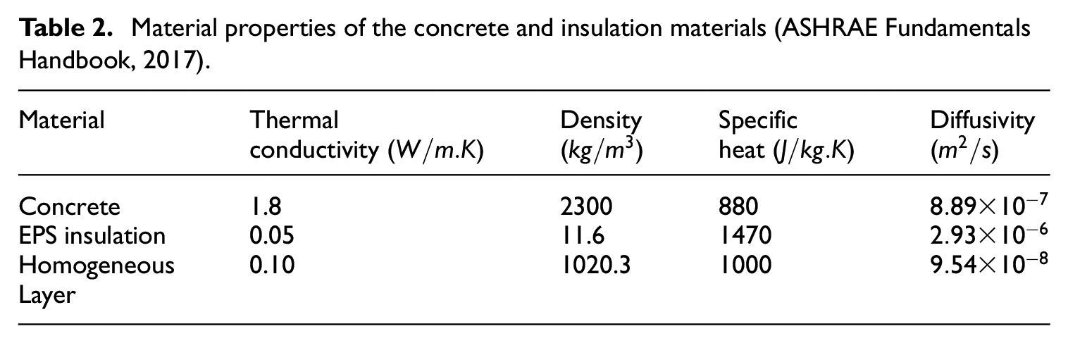
Regarding the assessment of transient thermal performance of walls, three sinusoidal profiles representative of heating-dominated, temperate, and cooling-dominated climates were assumed as the outside temperature conditions. As it can be seen in Figure 1, minimum and maximum values for all temperature profiles occurred at 3 am and 3 pm, respectively. Indoor temperature was maintained at 20°C for all cases. Four case study walls were considered: an ICF wall, a tilt-up wall, a wall with one homogeneous layer (please refer to Table 2 for its thermal properties), and an Expanded Polystyrene (EPS) insulation wall with an identical R-value but different overall thermal storage capacity. ICF wall contains 6 inch (15.24 cm) of thermal mass sandwiched between two 3 inch (7.62 cm) insulation layers while the tilt-up wall case has a 6 inch (15.24 cm)-thick insulation layer sandwiched between two 3 inch (7.62 cm)-insulation layers. The third wall is made of a 12 inch (30.48 cm) thick homogeneous layer, whose thermal properties were modified such that its overall thermal resistance and thermal storage capacity are equal to those of the ICF and tilt-up walls. The thickness of the EPS wall is 6.17 inch (15.67 cm). Schematics of the case study walls can be seen in Figure 2. Concrete and EPS accounted for the thermally massive and insulation materials, respectively. The properties of these materials are presented in Table 2. COMSOL Multiphysics© software was utilized to simulate the heat transfer phenomena through these walls. Indoor and outdoor equivalent convective heat transfer coefficients were set to be 8.33 and 33.33
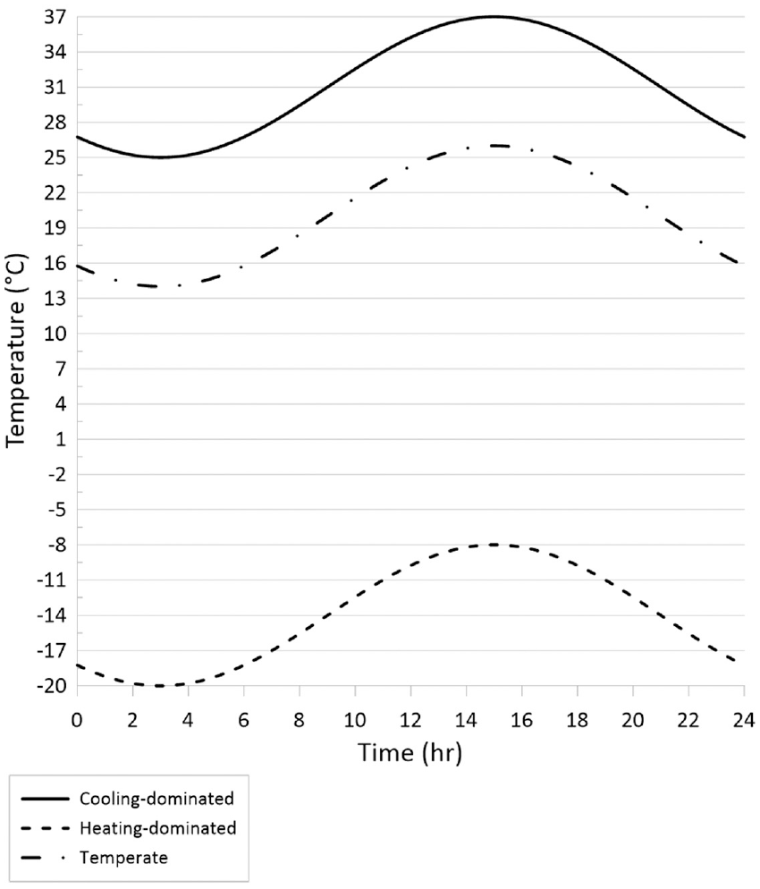
Outside boundary temperatures for one cycle (1 day) for heating-dominated, temperate, and cooling-dominated climate conditions.
Material properties of the concrete and insulation materials (ASHRAE Fundamentals Handbook, 2017).
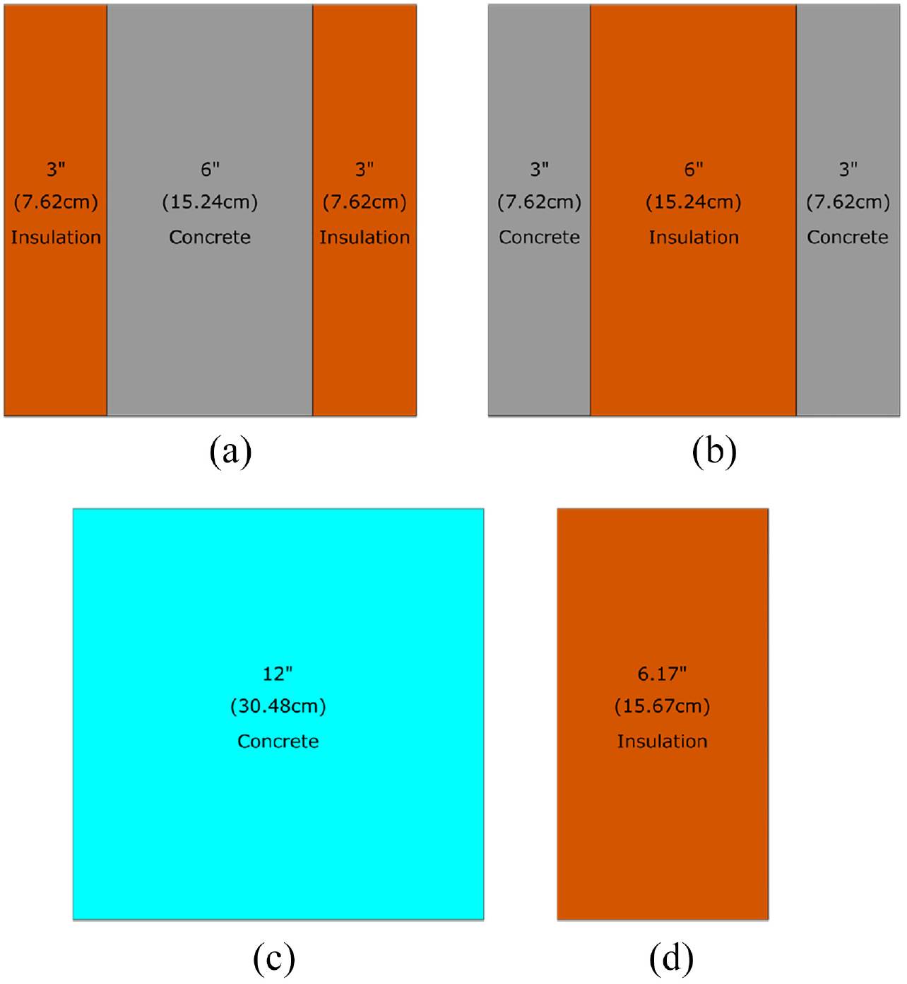
Case study walls: (a) ICF, (b) tilt-up, (c) homogeneous layer, and (d) EPS walls.
Decrement factor
Decreasing amplitude of the thermal wave during its propagation process from outside to inside (Kontoleon and Bikas, 2005). This is an indicator of how much the fluctuations in outdoor conditions are dampened before affecting the indoor conditions.
Time required to reach quasi-steady state conditions
Time (in days) that is required for the stabilization of the heat flux results, and hence to reach quasi-steady state conditions. This parameter is important because it can be an indication of how long the the interior temperature is comfortable for the occupants in case of a power outage.
Amplitude of changes of heat flux and surface temperature of the walls’ interior surface
It is worth mentioning that quasi-steady state conditions refer to the conditions for which the values of heat fluxes are identical to those of the corresponding points in the previous cycle. In this study, the conditions were considered quasi-steady state when the maximum heat flux value within a cycle deviated from that of the last cycle by less than 0.2%. In addition, for the sake of comparison, a criteria of 0.01% for reaching the quasi-steady state conditions was also considered.
Energy performance of a case study office building
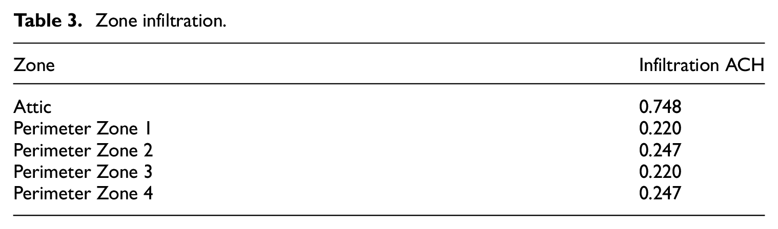
The second step was to assess the energy performance of a one-story office building, schematic of which can be seen in Figure 3. The building is chosen based on the U.S. DOE reference building archetypes for a small office building (U.S. Department of Energy, 2021). The case study building has a total floor area of 511.16
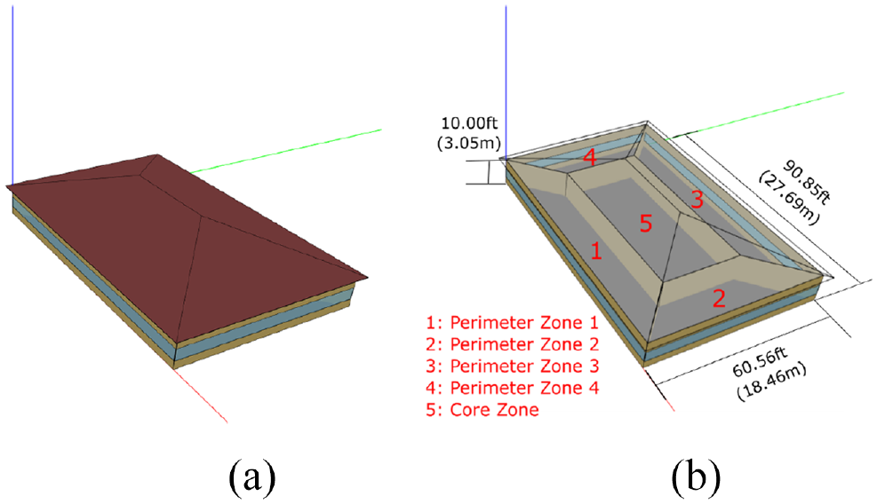
Schematics of the case study building: (a) outside view and (b) representations of the zones.
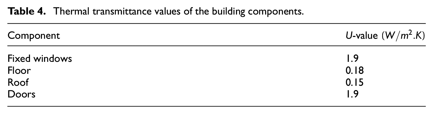
Zone infiltration.
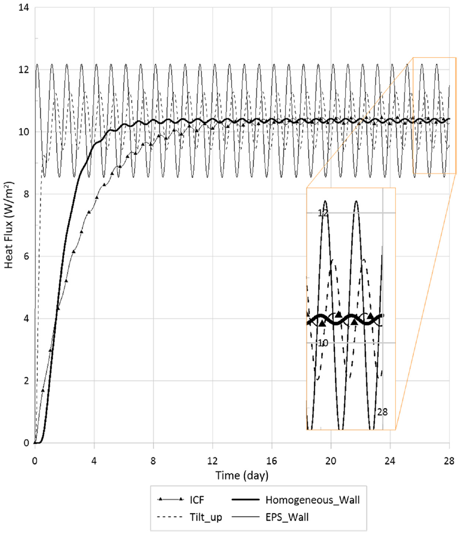
Thermal transmittance values of the building components.
Results and discussion
Thermal performance of the wall assemblies
The first step is to study the transient thermal performance of the walls. In what follows, the results of the heat transfer simulations is presented. They are categorized based on the case study walls and the weather conditions under which the cases were simulated.
Figures 4–6 show the heat fluxes normal to the interior surface of the wall and the values of thermal performance indicators for the four case study wall assemblies under heating-dominated, cooling-dominated, and temperate outside temperature conditions. In addition, Table 5 gives, for each case study wall assembly, total thermal resistance, decrement factor, indoor surface temperature and heat flux amplitudes, and the time required to reach quasi-steady state conditions with the criteria of 0.2%. Since the amplitude of outdoor temperature changes are identical for the three case study weather conditions, the values of performance indicators were identical under all three cases of outdoor temperature conditions. A high amount of time required to reach quasi-steady state conditions means that it takes longer for a change in outdoor conditions to affect the indoor conditions. The number of days needed to reach quasi-steady state conditions for ICF, tilt-up, homogeneous layer, and EPS walls using a 0.01% criteria were 26, 3, 13, and 1 day, respectively. It can be observed that by decreasing the criteria value, the amount of time required to reach quasi-steady state conditions increases. As it can be seen, compared to the other cases, ICF wall required more time to reach quasi-steady state conditions. On the other hand, amplitude of changes of the heat fluxes and indoor surface temperatures were less for the case of the wall with a homogeneous layer, and it has the least decrement factor amongst the cases studied. Comparing ICF and tilt-up walls, although the overall thermal resistances and heat storage capacities are identical, ICF wall required more time to reach quasi-steady state conditions, faced lower fluctuations in its heat fluxes and indoor surface temperatures, and had a smaller decrement factor, as its layer of thermal mass is not directly exposed to the changes in indoor and outdoor temperature conditions. However, it should be noted that the wall with a homogeneous layer with equivalent thermal characteristics is an ideal case, and usually the walls with such configurations either do not exist or are not preferred.
Heat flux transmitted from the interior sides of four case study walls: ICF, tilt-up, homogeneous layer, and EPS walls under heating-dominated temperature conditions.
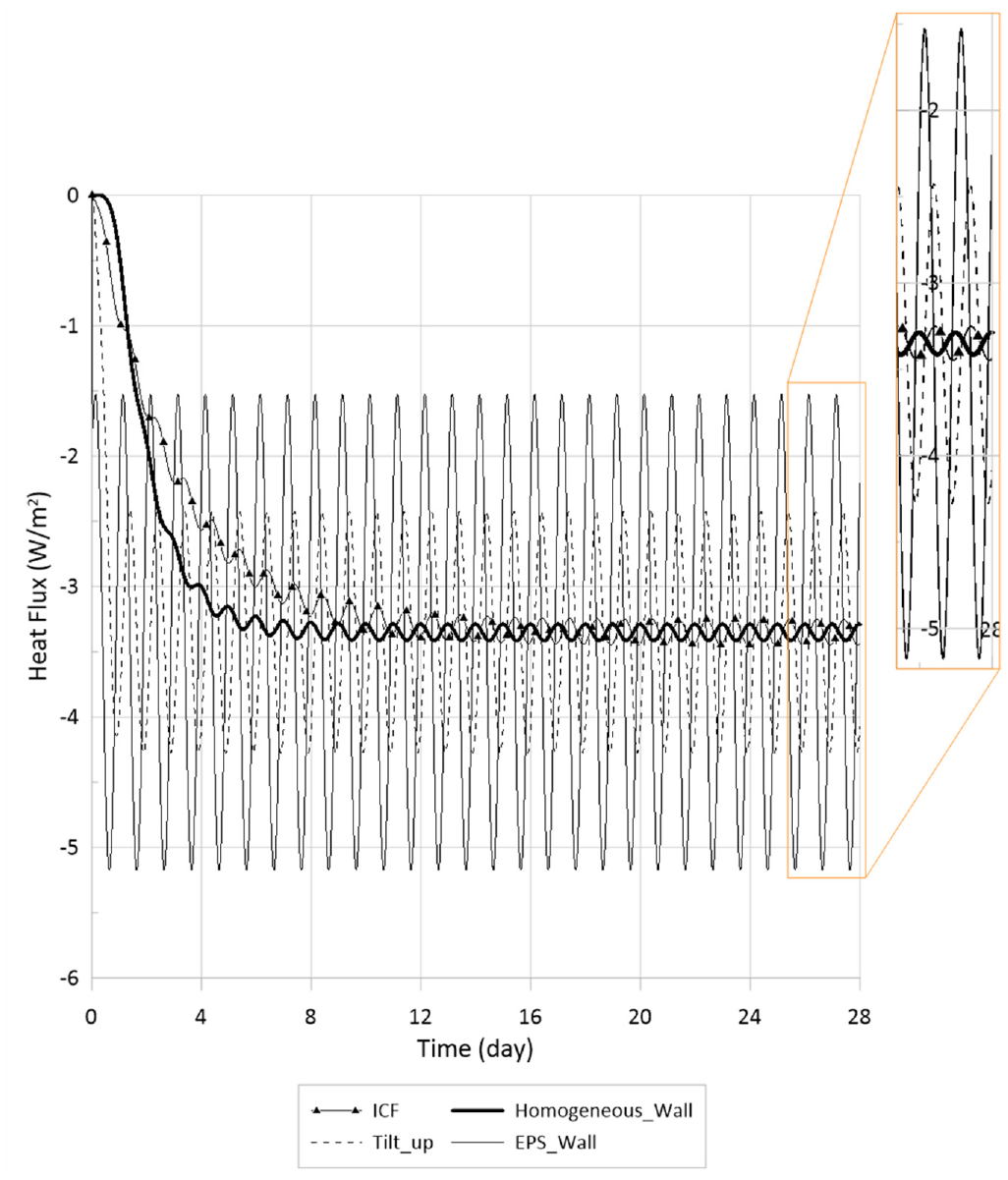
Heat flux transmitted from the interior sides of four case study walls: ICF, tilt-up, homogeneous layer, and EPS walls under cooling-dominated temperature conditions.
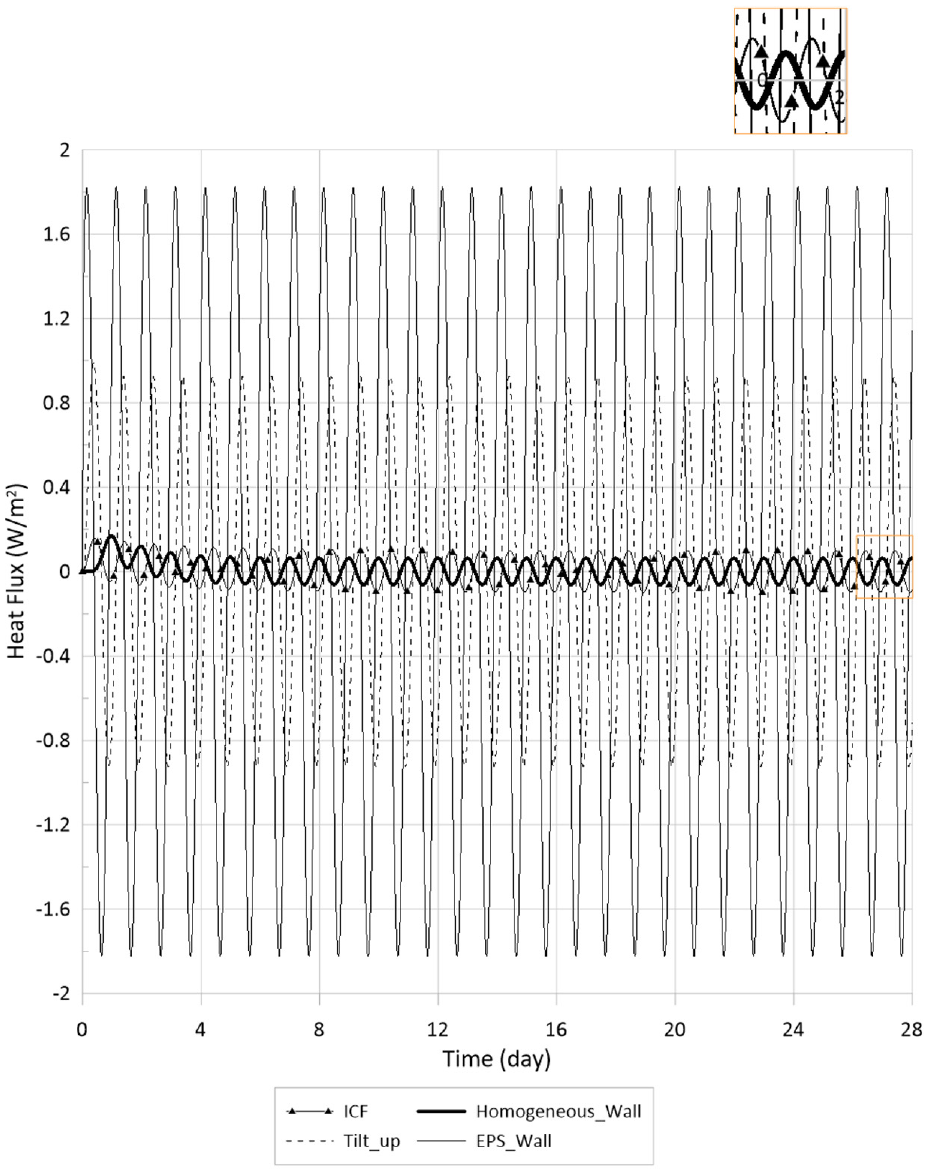
Heat flux transmitted from the interior sides of four case study walls: ICF, tilt-up, homogeneous layer, and EPS walls under temperate temperature conditions.
Thermal performance indicators for four case study walls: ICF, tilt-up, one homogeneous layer and EPS walls under heating-dominated, cooling-dominated, and temperate temperature conditions.
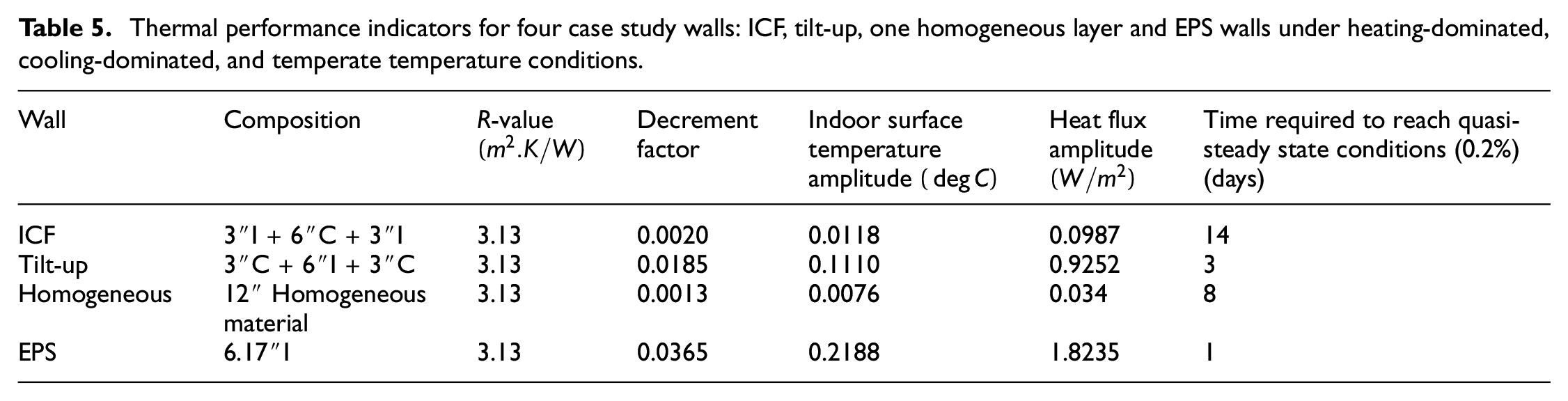
Based on the case studies evaluated, it can be observed that the ICF wall, in which thermally massive layer is not directly exposed to indoor and outdoor temperature fluctuations, had the lowest decrement factor, as well as the amplitude of changes of heat fluxes and indoor surface temperatures, and the highest time required to reach quasi-steady state conditions.
Whole building energy simulation results
The second part of this investigation is the effect of thermally massive layer placement within the wall assemblies on the energy performance of a typical small office building. Climate conditions of three cities were considered, namely Montreal, Denver, and Miami, representative of heating-dominated, temperate, and cooling-dominated climates, respectively. In what follows, these results will be presented.
Case A
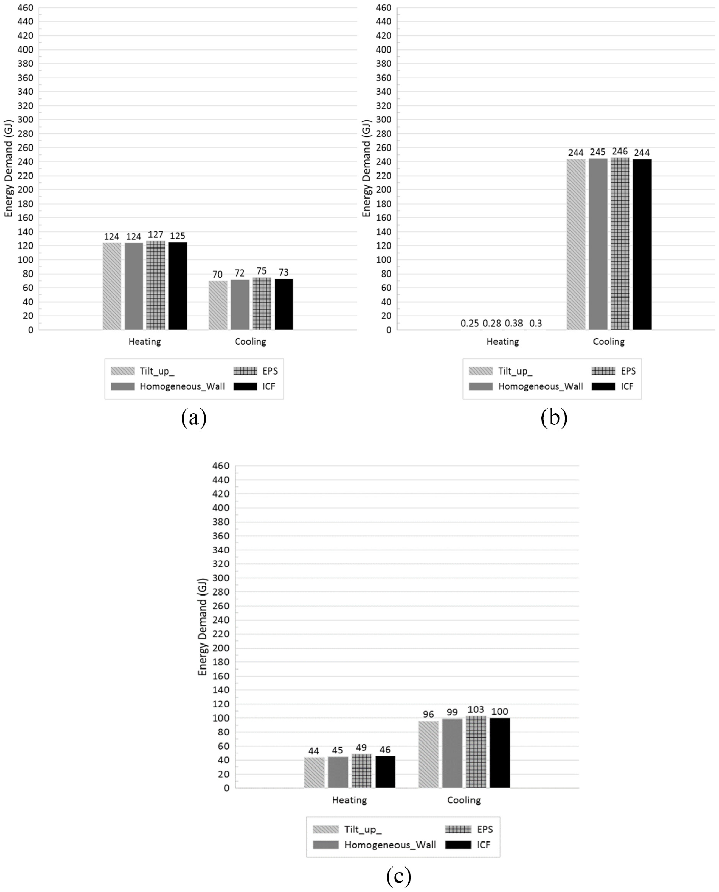
Figure 7 presents the heating and cooling energy demands for the entire building maintaining the indoor temperature at 20°C. It is evident that the heating and cooling energy demands were lower for the building that has tilt-up walls under all three considered climate conditions. However, under each climate condition, minor differences between the resulting heating and cooling demands of the case studies were found. For example, the case with tilt-up walls demanded almost the same cooling energy compared to the ICF case under Miami climate conditions. Although the differences in percentage is higher when comparing heating demands in Miami and cooling demands in Montreal, it should be noted that these loads do not account for a large portion of the total energy demands.
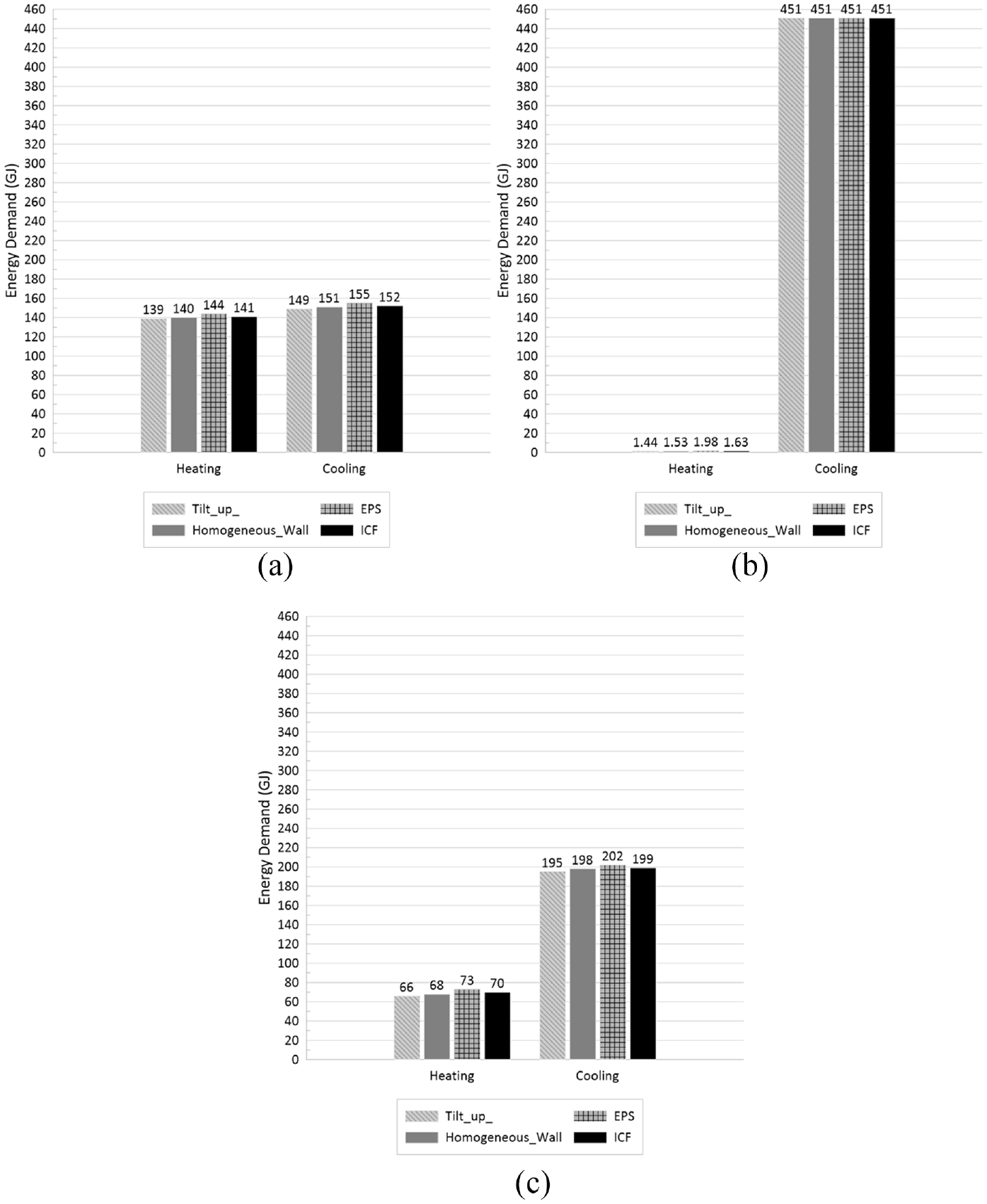
Heating and cooling energy demands under: (a) Montreal; (b) Miami, and (c) Denver climate conditions (Case A).
Case B
Next, the case studies were simulated assuming the aforementioned schedule for the indoor temperature set-point. Figure 8 shows the energy demands for the entire building. It can be observed that the tilt-up case had the lowest energy demands amongst the case studies considered. For example, the case with tilt-up walls demanded 4.1% less cooling energy compared to the ICF case under Denver climate conditions. It can be seen that the differences in energy demands is more tangible under Denver climate conditions, which is a temperate climate. Comparing the results for this scenario with those of the previous one, the energy demands were decreased because in Case A, the thermal zone should be also conditioned during the unoccupied hours, which resulted in a higher energy demand. For example, the ICF case demanded 12.8% less heating energy in Montreal under Case B compared to Case A.
Heating and cooling energy demands under: (a) Montreal; (b) Miami, and (c) Denver climate conditions (Case B).
Effects of the performance of ICF and tilt-up walls on the energy demands
In this section, by presenting the components that contribute to the overall heating and cooling loads, the results for the specific cases of the office building located in Montreal with ICF and tilt-up walls as alternatives of exterior wall assemblies will be discussed. Case A was chosen for the indoor temperature conditions.
To better analyze the sensible heating and cooling demands’ results, firstly, the components that contributed to the hourly heating and cooling loads were identified, which are as follows:
Internal convective heat gain (the heat transfer mode between indoor air and internal heat gain sources (i.e. people, lights, and electric equipment) is purely convective).
Convection and radiation between indoor air and indoor surfaces of walls, roof/ceiling, floor, and windows.
Heat gain/loss due to air transfer (mechanical ventilation and infiltration).
The heating and cooling loads of the perimeter zone 1 (please refer to Figure 3(b)) for the ICF and tilt-up wall cases were chosen as example cases for the sake of comparison and explanation, which are presented in Tables 6 and 7. As expected, the annual heat gain/loss as a result of air transfer and internal gains were identical for both cases, and the differences were due to discrepancies in the convective heat transfer between indoor air and internal surfaces. Heat balance equation for the internal surface of the wall is (US Department of Energy, n.d):

Where:
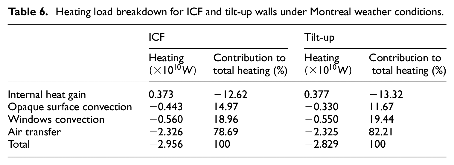
Heating load breakdown for ICF and tilt-up walls under Montreal weather conditions.
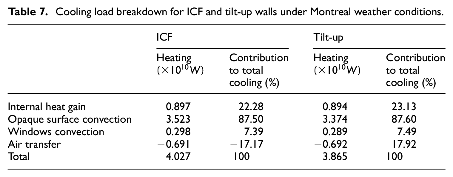
Cooling load breakdown for ICF and tilt-up walls under Montreal weather conditions.
For the case of the office building with ICF walls, the validity of the above equation was evaluated. Maximum discrepancy magnitude was 0.5 W. Hence, the elements of heat transfer for the internal surface can be summarized as follows:
Conduction within the wall assembly.
Convection between the wall’s indoor surface and the indoor air.
Radiation heat gain/loss.
Next, the conduction through the ICF and tilt-up walls were assessed. Figure 9 shows the conduction heat transfer rate per surface area throughout the year. Positive values correspond to the case in which heat flows from internal surface toward the core of the wall while negative values mean that the heat is reaching the internal surface from the core of the wall. It can be seen that the the amplitude of changes of conduction heat fluxes were higher for the tilt-up wall compared to the ICF wall. In addition, as it is shown in Figure 10, the heat transferred from/to the internal surface were lower in both directions for the ICF wall compared to the tilt-up wall. However, the element that determines the heating/cooling loads as a result of heat gain/loss through opaque walls is the convection heat transfer between internal surface of the wall and the indoor air. Figure 11 shows the convection heat transfer rate per wall’s surface area throughout the year. Same as the conduction, positive and negative values correspond to the heating and cooling loads, respectively. As it can be seen, amplitude of changes of convection heat fluxes was higher for the ICF wall case compared to the tilt-up case. Figure 12 shows the resulting heating and cooling energy demand for the ICF and tilt-up assemblies, which were both lower for the tilt-up wall case.
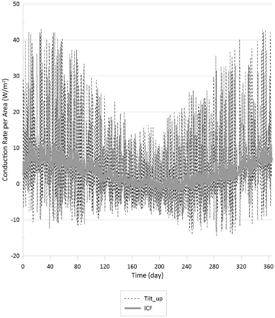
Conduction heat transfer rate per surface area of the wall for ICF and tilt-up assemblies.
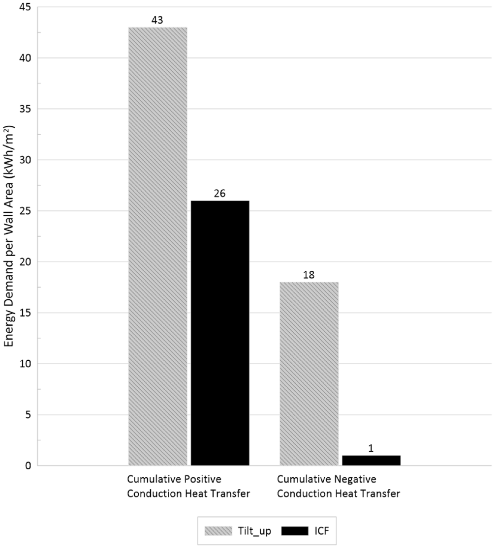
Cumulative positive and negative conduction heat transfer for the ICF and tilt-up walls.
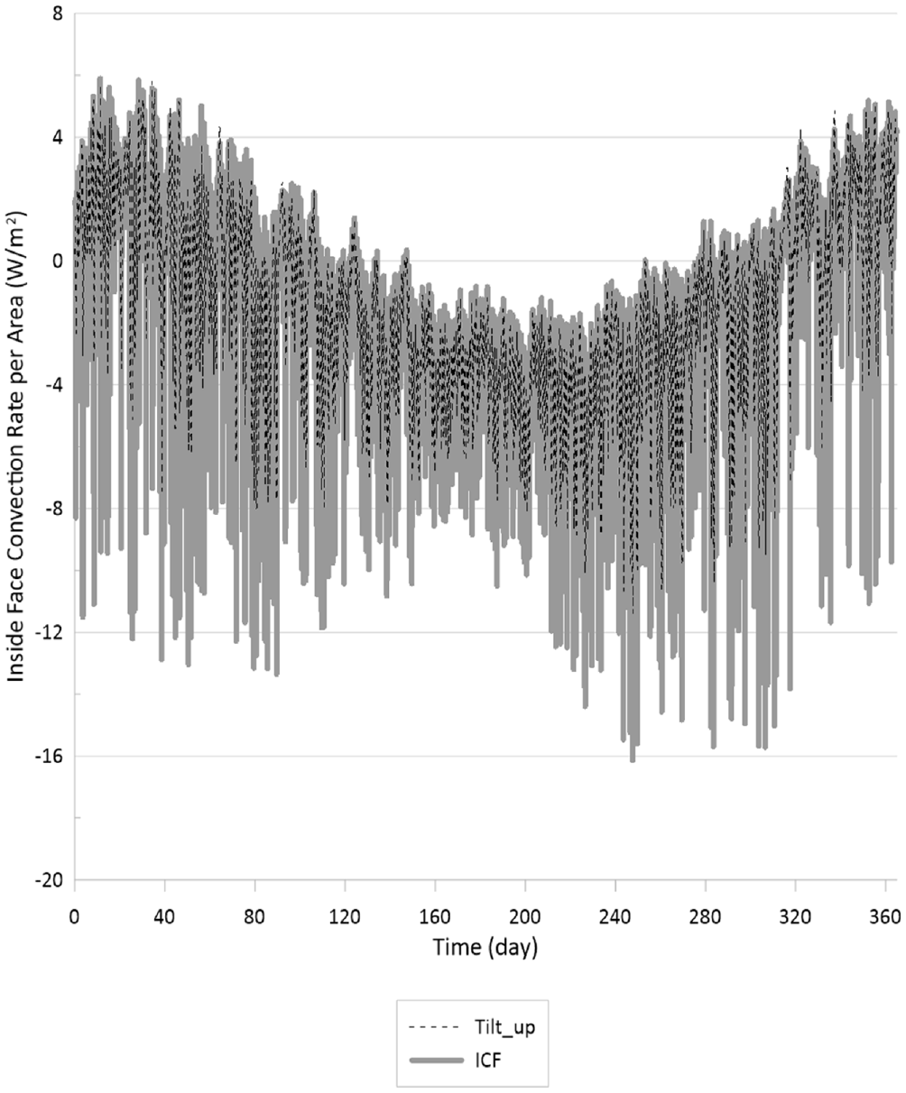
Convection heat transfer rate per wall’s surface area for the ICF and tilt-up walls.
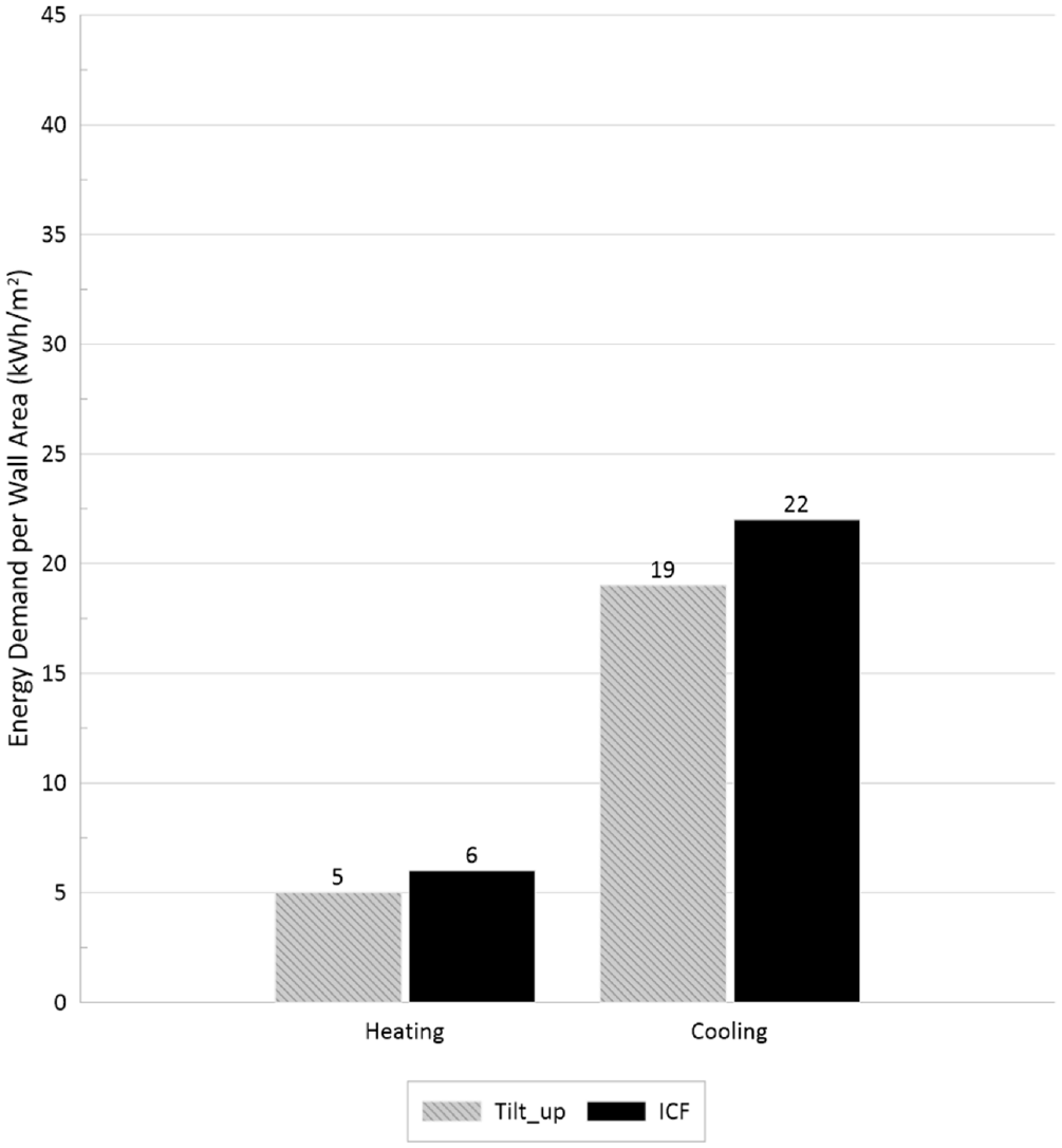
Heating and cooling loads as a result of convection heat transfer between internal surface of the wall and the indoor air.
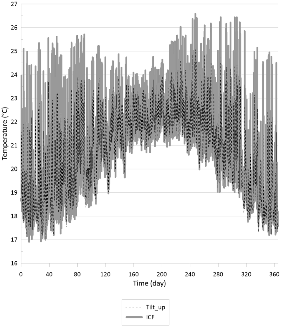
To better understand the reasoning behind the results, internal surface temperature should be monitored more closely. Figure 13 represents the annual indoor surface temperatures for the ICF and tilt-up walls. It can be seen that the amplitude of changes of the internal surface temperature was smaller, which resulted in lower heating/cooling loads. On the other hand, Figure 14 presents the heat convection, conduction, and indoor surface temperature for January 1st and January 2nd for the ICF and tilt-up wall cases. Time lag between the indoor surface temperature and heat conduction from the internal surface of the ICF wall was smaller than that of the tilt-up wall.
Internal surface temperature for the ICF and tilt-up walls.
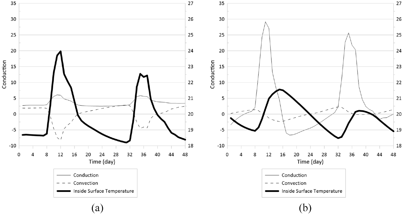
Heat conduction, convection, and internal surface temperature for: (a) ICF wall and (b) tilt-up wall.
Although the amplitude of changes of conduction heat fluxes from the internal surface of the ICF wall was smaller compared to the tilt-up wall, the convection heat transfer between the internal surface of the ICF wall tends to fluctuate more compared to the tilt-up wall. Firstly, it should be noted that for the ICF wall, 51% of the total R-value of the wall is between surface 2 and surface 4, while for the tilt-up wall, 98.6% of the total R-value of the wall is between surface 2 and surface 4 (please refer to Figure 15). It should be noted that the diffusivity of the EPS insulation material is higher than that of the concrete layer because of its low thermal conductivity, density, and heat storage capacity compared to the concrete material whose thermal conductivity is higher but its heat capacitance is much higher (please refer to Table 1). Although the resistivity of the first layer in the tilt-up wall is lower than that of the ICF wall, it can store more energy due its higher thermal capacity and hence, can flatten the temperature fluctuations on the inner layer’s surface. From 8 am until 5 pm, the thermal radiation incident on the internal surface of the wall increases (as a result of people’s presence, lights’, and equipment’s heat generation, and solar radiation). This incident heat can be transferred toward the outer surface of the wall, be stored inside the innermost layer, or increase the temperature of the layer. As for the ICF case, given that the R-value of the innermost layer is rather higher, the heat cannot easily flow toward the outer layers. On the other hand, the thermal storage capacitance of the EPS layer is negligible. As a result, the temperature of the internal surface of the wall increases, and the heat is conducted from the inner surface toward the thermally massive layer, which is located at the middle of the wall. Also, because the temperature of the internal surface of the wall is higher than the indoor air temperature for most of this period, the heat is dissipated back to the indoor air. The heat dissipation from the internal surface, as well as the decrease of the outdoor temperature, decreases the surface temperature, and as a result, the convection from the indoor air increases during nighttime. In conclusion, the negligible thermal storage capacity of the innermost layer and its high thermal resistance for the ICF wall led to a larger amplitude of changes of wall’s internal surface temperature and interior convection heat fluxes.
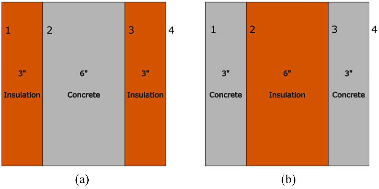
ICF and tilt-up walls with numbered surfaces: (a) ICF and (b) tilt-up walls.
As for the tilt-up wall, on the other hand, the innermost layer has a high heat storage capacity and a rather low thermal resistance. As a result, the incident heat radiation can be stored in the concrete layer, and the surface temperature does not change rapidly within the period of 8 am to 5 pm. On the other hand, the surface temperature is higher during nights, and whenever the surface temperature is decreasing, the stored heat is conducted back toward the inner surface to compensate for the heat loss (or lack of heat radiation for maintaining the temperature). Hence, the internal surface temperature of the wall is maintained within a more stable range compared to that of the ICF wall, and as a result, the heat convection between the wall and indoor air decreases. In conclusion, given the high amount of thermal mass and rather low R-value of the innermost layer for the tilt-up wall case, heat can easily flow and be stored, and the amplitude of changes of inner surface temperature is smaller, which in turn leads to a lower and more stable convection heat transfer.
Conclusion
In this paper, the effects of different placements of the thermally massive layer within the wall assemblies on the transient thermal performance of the wall assemblies and the energy performance of a case study office building were assessed. Specifically, the wall configuration which had the smallest decrement factor, the minimum amplitudes of changes of internal surface temperature, the slightest fluctuations of heat fluxes, and the maximum time required to reach quasi steady-state conditions was firstly found. Then, the case which led to the minimum heating and cooling energy demands was identified. Four wall assemblies were chosen, namely an ICF wall, a tilt-up wall, a wall made of an EPS insulation layer, and a wall made of a homogeneous material with equivalent thermophysical properties. The thermal resistance of all these walls were identical, and except for the EPS wall, total thermal capacitance of the assemblies were also identical.
Firstly, using COMSOL Multiphysics© software, transient thermal performance of these case study walls were investigated under three outdoor sinusoidal temperature conditions: (i) heating-dominated conditions with minimum and maximum values of −20°C and −8°C, respectively, (ii) temperate conditions whose minimum value was 14°C while the maximum value was 26°C, and (iii) cooling-dominated conditions whose minimum and maximum temperature values were 25°C and 37°C, respectively. It was found that, under the case study climate conditions, the wall made of the homogeneous material had the lowest decrement factor of 0.0013 (compared to 0.002, 0.0185, and 0.0365 for ICF, tilt-up, and EPS walls, respectively) and the smallest heat flux and indoor surface temperature amplitudes of changes. ICF wall had the highest amount of time required to reach quasi-steady state conditions (14 days compared to 1 day for EPS wall and 3 days for tilt-up wall) that is, a change in outdoor temperature conditions affected the indoor conditions with more delay. Comparing the performance of the ICF and tilt-up walls, although the overall thermal resistance and thermal capacitance of the ICF wall were identical to those of the tilt-up wall, the ICF wall had smaller decrement factor, as well as the amplitudes of changes of interior surface temperature and heat flux, and required longer time to reach quasi steady-state conditions. It should be noted that, for the cases studied, the choice of wall type can have a significant effect on the decrement factor and the time required to reach quasi-steady state conditions while the amplitude of changes of walls’ indoor surface temperature varied between 0.0076°C (for homogeneous wall) and 0.2188°C (EPS wall). On the other hand, amplitude of changes of heat fluxes from indoor surfaces of the walls highly depended on the wall choice as it ranged between 0.0634
Secondly, using OpenStudio© and EnergyPlus© whole building energy simulation software tools, the energy demands of a case study office building were compared for the cases containing the aforementioned walls under the weather conditions of three cities: (i) Montreal as a representative of a heating-dominated climate, (ii) Denver as a representative of a temperate climate, and (iii) Miami as a representative of a cooling-dominated climate. Two scenarios for the indoor temperature conditions were assumed: (A) the indoor temperature is maintained at 20°C throughout the year and (B) during wintertime, the indoor temperature is 22°C during people’s presence and 18°C during the rest of the time while during summertime, the indoor temperature is maintained at 24°C during people’s presence and there is a setback of 35°C. Under these three climate conditions and for both indoor air temperature scenarios, the case containing tilt-up walls performed better while the case with EPS walls had the highest heating and cooling demands. For example, under case B for indoor setpoint temperature scenario and Montreal weather conditions, the building with tilt-up exterior walls had 6.6% lower cooling demand and and 2.3% lower heating demand compared to the case with EPS walls. This showed the importance of thermal mass as a mean to reduce the energy demands of the case study office building. Comparing the energy performances of the ICF and tilt-up cases, under the first indoor air temperature scenario, maximum energy savings was for heating in Denver, for which the tilt-up case demanded 6% less heating energy. On the other hand, under the second indoor air temperature scenario, tilt-up case, compared to the ICF case, demanded 4.5% and 4.2% less heating and cooling energies in Denver, respectively. In addition, amplitude of changes of the indoor surface temperature was lower for the tilt-up wall case. The archetype with the case study homogeneous wall demanded more energy compared to the tilt-up case but less energy compared to the other cases under the three climate conditions and for both indoor air temperature scenarios. For instance, under case B for indoor temperature setpoint and Miami climate conditions, homogeneous wall case required 0.4% more cooling and 12% more heating energy compared to the case with tilt-up exterior walls. It can be concluded, based on the cases studied, that placing the thermally massive layer at the interior side of the wall can reduce the energy demand of the case study office building. However, the energy savings are not considerable. Having said this, the authors acknowledge that for taking the decision of where to place the thermally massive layer, the hygrothermal performance of the building should be taken into account, and the current study is the first step toward taking this decision.
Footnotes
Declaration of conflicting interests
The author(s) declared no potential conflicts of interest with respect to the research, authorship, and/or publication of this article.
Funding
The author(s) received no financial support for the research, authorship, and/or publication of this article.