
Abstract
Traditional visual-inertial simultaneous localization and mapping algorithms are usually designed based on CPUs, and they cannot effectively utilize the parallel computing function of GPUs if they are directly transplanted to an embedded board with a GPU module. However, the computing power of embedded devices is limited. It is unreasonable for the visual-inertial simultaneous localization and mapping algorithm to occupy most CPU computing resources while the GPU is idle. In this article, a parallelization scheme for the VINS-Mono algorithm based on GPU parallel computing technology is proposed. Based on the compute unified device architecture, the construction and solution of the incremental equation are parallelized in the nonlinear optimization process of the algorithm, and the parallelization methods provided by cuSOLVER and cuBLAS are used to carry out the marginalization of the algorithm. In addition, the program for the detection and matching of image feature points in the process of optical flow tracking is rewritten in the algorithm to realize the parallelization of optical flow tracking. After parallelization, the algorithm is found to run well on a heterogeneous computing model composed of a CPU and GPU and can fully exploit the parallel computing power of the GPU. The proposed method was tested on an NVIDIA’s Jetson TX2 module and compared with the VINS-Mono algorithm; the speeds of the construction and solution of the incremental equation were found to be the same, but the optical flow tracking and marginalization speed of the proposed scheme exhibited improvements of about 1.5–1.7 times and 1.9 times, respectively.
Introduction
The simultaneous localization and mapping (SLAM) algorithm is widely used in the field of autonomous driving and intelligent devices, such as autonomous mobile robots and unmanned aerial vehicles (UAVs), and has undergone great development in recent years. 1 The visual-inertial simultaneous localization and mapping (VI-SLAM) algorithm fuses the measurement data of a camera and the inertial measurement unit (IMU) as the algorithm input and obtains the optimal estimation of the carrier pose based on filtering 2 –6 or an optimization algorithm. 7 –9 It extracts feature points from the images of surroundings collected by the camera. The two-dimensional (2D) coordinates of these feature points in the images are all the mapping of a specific three-dimensional (3D) coordinate in the environment. After finding the feature points that map the same 3D coordinate in the environment in two frames of images, the relative pose between the cameras at the two moments of the two frames can be calculated based on the multi-view geometry method. 10 In addition, a six-axis IMU can measure the local linear acceleration and angular velocity of the carrier, and the integral of the measured acceleration and angular velocity can initially estimate the posture change of the carrier. Further, to improve the accuracy of the algorithm, the bundle adjustment (BA) optimization method is used to improve the accuracy of the calculation of the relative pose of the two images. BA is the application of the nonlinear least-squares method in the field of multi-view geometry. By minimizing the reprojection error between the feature points and landmark points, the optimal estimation of the camera pose and the 3D coordinate of a landmark can be obtained. 11 Similarly, the nonlinear least-squares method can also be used to improve the accuracy of the carrier pose based on the integration of IMU measurement data.
It is easy to parallelize image feature extraction and matching, and a GPU has better parallel computing capability than a CPU. To improve the utilization rate of the GPU module when executing the SLAM algorithm on embedded devices, the process of image feature extraction and matching in the algorithm should be migrated to GPU devices. In addition, nonlinear optimization consumes the most resources among the components of the VI-SLAM algorithm. If the nonlinear least-squares method is parallelized based on a GPU and migrated to the GPU for execution, the GPU utilization ratio of the SLAM algorithm can be effectively improved. In the SLAM algorithm, to avoid the constant increase of the number of state variables involved in the nonlinear optimization problem, the state variables to be discarded are usually marginalized based on the Schur complement theory. 12 To improve the speed of the marginalization operation, parallel processing is also required for the computation.
The VINS-Mono 7 algorithm is a VI-SLAM algorithm that combines a camera and IMU sensors. The front end of the algorithm extracts the feature points that map the same 3D coordinate in two image frames based on the optical flow method, and then calculates the relative pose of the two image frames. Moreover, based on the integration of the IMU measurement data, the pose estimation of the carrier can also be conducted. Loosely coupled initializations are carried out for these two measurements. After successful initialization, initial estimates of the carrier’s initial velocity, gravitational acceleration, scale factor, and gyroscope bias in the IMUs can be obtained. The back end of the algorithm is based on the sliding window method. In one window, the IMU measurement data and camera measurement data are combined for tightly coupled nonlinear least-squares optimization, which endows the algorithm with good accuracy. However, the algorithm is designed entirely based on a CPU and cannot take advantage of the parallel computing power of a GPU when transplanted to an embedded board with a GPU module.
Because the data must be transferred between host memory and GPU memory, there is an additional time cost to parallelizing the algorithm and porting it to run on the GPU. It limits the real-time performance of parallelized algorithm. The ratio of the time taken to transfer data between host memory and GPU memory in the total algorithm running time is one of the key factors to accelerate parallel computing using GPU. In order to ensure that the parallelized algorithm can run in real time, the program must be carefully designed to make the data transfer operation as few as possible. In the VI-SLAM algorithm, not all steps need to be parallelized. We must balance the GPU utilization with the real-time performance of the algorithm. For the steps with less computation in the algorithm, they should be run on the CPU.
This article proposes a parallelization scheme of VINS-Mono. Based on a GPU, the optical flow tracking, nonlinear least-squares optimization, and marginalization program of VINS-Mono are parallelized. When the proposed algorithm runs on embedded devices with a GPU module, it can fully utilize the parallel computing power of the GPU. The CPU module of the device will not be occupied by VI-SLAM algorithm, and there are remaining computing resources for other main tasks, so as to improve the portability of VI-SLAM algorithm in embedded devices. The main contributions of this article include the following. Based on a GPU, the optical flow tracking, nonlinear least-squares optimization, and marginalization program of the VINS-Mono algorithm are parallelized. The result of the experiment demonstrates that the proposed algorithm can run in real time on NVIDIA’s Jetson TX2 module, and the marginalization and optical flow tracking speeds of the algorithm are improved by about 1.5–1.7 times and 1.9 times, respectively, after parallelization. The proposed scheme improves the portability of VINS-Mono on embedded devices.
Related work
In recent years, industries such as autonomous mobile robots and UAVs have boomed and gained increasing market attention, which has also promoted the development of related technologies, such as SLAM. The SLAM algorithm can be applied to autonomous mobile robots and UAVs as the basis of their localization and navigation algorithms. Because the power consumption of robots and UAVs must be reasonably controlled to extend their battery life, embedded boards are more likely to be used as their control and calculation modules. However, as a computationally intensive algorithm with high requirements for computational accuracy, SLAM often has high requirements for the floating-point computing capability of computing devices, and it is difficult for ordinary embedded devices to run SLAM algorithms in real time. 13 –15 For embedded devices equipped with GPU modules, it is expected that the real-time performance of the SLAM algorithm can be improved if a portion of the computation is migrated to GPU.
In the VI-SLAM algorithm, the feature extraction and matching process of environmental images collected by a camera is a computational process that can easily be parallelized. Based on the compute unified device architecture (CUDA), Aldegheri et al. carried out the parallelization of the ORB-SLAM2 16 algorithm; their method involved the calculation and matching of oriented FAST and rotated BRIEF (ORB) descriptors on the GPU so that it could run on the Jetson TX2 module in real time. 17 Huang et al. proposed a 3D reconstruction method based on GPU parallel computing technology, which uses a GPU to conduct the image feature extraction and matching process, thereby effectively improving the speed of 3D reconstruction on embedded devices. 18 However, these methods only focus on the parallelization of feature extraction and matching, and migrate this process to the GPU device; they do not migrate the nonlinear optimization part of the algorithm, so the parallel computing power of the GPU in the embedded device is not fully exerted. The nonlinear least-squares optimization module in the SLAM algorithm requires a large amount of computation. More importantly, some of these computations do not have any correlation, which makes it possible to parallelize this module. Wu et al. proposed a parallelized BA method in which the Levenberg–Marquardt (LM) algorithm is used to iteratively optimize the estimation of the position and direction of a camera. In the process of algorithm iteration, the preconditioned conjugate gradients (PCG) algorithm is used to solve the incremental equation. By focusing on improving the multiplication speed of some matrices and vectors in the PCG algorithm, the algorithm can make use of the parallel computing power of GPUs to achieve algorithm acceleration on performance-grade GPU devices. 19 However, the algorithm only shows the processing results of single-precision floating-point data; the numerical size of the data involved in the SLAM algorithm may even exceed the representation range of single-precision floating-point data in computers. Although data normalization is adopted in the algorithm to solve this problem, 19 the accuracy of the algorithm is inevitably affected by data types. In the field of lidar SLAM, some studies have been conducted on parallel algorithms based on GPUs. For example, Ratter et al. parallelized the iterative closest point algorithm based on GPUs in their proposed lidar SLAM scheme. 20
When using optical flow to track two image frames, it is first necessary to extract the feature points in the frames, and then to match the feature points according to the assumption of constant luminosity to achieve tracking. Moreover, for both the extraction and matching of feature points, the calculation of each feature point can be carried out in parallel based on GPUs. In addition, the correlation calculation of each residual component in nonlinear optimization can be carried out in parallel. The parallelization method provided by cuSOLVER and cuBLAS is used to parallelize the Schur complement matrix operation in the process of marginalization, which can also realize the effective utilization of GPU resources.
The proposed method focuses on the parallelization of VINS-Mono based on a GPU. The method mainly includes the parallelization of optical flow tracking, nonlinear least-squares optimization, and the marginalization process. By running the parallelized algorithm on an embedded device with a GPU, the GPU module of the device can be effectively utilized, and avoid the GPU on the embedded device being idle, so that the computational resources of the hardware can be allocated more reasonably.
Method
This section introduces the details of the proposed framework.
Nonlinear optimization in VI-SLAM
In the VI-SLAM algorithm, the solution of the pose of the camera and the 3D coordinates of landmark points is a problem of state estimation, that is, the optimal estimations are obtained from observed data with noise. When the probabilistic model of noise is modeled as a Gaussian distribution, the maximum likelihood estimation of the 3D coordinates of the camera pose and landmark points is essentially a nonlinear least-squares problem. Specifically, the following errors must be minimized in each sliding window: the IMU measurement residuals; the reprojection error; and the priori error left by marginalization.
It should be noted that the prior information is left by the marginalized pose after each marginalization, so it is necessary to continue to optimize the prior items in each sliding window. In this problem, the following state variables must be optimally estimated

where

where
Moreover,

The objective function of the problem is as follows

where rp
is the priori error, and Jp
is the first derivative of the prior error with respect to X. rB
is the IMU measurement error, and rC
is the reprojection error.
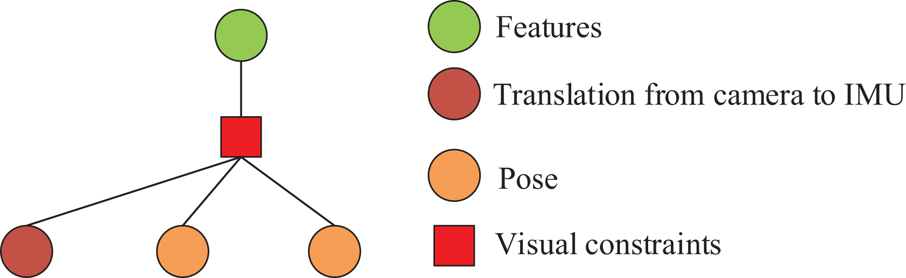
The objective function can be analyzed more intuitively via a factor graph. As shown in Figure 1, an IMU measurement corresponds to four edges in the factor graph. The camera pose, carrier speed, and IMU bias of two adjacent image frames constitute the vertices attached to these edges, which correspond to an IMU residual calculation in the following objective function


The factor graph of nonlinear optimization. The calculations on each edge of the factor graph are only related to the vertices corresponding to each edge and do not depend on the calculations on other edges.
The observation of a certain landmark point between two key frames corresponds to four edges. The inverse depth of a landmark point, the pose of two key frames, and the relative pose between the camera and the IMU constitute four vertices of these edges. This corresponds to the calculation of a reprojection error in the objective function, as follows

Marginalization leaves a priori error in the sliding window corresponding to the following parts of the target function

It can be seen that the calculations involved in each edge of the factor graph are only related to the vertices corresponding to each edge, and there is no dependence on the calculations of other edges. The parallelization of the nonlinear optimization of VINS-Mono in this study is completed based on the calculations involved in the parallel execution of each edge.
CUDA is a set of programming interfaces provided by NVIDIA, based on which it is convenient to allocate GPU computing resources. In the proposed method, the data transmission between the CPU and GPU is based on CUDA. The data required for parallel computing are copied from the host memory to video memory, and the final result is obtained by completing the calculation on the GPU. The result is then transferred to the host memory and handed to the CPU to complete the subsequent process of the SLAM algorithm.
Construction and solution of the incremental equation
The LM algorithm is often used to iteratively determine the optimal estimator in least-squares problems. The following incremental equation must be solved at each iteration

where J is the first derivative (Jacobian matrix) of the objective function to the optimized state vector,
Moreover, α is always greater than zero during iteration. The incremental equation can be written in the following continuous form

where O is the set of all observations, including IMU measurements and camera measurements, and the components of the incremental equation are calculated in parallel on each observation and summed up to obtain the total incremental equation. Ji
, ri
, and
Our approach focuses on parallelizing VINS-Mono without changing its mathematics. The related calculation for reprojection error in the objective function can be represented by the factor graph shown in Figure 2. In VINS-Mono, the calculation of a reprojection error component in the objective function and its first derivative with respect to the relevant state variables involves the inverse depth of landmark points (
The factor graph of reprojection error. The reprojection error corresponds to four edges.
The single-instruction multiple-data (SIMD) model was used to write the program. In CUDA, each thread executes the same kernel function in parallel with different data. In the kernel function, the residual or Jacobian matrix of one measurement is computed. When multiple threads execute the kernel function in parallel, all residual or Jacobian matrix calculations are completed.
Table 1 describes the parallelization calculation method of J and r related to the reprojection constraint. Since the GPU memory cannot be initialized directly in CUDA, the program needs to allocate continuous space and assign values in the host memory, and then transfer the data to the GPU memory.
Parallel calculation of J and r in reprojection constraint.

As shown in Figure 3, before the parallel execution of the kernel function is initiated on the host side, the data on which the calculation depends must be copied from the host memory to video memory. In the video memory, a one-dimensional array is used to store these data. The kernel function calculates the index of the required data in the array with the thread ID, and then reads the data from the GPU video memory to complete the calculation of the Jacobian matrix and residual.

The flow of data required in calculations related to reprojection constraints. The proposed program records the connection relationship between edges and corresponding vertices in the factor graph when constructing the least-squares problem.
The calculation related to the IMU measurement in the objective function can be represented by the factor diagram in Figure 4. The calculation process is related to the camera pose, carrier velocity, and IMU bias of the two image frames involved in the IMU measurement.

Factor graph of IMU constraints. IMU: inertial measurement unit.
The parallel mechanisms of IMU measurement and reprojection are the same, and only the data stored in the memory are different. Because the increment of the IMU measurement error is linearly related to the IMU bias in the hypothesized iterative optimization process of VINS-Mono, the calculation process requires the first derivative of the error increment to the IMU bias, the pose increment calculated in the pre-integration process, the velocity increment, and the linearized IMU bias.
After the Jacobian matrix and residual calculation on each measurement are completed in parallel, the coefficient matrix of the incremental equation can be constructed as follows

Moreover, the right side of the incremental equation is as follows

Both the matrix H and the vector b on the right side of the incremental equation are superimposed by multiple components. Therefore, each component is first computed in parallel, and the superposition operation of the matrix
The final stacking process involves multiple threads writing data to the same memory, which is extremely unsafe. CUDA provides atomic functions for the queuing of multiple threads to access the same memory address. However, sequential writes to the global memory via multithreading can also be time-consuming. Because the shared memory access of the GPU is faster, a natural idea is to perform atomic operations on the shared memory and then copy the results of the computation to the global memory. Because the shared memory capacity of the GPU is not sufficient to calculate the entire coefficient matrix, the coefficient matrix is partitioned.
As shown in Figure 5, the coefficient matrix can be divided into four parts, where Hpp is the approximate second derivative of the objective function to the camera pose, carrier velocity, and IMU bias.

The partitioning of the coefficient matrix. The coefficient matrix can be divided into four parts according to the arrangement rules of elements in the state vector and the relationship of each element in the factor graph.
Finally, the following equation is obtained

According to the characteristics of the SLAM problem, in the equation, H is a symmetric semi-positive definite matrix, and α is always greater than zero in the iterative process of the LM algorithm. Therefore, the coefficient matrix of the equation is a symmetric positive definite matrix, and the solution can be effectively accelerated by using the following Cholesky decomposition

CUDA provides users with a parallel Cholesky decomposition tool. Based on CUDA’s cuSOLVER function library, the parallel solution of the incremental equation is realized.
Marginalization
The sliding window algorithm is used to control the computational complexity of the back-end nonlinear optimization module. Specifically, the old variable must be removed from the sliding window, but if it is directly removed, useful information will be lost. For a SLAM problem in which the probability model is modeled as a multivariate Gaussian distribution, the correct way to remove the old state variables is to marginalize them based on the Schur complement. Before marginalization, the components of the incremental equation corresponding to the variables to be discarded are constructed in parallel.
Figure 6 exhibits the matrix to be operated during the marginalization process, where


A matrix that requires marginalization.
CUDA can be used to carry out a parallelized matrix operation. In addition, the calculation process involves the calculation of the pseudo-inverse of Hmm. To improve the speed of pseudo-inverse calculation, the method provided in CUDA’s cuSOLVER function library is used to realize the parallel calculation of the eigenvalues and eigenvectors of
Optical flow tracking
The optical flow tracking algorithm is used for feature matching between two adjacent image frames. It first looks for a corner on one frame and then matches the corresponding corner on another frame based on the assumption that the luminosity is constant. During this process, due to the theoretical characteristics of image corner extraction and matching algorithms, both corner extraction and feature matching based on the assumption of luminosity invariance can realize parallelization. When the algorithm extracts corner points from the image, whether a pixel can be used as a corner is only related to a small number of pixels around it; thus, whether each pixel can be extracted as a corner can be judged on the GPU in parallel. For a feature point, when looking for the matching pixel point on another image frame based on the assumption of constant luminosity, the calculation process only involves a 2D neighborhood of the feature point. Therefore, optical flow tracking for each feature point can also be carried out in parallel. The technology of accelerating the image processing speed based on a GPU is very mature. As shown in Figure 7, different from using CPU to execute optical flow tracking algorithm directly, using GPU to execute optical flow tracking algorithm requires transferring the image from host memory to GPU memory first, and transferring the calculation result from GPU memory to host memory after GPU completes the calculation.

Data flow when using GPU to do optical flow tracking.
OpenCV provides some CUDA-based image processing function interfaces, which can realize the above process of transferring images to GPU memory, completing feature point matching and optical flow tracking on GPU, and then copying optical flow tracking results from GPU memory to host memory. Using these interfaces, the feature extraction nodes of VINS-Mono algorithm can be rewritten to realize the parallelization of feature extraction nodes.
Experiments
The proposed scheme was compared with VINS-Mono on an NVIDIA’s Jetson TX2 module, which uses NVIDIA’s Pascal architecture GPU with 256 computing cores. In addition, there are two CPU clusters on the Jetson TX2, namely a four-core ARM Cortex-A57 cluster and a dual-core Denver cluster.
The EuRoC data set 21 and TUM data set 22 were used as the test samples to compare the speed and accuracy performances of the proposed algorithm with those of VINS-Mono. Both EuRoC and TUM data sets can be used to test the VI-SLAM algorithm, and both provide ground truth to test the accuracy of the algorithm. In addition, each sequence of the data set has different difficulty, and experiments on multiple sequences can better test the performance of the algorithm. The results of experiments on the MH_01, MH_02, MH_03, MH_04, and MH_05 sequences in the EuRoC data set and the room1, room3, room5 sequences in the TUM data set demonstrate that the performance of the proposed parallelized algorithm was significantly better than that of the unmodified VINS-Mono algorithm in terms of optical flow tracking and marginalization. For nonlinear optimization, there are numerous atomic operations in the process of constructing the incremental equation, which is not conducive to the acceleration of the algorithm. However, even on embedded devices, the parallelized algorithm was found to achieve the same speed as the unmodified algorithm, which ensures the real-time performance of the nonlinear optimization algorithm after migration to a GPU.
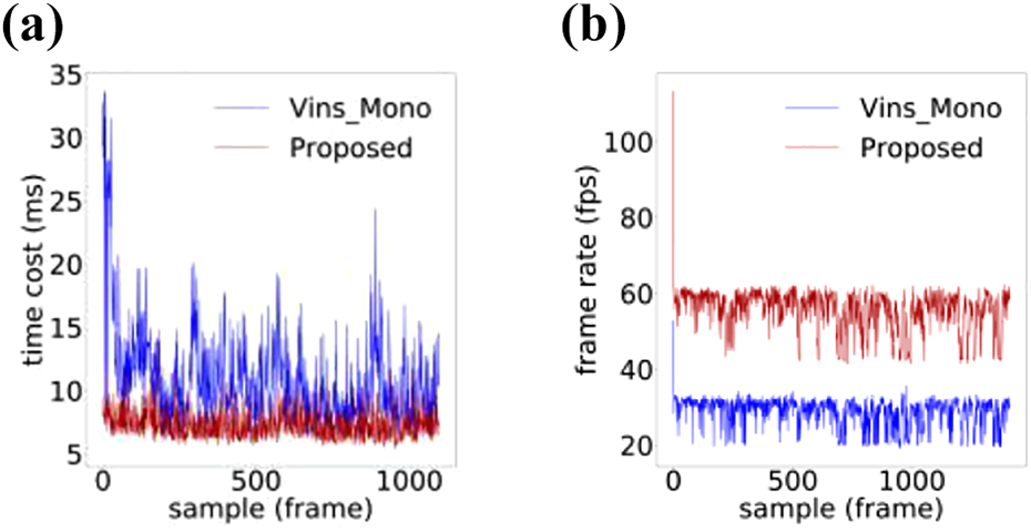
Figures 8 to 15 present the running speed comparison of the proposed scheme and VINS-Mono in terms of marginalization and optical flow tracking. When 10 frames of data are collected in each sliding window, and at most 150 feature points are sampled on an image, it can be seen that the proposed scheme exhibited both fast marginalization and fast optical flow tracking; its marginalization speed was about 1.5–1.7 times faster than that of VINS-Mono, and the optical flow tracking speed was about 1.9 times faster than that of VINS-Mono.

The time cost of (a) marginalization and (b) optical flow tracking on MH_01.

The time cost of (a) marginalization and (b) optical flow tracking on MH_02.

The time cost of (a) marginalization and (b) optical flow tracking on MH_03.

The time cost of (a) marginalization and (b) optical flow tracking on MH_04.

The time cost of (a) marginalization and (b) optical flow tracking on MH_05.
The time cost of (a) marginalization and (b) optical flow tracking on room1.

The time cost of (a) marginalization and (b) optical flow tracking on room3.

The time cost of (a) marginalization and (b) optical flow tracking on room5.
As shown in Figures 8 to 15, the time cost of the marginalization process for VINS-Mono fluctuated more, and sometimes exceeded 50 ms. In contrast, the performance of the proposed scheme was relatively stable during marginalization, and the average time cost was about 9 ms. For the optical flow tracking process, the speed of the proposed scheme was significantly faster than that of VINS-Mono.
For nonlinear optimization, the proposed scheme had the same speed as VINS-Mono. The detailed data are recorded in Tables 2 to 4.
The average time cost of an LM iteration.
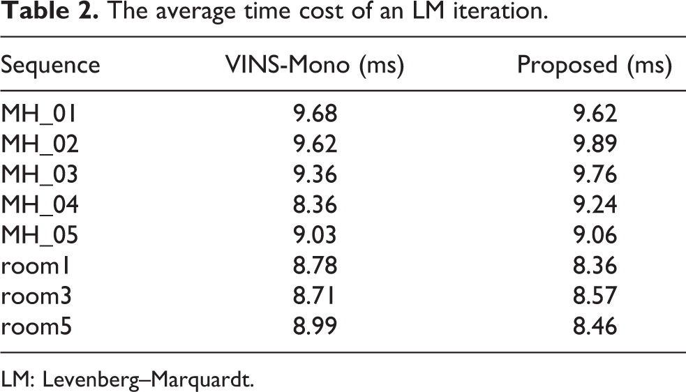
LM: Levenberg–Marquardt.
The average speed of optical flow tracking.

The average time cost of a marginalization.

The proposed algorithm requires data transfer between host memory and GPU memory, thus increasing the time cost. However, this does not cause the running speed of the scheme in this article to be slower than that of VINS-Mono, because transferring data between the host and GPU takes a fraction of the time, and programs run faster on the GPU parallelized than on the CPU. The analysis of the running time of each part of the nonlinear optimization program shows that the construction of incremental equation consumes the most time, and the data transfer between the host and GPU consumes less than 0.5 ms. Constructing incremental equation involves multiple threads writing data to the same memory. For thread safety, atomic functions in CUDA are used, this is why the construction of incremental equations takes much time. The detailed data are recorded in Table 5. However, the proposed back-end optimizer runs on the GPU module of an embedded device, thereby allowing it to make the best use of hardware resources.
Average time cost of each part of an iteration in nonlinear optimization of proposed algorithm (ms).

Experiments show that different sliding window sizes and feature numbers will affect the performance of the algorithm. With the increase of the number of data frames in the sliding window, the running time of both the proposed scheme and VINS-Mono increases gradually. However, when the number of data frames in the sliding window reaches 13, the nonlinear optimization running time of the proposed scheme starts to be less than that of VINC-Mono. This shows that the proposed algorithm can run the program under a large sliding window. Sampling more features in the image will also lead to an increase in the running time of the two algorithms, but the frame rate of the optical flow tracking of proposed algorithm almost does not decrease. This indicates that the number of features that can be selected by the scheme in this article can be larger. The experimental data on MH_05 are recorded in Tables 6 and 7.
Comparison of algorithm performance with different sliding window sizes.
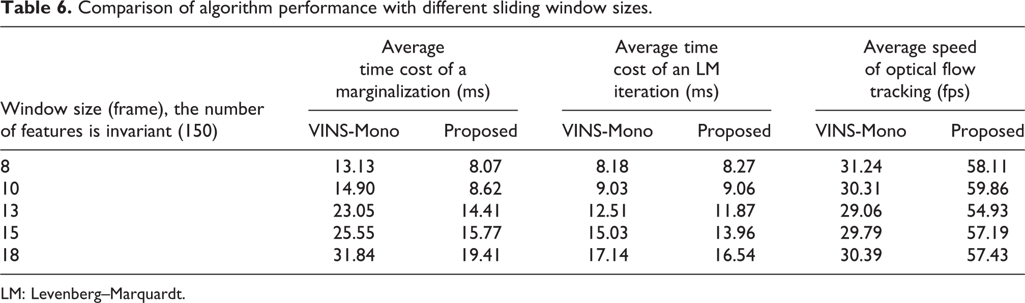
LM: Levenberg–Marquardt.
Comparison of algorithm performance with different number of features.
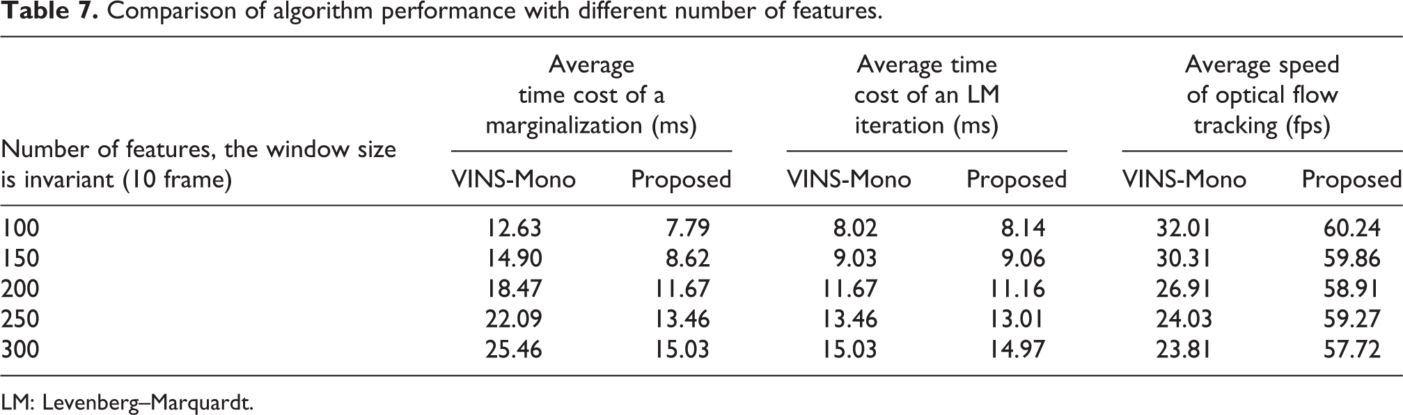
LM: Levenberg–Marquardt.
The accuracies of the proposed scheme and VINS-Mono were also compared. Because the proposed scheme is only the parallel implementation of VINS-Mono and does not involve the change of the mathematical principle of VINS-Mono, there was no significant difference between their accuracies. Figures 16 to 19 show the comparison between the accuracies of the proposed scheme and VINS-Mono on four sequences, namely MH_01, MH_03, MH_05, and room3. The absolute trajectory errors of the algorithm is recorded in Table 8, including root mean square errors, mean value of errors, and maximum value of errors. VINS-Mono uses Ceres for nonlinear optimization. To implement the parallel nonlinear optimization algorithm and enable it to run on the GPU, a back-end optimization program was written. Library namely cuSOLVER in CUDA is used in the program code of the proposed algorithm to solve the incremental equation in nonlinear optimization. However, the GPU in embedded devices has poor double-precision floating-point computing capability, so the pursuit of high precision will lead to the loss of real-time performance of the algorithm. In order to ensure the real-time performance of the algorithm, the accuracy of the proposed algorithm is compromised, which resulted in a slight decrease in the algorithm accuracy. However, there was no serious error in the calculation of the trajectory, and the error was within an acceptable range.
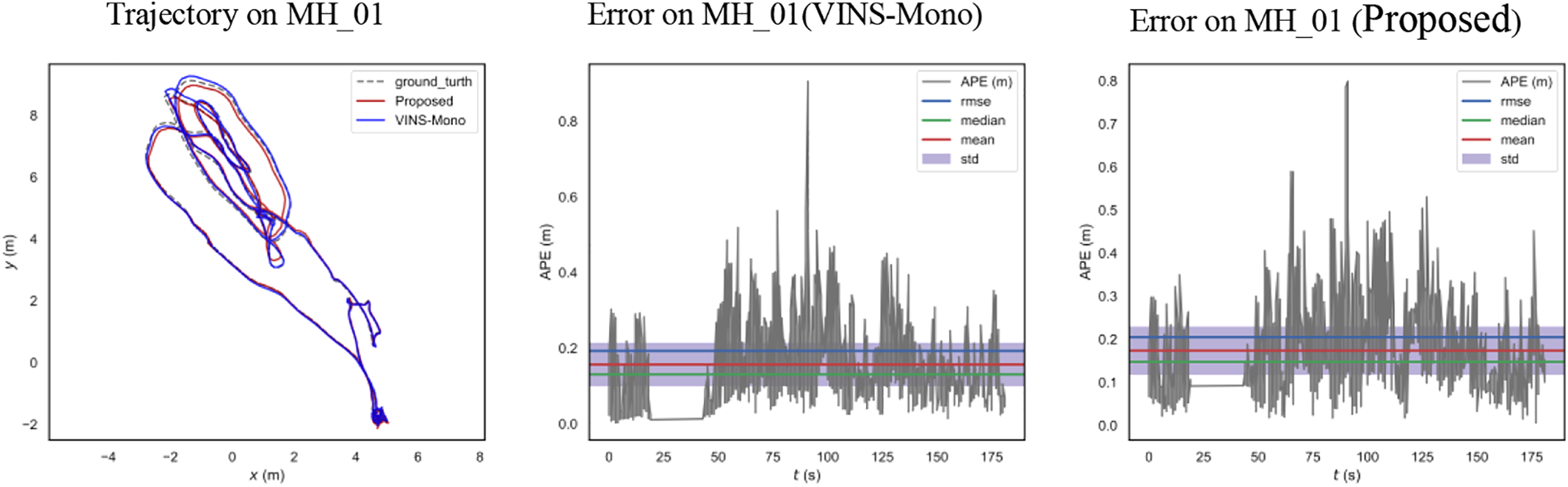
Trajectory and error on MH_01, compared with VINS-Mono.
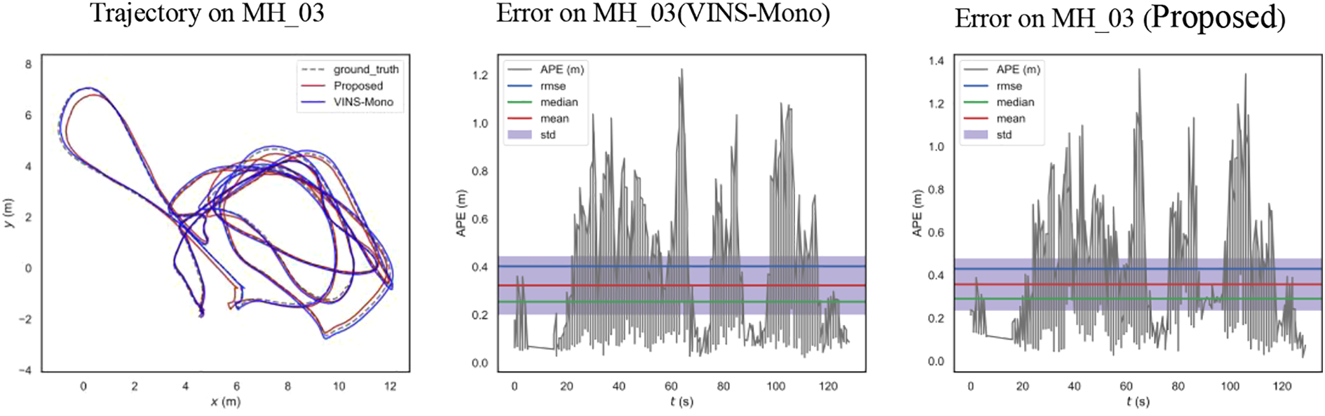
Trajectory and error on MH_03, compared with VINS-Mono.
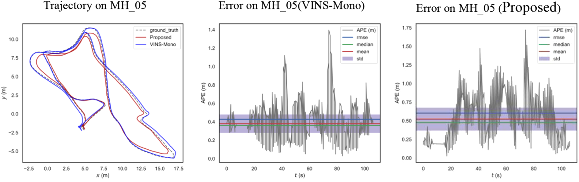
Trajectory and error on MH_05, compared with VINS-Mono.
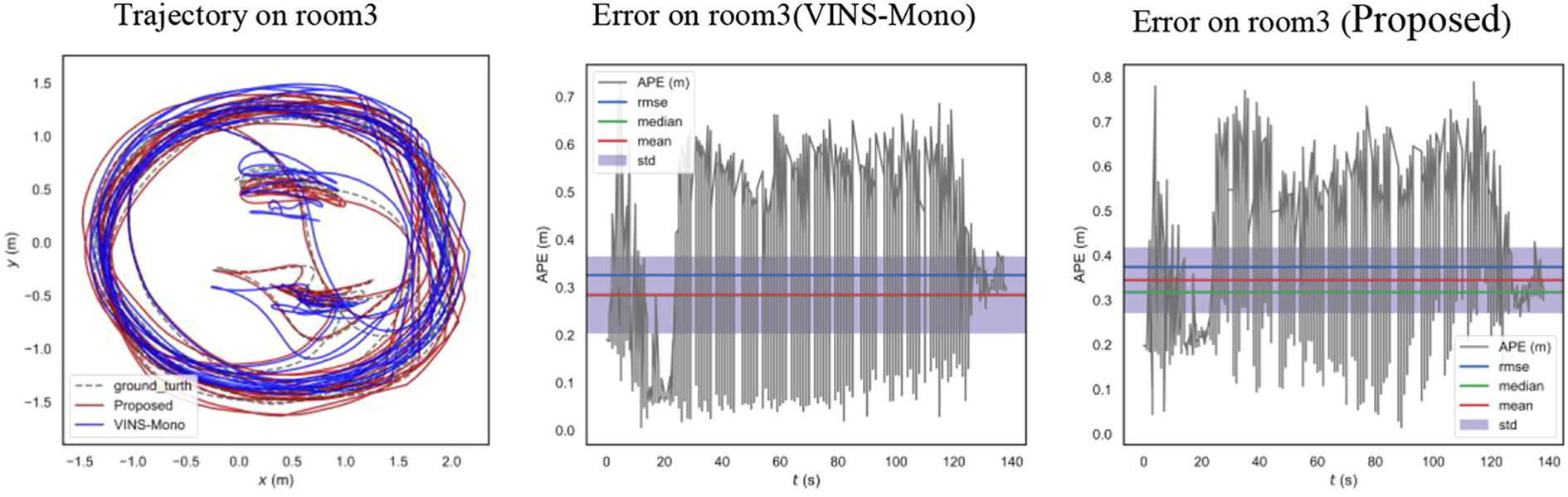
Trajectory and error on room3, compared with VINS-Mono.
Absolute trajectory error.
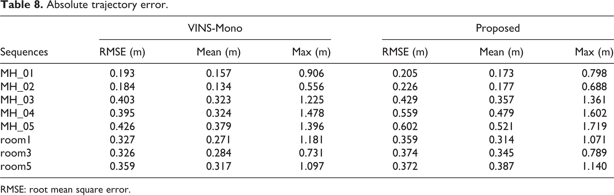
RMSE: root mean square error.
Conclusion
The scheme proposed in this article successfully realizes the parallelization of VINS-Mono and transplants its nonlinear optimization program, optical flow tracking program, and marginalization program to a GPU for execution. The results of experiments conducted in this study revealed that the proposed scheme exhibited better speed performance than VINS-Mono; its optical flow tracking speed was about 1.9 times faster than that of VINS-Mono, and its marginalization speed was about 1.5–1.7 times faster. In addition, because above modules are migrated to GPU in this scheme, the CPU computing burden of embedded devices is reduced, so that they can spare time to complete other main computing tasks without being occupied by SLAM algorithm. At the same time, this scheme avoids the idle GPU on embedded devices when intelligent devices such as UAV use embedded devices with GPU module as computing hardware, the algorithm in this article can make GPU reasonably applied and the hardware resource allocation of devices more reasonable. VINS-Mono implemented the nonlinear optimization algorithm based on Ceres, and compared with it, the optimization algorithm implemented in this article achieved a slightly lower precision, it did not cause serious errors in trajectory calculation, and the error was within an acceptable range. For intelligent devices that use embedded devices with GPUs as computing hardware, such as robots and UAVs, the proposed algorithm can allow for the more reasonable application of the GPUs and hardware resource allocation.
Footnotes
Declaration of conflicting interests
The author(s) declared no potential conflicts of interest with respect to the research, authorship, and/or publication of this article.
Funding
The author(s) disclosed receipt of the following financial support for the research, authorship, and/or publication of this article: This work was supported in part by the National Natural Science Foundation (NNSF) of China under Grant 61863002.