As robots are starting to become part of our daily lives, they must be able to cooperate in a natural and efficient manner with humans to be socially accepted. Human-like morphology and motion are often considered key features for intuitive human–robot interactions because they allow human peers to easily predict the final intention of a robotic movement. Here, we present a novel motion planning algorithm, the Human-like Upper-limb Motion Planner, for the upper limb of anthropomorphic robots, that generates collision-free trajectories with human-like characteristics. Mainly inspired from established theories of human motor control, the planning process takes into account a task-dependent hierarchy of spatial and postural constraints modelled as cost functions. For experimental validation, we generate arm-hand trajectories in a series of tasks including simple point-to-point reaching movements and sequential object-manipulation paradigms. Being a major contribution to the current literature, specific focus is on the kinematics of naturalistic arm movements during the avoidance of obstacles. To evaluate human-likeness, we observe kinematic regularities and adopt smoothness measures that are applied in human motor control studies to distinguish between well-coordinated and impaired movements. The results of this study show that the proposed algorithm is capable of planning arm-hand movements with human-like kinematic features at a computational cost that allows fluent and efficient human–robot interactions.
Recently, there has been an increasing interest in developing robots capable of working jointly with humans on shared tasks. It has been argued that human–robot collaboration is facilitated if robots can maintain an anthropomorphic appearance and can exhibit movements with human-like features.1–3 These characteristics are in support of a natural human–robot interaction (HRI) because they allow human companions to easily interpret the final goal of a robotic movement. In general, predicting the motor intentions of others while watching their ongoing actions is considered a fundamental building block for a successful and fluent human joint action.4 A prominent hypothesis about the underlying processing mechanism postulates the existence of a matching system in the human brain that automatically maps an observed movement onto its corresponding representation in the observer’s motor system.5,6 In joint action tasks, the consequent motor simulation of an action allows the observer to timely select an adequate complementary behavior.7,8 There is a growing body of experimental evidence suggesting that robot motion can activate the action resonance mechanism as well if it shows human-like characteristics.9,10 Since societies and governments are ready to encourage close interactions between humans and artificially intelligent devices,11 the capability of reproducing typical human-like features of motion becomes a necessary requirement for the robots of the future.
So far, most robotics implementations of human-like motion features were restricted to the end-effector motion in relatively simple point-to-point or planar movement paradigms.12 Concerning human upper-limb movements, remarkably robust regularities have been identified that are not in any way implied by the task. A well-established example is the relationship between the geometrical properties of the motion path and movement speed. Point-to-point movements typically reveal roughly straight hand trajectories with a single-peaked, bell-shaped velocity profile.13 Concerning planar curvilinear hand trajectories, a relationship between the angular speed and the radius of the curvature has been described which is known as the two-thirds power law.14 Crucially, humans seem to be highly sensitive to these regularities, exhibiting difficulties in tracking and predicting motion with nonbiological velocity profiles.15,16 Indeed, several studies in the robotics domain have shown the benefits of robotic motion with human-like features for optimizing human–robot collaboration,17 for example, used an object transfer task to directly compare a bell-shaped velocity profile of the end effector (in accordance with a minimum jerk principle) and a typical robotic velocity profile of trapezoidal shape. With a biological profile, the authors report a significantly reduced reaction time of the human receiver due to a better predictability of the movement endpoints. The benefits of biological robotic motion have been also shown in human–robot physical interacting tasks like the joint manipulation of an object. Biological patterns significantly reduce the effort of coordination since the user can follow the robotic motion more intuitively.18 In a more recent study, Maurice et al.19 measured the forces of interaction in a joint movement paradigm in which a robot exhibited either a velocity profile consistent with the two-thirds power law or a nonbiological pattern. It was shown that users were able to decrease in the nonbiological case the forces applied with extensive practice and feedback but never reached forces below those obtained with the natural movement following the two-thirds power law.
In this article, we present a novel Human-like Upper-limb Motion Planner (HUMP) for the generation of human-like collision-free robotic movements, which is deeply inspired from validated models of human motor control. Considering theories on human upper-limb manipulation, the HUMP is formulated as a global planning method that, compared to existing global approaches to human-like robot motion, offers several advantages even in environments cluttered with obstacles.
Inspired from the posture-based motion planning model,20,21 the redundancy of an anthropomorphic arm is solved by firstly selecting a target posture (TP) that places the end effector onto its given target pose and, then, generating a human-like collisions-free trajectory toward it. The planning process takes into account a task-dependent hierarchy of spatial and postural constraints modelled as cost functions. In a typical HRI task, the selection of the grasp posture should, for instance, depend on whether the robot intends to hand over an object to the human partner or to place it elsewhere.7,8 A human-like obstacle avoidance mechanism, which is based on the selection of bounce or via postures, is also adapted for the robotics domain to achieve naturalistic collisions-free trajectories as the superimposition of two movements: a direct movement, from a start to a TP, and a back-and-forth movement, from the start posture (SP) to a bounce posture (BP) and back.20,21 Additionally, the HUMP implements a biological time parametrization of a planned human-like joints-space path in accordance with the Fitts’ Law, which finds vast empirical verification in human reaching and grasping.20,22
The proposed HUMP is also designed to mimic the kinematic characteristics that a human hand exhibits during the manipulation of an object in pick-and-place tasks.23,24 In specific, high levels of accuracy provoke more accentuated phases of motion for approaching a hand target pose and retreating from it.23 Mimicking human phases of motion offers a more flexible modulation of a movement, which can also show more veridical human-like kinematic features during manipulation.
To quantitatively evaluate the human-likeness of the generated trajectories, we use measures that have been used in clinical studies in humans, namely: the Normalized Jerk Score (NJS) and the Number of Movement Units (NMU). These simple indexes have been used to discriminate between normal and impaired goal-directed movements.25,26 Results show that HUMP can be used for planning collisions-free naturalistic movements with a relatively small computational cost that allows a fluent HRI.
The remainder of this article is organized as follows. The second section provides an overview of the most recent techniques of human-like arm motion planning that have been also applied for obstacles-avoidance, while, in the third section, the anthropomorphic robotic platform that has been used for experimentation is briefly described. The fourth section describes the features of human motor control that are transferred into the HUMP with the purpose of generating human-like collisions-free movements. The fifth section presents how the proposed method implements trajectory generation in sequences that compose a movement with the objective of mimicking human arm movement segmentation. The main HUMP algorithm is also presented here. The sixth section presents details concerning the implementation of the HUMP algorithm and the adopted experimental setting. In the seventh section, the measures for validating the human-likeness of arm motion in our tests are presented in more detail. The eighth section presents different experimental settings adopted from our previous work on a cognitive control architecture designed for natural HRI and the corresponding results. A kinematical analysis of the proposed human-like obstacle avoidance mechanism is also here described on settings that have been addressed in a similar study with humans. The article ends in the ninth section with a discussion on the obtained results and on the future investigations.
Related work
The avoidance of obstacles in human-like arm motion generation has been poorly addressed, although it is of crucial importance in human-centered robotics. Most of the proposed techniques are global, rely on customized sampling-based planners, and often ignore typical human-like time parametrizations.12 In global planning methods, like the proposed HUMP, collisions-free trajectories are generated before the beginning of a movement (off-line) by only considering sensory information coming from the workspace of a robot. Global methods (such as the sampling-based methods) also allow to integrate specific cost functions, which can be derived empirically from human motion data to generate movements with human-like peculiarities. For instance, Zacharias et al.27 proposed to find human-like goal configurations for a robotic arm using an ergonomics research criterion called Rapid Upper Limb Assessment (RULA). Given a specific planning problem, the start and goal postures of the arm were obtained by a RULA-driven inverse kinematics (IK). Then, the trajectory to transport the arm from its start to its goal posture was generated by using the bidirectional RRT (Bi-RRT) algorithm.28 Its sampling routing was adapted with a database of configurations having RULA scores in a human-like range of values. Tests showed that the RULA-based sampling routine could generate smooth and human-like arm paths. However, since the focus of the planning process is on the spatial path and the time parametrization is neglected, a robot motion may exhibit unrealistic and non-human-like velocities.
The Bi-RRT algorithm was also used by Xie et al.29 for the generation of natural reaching movements through a narrow passage. The authors hypothesized the existence of a human-like Target Arm Pose (TAP), which can be obtained from mimicking human arm postures at given goal hand poses. Combined with the TAP, the Bi-RRT algorithm was applied to plan collisions-free reaching movements for a seven-degree of freedom (DOF) robotic arm, which was required to go through a narrow passage. The proposed hypothesis was also successfully tested in obstacles-free environments, showing the capability of generating smooth end-effector paths. However, human-like velocity profiles are not considered and the proposed algorithm may suffer of poor generalization, since the TAPs are arbitrarily selected for the specific needs of a task.
The First-order Retraction RRT (FR-RRT) algorithm30 was used by Xie and Zhao31 to generate collision-free trajectories for a four-DOF robotic manipulator. Here, the authors presented a method to plan handing-over movements during HRIs under the consideration of a given target position for the passage of an object. The proposed approach required a first investigation concerning optimal hand-over target positions and corresponding arm postures. Then, a motion planning scheme, which is based on the minimum jerk of the hand path,14 was presented in an obstacles-free environment. The trajectories of the joints were controlled by the gradient projection method,32 which took into consideration the total arm potential energy as a measure of performance. Based on the observations of the human motor behavior, the generation of collisions-free arm trajectories was driven by hand via-points, which were selected in the obstacles-free portion of the workspace. In this case, the minimum jerk hand path was tracked by the application of the FR-RRT algorithm.30 Tests demonstrated that the proposed method can efficiently solve the redundancy problem of the arm without involving any IK. However, the planner may lack of generalization to different tasks because, for instance, obstacles-avoidance is biased by the selection of arbitrary hand via-points.
More recent techniques that also addressed the obstacles-avoidance problem take inspiration from captured regularities of human arm motion in the accomplishment of selected tasks.33,34 For instance, Liu et al.33 presented an analytical IK resolution of a seven-DOF arm that maps postures by positioning arm key points recorded from human reaching motion. The proposed algorithm maintains the wrist and the elbow in line with the palm/end effector and iteratively adjusts a mapped configurations to respect physical joints-space limitations. Simulations demonstrated the capability of the proposed IK algorithm of minimizing the distance with the recorded swivel angle values even during the avoidance of a spherical-like obstacle.
An inverse dynamics controller was proposed by Lauretti et al.34 to enhance the functional anthropomorphism of redundant manipulators in reaching and pouring tasks. In particular, the parameters of Cartesian- and joints-space dynamical movement primitives35 are trained starting from demonstrations of captured human arm motion and, then, a hybrid approach is formulated by coupling these two dynamics in the null-space of the Jacobian. Obstacles-avoidance terms are added in both the Cartesian and the joint primitives such that the distances between the center of an obstacle and key points of a seven-DOF manipulator are maximized. Experiments showed the capability of the proposed hybrid technique of maximizing the similarities with human arm postures and of selectively avoiding collisions with obstacles that might be encountered along the path.
Compared to the most recent solutions of human-like arm motion generation, the proposed HUMP offers a comprehensive framework for planning simple reaching and complex picking and placing movements with spatial and temporal human-like features. Importantly, the HUMP is the first planner that addresses the avoidance of obstacles in a human-like manner, which is validated in experimental paradigms of human obstacles-avoidance. Moreover, a consistent degree of generalization is promoted because the proposed mechanism is not limited to certain categories of obstacles, does not assume given task-related via postures, and does not depend on any captured human motion data. The level of human-likeness that features the planned motion is quantitatively and qualitatively assessed and ensures a limited computational cost for a fluent HRI (c.f. the eighth section).
The robot ARoS
To illustrate the basic assumptions and technical details of the proposed planner with a concrete example, we refer in the following sections to the robotic platform—an Anthropomorphic Robotic System (ARoS shown in Figure 1(a))—used for the experimental evaluation in the object manipulation tasks.36
ARoS (a) is equipped with a seven-DOF robotic arm (b) and a three-fingered Barret Hand (c). The robotic arm-hand system is illustrated with the given dimensional parameters, joint angles and most relevant points of interest (e.g., the Hand point). ARoS: Anthropomorphic Robotic System; DOF: degree of freedom.
This platform, designed and built at the University of Minho, consists of a static torso, equipped with a seven-DOF anthropomorphic robotic arm (shoulder: three DOFs; elbow: 1 DOF; wrist: 3 DOFs), a three-fingered Barrett hand and a stereo vision system mounted on a pan-tilt unit. The dimensions of the torso were determined taking into account anthropometry studies.37Figure 1(b) shows the robotic arm and Figure 1(c) shows the Barrett hand mounted as end effector with the corresponding joints. For the postural representations, we apply the Denavit–Hartenberg (D-H) convention.38 To describe the posture of the upper limb, the following notation is used
where represents the arm posture with n joints
and represents the hand posture with m joints
In our case study with the robot ARoS, and , therefore we obtain the following equations
The HUMP: Concepts and theoretical framework
The main concepts of the HUMP take inspiration from the posture-based motion planning model of human motor behavior, as presented in the first section, but there are also aspects that have been adapted for the robotics domain. Specifically, a TP is not selected by considering a group of candidates,20 but it is chosen to minimize the angular jerk (third time derivative of position) of a direct movement. Similarly, a BP is selected to minimize the angular jerk of a back-and-forth movement, which is reformulated to offer a more flexible tuning of a collisions-free trajectory and respect required boundary conditions. Since human manipulation that demands high endpoint precision is managed with separated phases of motion,39 the proposed method also plans a movement through independent and interconnected phases for a convenient management of the approach and the retreat actions in delicate areas of interest. For this reason, we take inspiration from the results obtained by Milner23 and Burdet and Milner,24 which exhibited distinct human hand kinematical phases during accurate manipulation. Particularly, the HUMP proposes the formulation and the composition of different (sub)movements, which are designed to mimic these findings on human accurate manipulation during approaching and retreating phases.
Next, we present the basic concepts and the theoretical framework used for generating human-like collisions-free arm-hand movements for humanoid robots. The extension to sequences of (sub)movements is addressed in the fifth section. As mentioned, the planning process starts with the selection of an optimal TP. It takes into account the SP of the arm and the hand (from the manipulator and the Barrett Hand of ARoS), the information about the type, position, orientation of the objects in the workspace (from the vision system of ARoS), the information about a given object, target of manipulation, and an appropriate grasping behavior (from our cognitive model8). Subsequently, for each joint, its trajectory (time history of position, velocity, and acceleration) from the SP to the TP is computed. This joints-space trajectory defines a direct movement. Then, the system searches for a feasible collisions-free movement, which is based on the selection of a suitable BP. This BP serves as a subgoal for a back-and-forth movement, which is superimposed on the direct movement. The TP that is finally reached is the same as for the direct movement, only the selected path differs to guarantee the avoidance of collisions (Figure 2). Importantly, in the selection procedure of the target and the BPs, the planning takes into account anatomical constraints and obstacles-avoidance for the entire duration of a movement. Thus, when these postures are found, a planned upper-limb movement is always anatomically feasible. The details concerning the resolution of the redundancy problem under precise task requirements are given in sections “TP selection” and “HTP selection.”
A direct movement from the start to a target posture (a) and a composite movement, which is the superimposition of a direct and a back-and-forth movement (b). A back-and-forth movement is a movement from the start to a bounce posture and back (b), which is selected to obtain a collisions-free composite movement. Kinematics of a joint during a movement (c).
TP selection
An optimal TP, , at , where T is the movement duration (the computation of movement duration or movement time is discussed in section “Human-like time parametrization”), is a posture that minimizes the displacements of the joints from the SP to the TP, taking into account obstacles-avoidance, physical joints limits, and a desired grip type at the end of the movement (e.g. the grip at the moment of grasping an object).
The TP selection process for the robotic arm and hand can be divided into the selection of a set of finger joints and a set of arm joints. Hence, we denote the TP by
where and are vectors with the values to be specified for the angular joint positions of the arm and of the fingers in the hand, respectively. We start by computing the hand target posture (HTP), , then we proceed with the computation of the arm target posture (ATP), .
HTP selection
The HTP, , depends on the specific hardware of the robotic hand and on the type of movement to be generated (c.f. the fifth section). For example, it can be a set of angular joint positions for a hand pointing gesture or a specific grasp configuration to grab an object with a desired grip type (e.g. precision or power grip as shown by Napier40). For our case study with ARoS that is equipped with a three-fingered Barrett Hand, the selection of a HTP is described in our previous work by Costa e Silva et al.41 Next, we proceed with the computation of the ATP, .
ATP selection
An optimal ATP, at , is a posture that satisfies the following constraints:
(co1) allows an object to be successfully grasped or manipulated,
(co2) avoids collisions between the arm-hand and the obstacles in the workspace and with the body of the robot,
(co3) respects the physical joints limits and
(co4) minimizes the cost associated with moving the arm from the Arm Start Posture (ASP), (at ), to the ATP, (at ), following a minimum angular jerk trajectory.
The minimum jerk criterion has been typically applied to model human-like hand motion in Cartesian space.14 However, we apply it in the joints space. Motivation for this is that the minimum angular jerk criterion has been proposed as a model to explain simultaneously the slightly curved paths and the bell-shaped hand velocity profiles that are consistently observed in human upper-limb movements.20,42 The cost associated with moving the arm from the ASP, , to an ATP, , following a minimum angular jerk trajectory is
where the nonnegative parameters are joint expense factors, which permit not only that the joints contribute differently to the selection of the ATP but also to the trajectory selection (c.f. section “Trajectory selection”), providing a degree of generalization of the planned movements. The introduction of joint expense factors is motivated by the fact that, in humans, the arm joints may have different cost factors, therefore the relative importance of the various joints for the selection of the ATP may vary, depending, for instance, on personal preferences.20
The ATP is selected as the optimal solution of the following nonlinearly constrained optimization problem, taking equation (7) as a cost function
Here:
constraints (9) impose a determined relationship between the hand pose (obtained through direct kinematics from the angular joint positions of the arm and hand ) and the target pose, , which is a seven-dimensional vector representing the target position , and orientation (i.e. the parameters of the quaternion) of the local frame , and is a vector of allowed tolerances in positioning and orienting the end effector at the given target;
constraints (10) guarantee obstacles-avoidance at the TP, where is a clearance distance from the obstacles and
constraints (11) ensure that the selected ATP, , satisfies the physical joints limits, where represent the lower and the upper joints-space limits of the arm, respectively.
The vector functions and , in (9) and (10), respectively, are nonlinear functions of the TP. They are defined using the direct kinematics that map the space of the joints to the Cartesian space. This mapping is well-defined for any robotic arm and uses only the D-H parameters of the robot. A detailed formulation of these functions is described in our previous work by Costa e Silva et al.41
Solving the optimization problems (8)–(11) means solving the IK problem of a redundant manipulator while a given cost function is minimized in the joints space. Running an interior-point method to achieve a minimum (c.f. the sixth section) permits to overcome typical issues of convergence failures related to the application of a Newton-method search for numerical IK.43
Trajectory selection
Once a TP has been found, the trajectory (time history of position, velocity, and acceleration) from the SP to the TP is computed.
The direct movement
The trajectory that brings the arm and the hand from their SP to their TP is defined by
where is the direct movement. Its specific formulation depends on the type of movement phase—transport, approach, retreat—to be generated (c.f. the fifth section), but it is always defined so that (i) it generates a hand velocity profile that is consistent with observations in human arm movements;20,23 (ii) guarantees boundary conditions on position, velocity, and acceleration; and (iii) the joint angles are within their mechanical limits during the entire movement duration.
Collisions-avoidance: The back-and-forth movement
Using equation (12) and the forward kinematics of the arm-hand, it is possible to predict collisions with the obstacles in the environment, the body of the robot, and the object to be grasped (in case of manipulation). To ensure the avoidance of collisions, a feasible movement, that still brings the arm-hand from the SP to a previously selected optimal TP, needs to be computed. For this purpose, we use the notion of BP, which was firstly introduced concerning planar movements44,45 and, later, in relation with movements in a three-dimensional space.21 A feasible movement is found by computing an optimal BP, that is, a posture that serves as a subgoal, for a back-and-forth movement and minimizes the angular displacement over its duration. This movement consists of first moving the arm and the hand from their SP, , to a BP, , (forth) and next moving back to the SP again (back). The back-and-forth movement is superimposed on the direct movement and it is intended to avoid collisions with obstacles during the entire execution of the (composite) movement (equation (13)). As a result of the superimposition in equation (13), trajectories change but the TP that is reached remains the same (Figure 2)
The back-and-forth movement, , is proposed as formulated by equation (14)
where is the normalized time, being T the movement duration. In equation (14), , with is the parameter used to control when the BP, , is reached. The motivation for using a squared sinus function for the back-and-forth movement is primarily based on the fact that discrete movements that start and end in a standstill, can, in principle, be considered half a period of a cyclical movement.46 Although the posture-based motion planning model has mainly inspired this work, the proposed formulation in equation (14) substantially differs from the formulations given by Vaughan et al.21 for a better integration into the robotics domain. In specific, the back-and-forth movement in equation (14) provides one more degree of adaptation through the parameter tb and, importantly, ensures null boundary conditions in position, velocity, and acceleration so that at only the direct contribution emerges. The sinusoidal element remains a key in the moment that the directional reversal occurs, while the zero velocity crossing remains a key at the start and at the end of the movement. The kinematic profile adopted here thus capitalizes on core kinematic features of both discrete and cyclical motion. Furthermore, the squared sine function is also continuously differentiable, which is an important feature when we use deterministic optimization methods that require such smooth functions.
We set , so that the “forth” and the “back” phases take 50% of the total movement time, respectively. The underlying assumption is that the impact of the obstacles on the movement trajectory will be evenly distributed across the entire movement. Empirical evidence of this hypothesis has been reported by Vaughan et al.47 It is worthwhile noting that the model does not presume that the location of a supposed collision is at 50% of the straight-line distance between the start and the end of a movement, nor does it presume that it is halfway in terms of movement time. In contrast, the location can be anywhere in the workspace, because the BP, , is selected taking into account that no collision occurs for the entire duration of the composite movement given by equation (13). This is explained next.
BP selection
Similarly to the ATP selection procedure, the aim is to select an optimal BP, , where n and m are the number of DOFs of the arm and of the hand, respectively. In fact, the BP to be selected, , is a composition of the arm bounce posture(ABP), , and of the hand bounce posture(HBP), as described in equation (15)
The BP minimizes the jerk of the back-and-forth movement in equation (14) subject to the following constraints:
(co1) collisions-avoidance, over the entire duration of the composite movement, with any obstacle in the workspace, with the body of the robot, and, eventually, with the object that has to be manipulated;
(co2) the mechanical joint limits are respected over the entire duration of the composite movement;
(co3) minimization of the cost function
that is associated with the displacement of the joints of the arm and of the hand from their SP, , to their BP, .
To formulate this selection problem, we take into consideration the entire trajectory of the composite movement, in equation (13) and we discretize the time into equally spaced steps denoted as , where is the step size and (more details are given in section “Human-like time parametrization”). Consequently, the convention adopted is that represents the configuration of the joints at time step ti during the trajectory. We formalize these concepts as a nonlinearly constrained optimization problem as follows
where are the vectors with the lower and the upper mechanical joint limits, respectively, hb is a vector of nonlinear functions defined to guarantee the avoidance of collisions, being a vector of positive clearance distances at time ti. For every instant ti, constraints (18) guarantee that the trajectory of the joints does not overcome their physical limits; inequalities (19) ensure that there is not any collision with (i) the object to grasp (only in picking), (ii) the obstacles in the scenario, and (iii) the body of the robot; constraints (20) ensure that the selected BP is within its physical limits. The specific formulation of the constraints (19) is described in our previous work by Costa e Silva et al.41
The HUMP: Trajectory generation in sequential phases of a movement
Classification and segmentation of a movement
Typical object manipulation tasks can be segmented into meaningful action phases in which an object is approached, grasped, lifted off a surface, moved, and placed on a surface again. The transition between the different phases is defined by distinct sensory events like making or breaking contact between the manipulator and an object or between an object and a surface. These events define subgoals of a task.39 The division in functional units or primitives of goal-directed motor acts supports a flexible task planning since the primitives represent elementary building blocks, which can be combined and adapted in many different ways to generate complex goal-directed behaviors (for robotics examples, see Stulp et al.48). In the proposed planning system, a temporal task segmentation implies that the TP of a certain motor act (e.g. picking) becomes the SP of the subsequent motor primitive (e.g. lifting).
A segmentation in different motor primitives has been also proposed for the kinematics level to explain observed regularities in human motion. During reach-to-grasp movements, the wrist velocity typically shows a single-peaked, bell-shaped profile, with the acceleration phase lasting shorter than the deceleration phase. This asymmetry tends to become more prominent for movements requiring higher precision, leading to a nearly constant velocity when the arm approaches the target position. As shown by Milner,23 this finding can be well explained by the superimposition of sub-movements generated at discrete time intervals. The sub-movements are assumed to share the same basic velocity profile of the initial hand transport into the vicinity of the target but could be scaled in time and magnitude to blend together as motor skills develop (Figure 3). To account in the proposed HUMP for the impact of precision constraints on the limb velocity profile, we further segment a picking movement, and also a placing movement, into an initial transport phase followed by an approach phase. This segmentation also captures well the biphasic nature of the grasping component of typical human prehension, which appears to be temporally coupled with the reaching component.49 During hand movements, there is first a progressive opening of the grip up to a maximum grip aperture which is proportional to the size of the object. This is followed by a gradual closure of the grip until it matches the size of the object. The maximum grip aperture occurs at about two-thirds of the way through the duration of the reaching, which roughly coincides with the start of the approach phase.
Wrist tangential velocity (bold) and underlying sub-movements (dotted) obtained by decomposition of human arm movements to place cylinders of different sizes.23 After a bell-shaped peak, a quasi-constant velocity phase features the conclusion of a hand movement when accuracy in manipulation is required.
Figure 4 illustrates the temporal segmentation of a pick-and-place task in the different phases of an upper-limb movement with the labels that we use. Grasp (g) and ungrasp (u) are treated as transitions between the approaching (to pick) and lifting motions, and the approaching (to place) and depart motions, respectively. We use the common label R (for retreat) to describe both the object lifting from the surface and the final depart of the hand from the placing position, since the proposed planner treats both phases equally.
Temporal division of the movements in phases. Pick and place movements are generated when the manipulation of one object is required. Otherwise, a single-phase move movement is planned to transport the end effector from one pose to another one of the reachable workspace.
Pick and place movements consist of a combination of three object-directed primitives transport (T), approach (A), and retreat (R). In addition to the object-directed movements pick and place, the HUMP also generates move movements that do not manipulate any object in the workspace and, therefore, are only composed by a transport phase, which transports the hand toward its target pose and brings the fingers toward their desired posture.
The transport, approach, and retreat phases are also distinguished by a selection of a specific TP as it is described in section “TP selection.” Next, we present how these phases are generated, taking into account the type of movement (pick, place, or move) to which they belong.
Transport phase
The transport TP is a posture , where is the ATP and is the HTP. is selected as explained in section “ATP selection” for a given transport hand target pose. Next, the selection of the HTP and the composition of the trajectory in the Transport phase are described.
Transport HTP selection
In pick movements, the transport HTP is calculated as described in our previous work by Costa e Silva et al.41 However, if an approach phase follows, the values of are modified to obtain a slight greater aperture of the fingers than it is necessary. This is done to mimic prehension and guarantee a successful grasping transition.
In place movements, the transport HTP is constrained by the fact that the object that is being manipulated has to remain held by the end effector. Therefore, we set the transport HTP equal to the Hand Start Posture (HSP), that is, . Move movements are only featured by a hand transport phase, which is not directed toward objects. Hence, in this particular situation, the joint angle values in can be set arbitrarily.
Transport direct movement
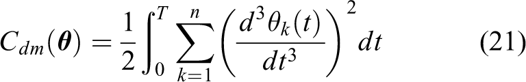
For the transport phase, the direct movement consists of a trajectory that is generated based on the minimum angular jerk principle. With this approach, the end-effector trajectories (in extrinsic spatial coordinates) with a bell-shaped velocity profile do not need to be modelled explicitly, in contrast to other approaches, but rather emerge from the joint displacements.42 The direct movement is computed by minimizing the jerk over the all movement duration
where n is the number of joints, is the joint angle position at instant t, and T is the movement duration. This is a typical variational problem and the solution is a fifth-order polynomial whose coefficients may be determined applying boundary conditions on position, velocity, and acceleration. The solution is the transport direct movement
where is the vector with the start joint angles (at ), is the vector with the target joint angles (at ), and is the normalized movement time. and are the start and the target joint velocities, respectively, and and are the start the target joint accelerations, respectively. Equation (22) guarantees that the joint angles are within their mechanical limits during the entire movement duration because (i) the values of the transport TP are into their admissible range and (ii) equation (22) is also a monotonic increasing or decreasing function that generates values from to for each kth joint. Therefore, since both the SP and the TP obey the constraints limits of the joints, the same happens in any step of the trajectory. Velocity and acceleration can be obtained deriving equation (22) over time. The movement of the joints follows a straight-line path in the joints space with a bell-shaped unimodal velocity profile. In the task space, this may result in a straight path or in a slightly curved path, both with bell-shaped velocity profile, which is consistent with observations in human arm movements.20 By this method, we do not need to model explicitly the bell-shaped velocity profile of the end effector, but it rather emerges from the displacements of the joints (c.f. the eighth section).
Transport back-and-forth movement
The second component of the transport phase consists in the back-and-forth movement that is given by equation (14), and it is intended to avoid collisions (during the entire execution of the transport phase) with the obstacles in the workspace, the body of the robot, and, in case of pick movements, also with the object to grasp. Next, we outline the BP selection process, described in section “BP selection,” to specify the constraints of the optimization problem (17)–(20) according to the type of movement.
In move movements (composed only by a transport phase), the HBP, , is completely selected by the solution of the optimization problem given by (17)–(20). During the transport phase, in place movements, the object that is being manipulated is held by the hand for the entire duration of the phase. Therefore, in this case, we set (at ). This implies a null contribution of the back-and-forth movement concerning the total motion of the fingers in equation (13). In pick movements, likewise for the HTP selection (see section “HTP selection”), the selection of depends on the specific hardware of the robotic hand. In the three-fingered Barret Hand, the middle finger is always opposite to the other two fingers, thus and we can also control the position of the fingers with one variable, that is, . This variable is then selected by the solution of the problem (17)–(20) (see Costa e Silva et al.41 for details).
The solution of the optimization problem (17)–(20) is a BP, , which gives the back-and-forth component of the transport phase trajectory (equation (14)).
Composite movement of the transport phase
In the transport phase, the trajectory of each joint is obtained by the superimposition of the back-and-forth movement onto the transport direct movement
where and are given by equation (22) and equation (14), respectively. Equation (23) guarantees a feasible and human-like collisions-free trajectory with continuous angular velocity and acceleration. Joint limits are not violated and, by setting the movement time T () appropriately, the maximum allowed angular velocity and the maximum joint acceleration of each joint are never reached (see section “Human-like time parametrization”).
Velocity and acceleration over the trajectory, which are obtained deriving equation (23) with respect to time, are given by equations (24) and (25)
Approach phase
Following the transport phase comes the approach phase. The approach TP is a posture , where is the ATP and is the HTP. The selection of is performed as explained in section “ATP selection” for a given approach target hand pose. Next, we explain how to compute the HTP, .
Approach HTP selection
In pick movements, the transport phase transports the hand onto the close proximity of the object to grasp with the adequate preshaping of the fingers. Next, the approach phase brings the hand into the pose of grasping and concludes it. For a successful grasp, the value of joints in the fingers are computed according to the size of the object to grasp, as described in our previous work by Costa e Silva et al.41 In place movements, the transport phase transports the grasped object into the close vicinity of its final location. Then, the approach phase concludes positioning of the object in its goal pose. Thus, the approach HTP remains constant to hold safely the object being placed.
Approach direct movement
The transport phase always brings the hand into close proximity of its goal pose using a feasible and collisions-free trajectory for the arm-hand, because it is reasonable to assume that there are no obstacles in the close vicinity of the target. On the contrary, there might not exist a solution of the planning problem, because the paths toward the goal are critically obstructed. Thus, a direct movement per se is sufficient to generate a collisions-free trajectory for the approach phase.
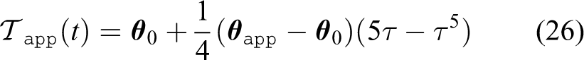
This phase brings the arm and the hand from the TP of the transport phase, , (which is now the SP for the approach phase, ) to the approach TP, . The proposed formulation of the approach direct movement, , aims to mimic the results illustrated in Figure 3 and it is given by
where , , T is the total duration of the approach phase, and is the normalized time. The trajectory of the joints during the approach phase, (equation (26)), is a monotonic increasing, if is positive, or decreasing function, if is negative, that generates values from to for each kth joint. Therefore, since both the SP and the TP are within the admissible range of the joints, the entire approach direct movement respects their physical limits. Equations (27) and (28) model the velocity and the acceleration of the approach phase, respectively. In equation (27), it is possible to note that the arm and the hand stop at the end the approach phase to start the grasp/ungrasp transition. At the beginning of the approach phase, the joints have velocity and acceleration , which are equal to the velocity and acceleration of the transport phase movement in equation (23), respectively. This implementation ensures a correct composition of the transport phase and of the approach phase.
Retreat phase
Following the approach phase, and the grasp/ungrasp transition, comes the retreat phase. The retreat TP is a posture , where is the ATP and is the HTP. The retreat ATP, , selection is performed as explained in section “ATP selection” for a given retreat target hand pose. Next, we explain how to compute the retreat HTP, .
Retreat HTP selection
In pick movements, the HTP for the retreat phase is constrained by the fact that the object is held by the hand. Therefore, we set the retreat HTP equal to the retreat HSP, that is, . For a successful ungrasp in place movements, the values of the retreat HTP are computed as described in our previous work by Costa e Silva et al.41 considering a slightly increased aperture of the fingers with respect to the size of the object previously grasped.
Retreat direct movement
Similarly to the approach phase, the retreat phase is also formed by a direct movement that brings the joints from their target of the approach phase (SP, ) to the current TP, that is, the retreat TP, . In this phase, it is reasonable to assume an obstacles-free region in the close proximity of the current goal, for the same reasons of problem feasibility mentioned in section “Approach direct movement.”
Since the retreat phase is the initial part of a transport phase in the next movement, the proposed formulation replicates the increasing velocity of the joints until the achievement of their TP and it is given by
where , , T is the total duration of the retreat phase, and is the normalized time. The trajectory of the joints in equation (29) is monotonically increasing or decreasing according to the sign of for each kth joint. Since and are within the range of the joints, equation (29) guarantees that the values of the trajectory remain within their physical limits. Equations (30) and (31) model the velocity and the acceleration of the retreat phase, respectively. It is worth noting that the arm and the hand start with zero velocity and acceleration immediately after the grasp/ungrasp transition. The retreat phase ends with velocity and acceleration , which have to be set as start boundary conditions of the transport phase in the subsequent movement. This setting guarantees the correct composition of the retreat phase with the following transport phase.
Human-like time parametrization
As seen, all the movements that are generated by the proposed motion planner are time normalized and time is also discretized. Thus, given the trajectories of each phase in a movement, their duration, T, the number of steps, , and size of each time step, , need to be computed.
Movement time
Rosenbaum et al.20 assumed that for each kth joint there is an optimal movement duration, Tk, that is based on the Fitts’ Law applied to joint angular displacement, .22 For this reason, we propose the following formulation
where is the expense factor of the kth joint, is the number of time steps in the movement, is the maximum allowed angular velocities of the kth joint. The term is added to guarantee that the maximum allowed angular velocity of the kth joint is never reached. Then, since that all the joints start and end their movement synchronously,50 we propose to compute an optimal total duration, T, as the weighted average of the optimal duration for each joint (equation (35))
Number of steps
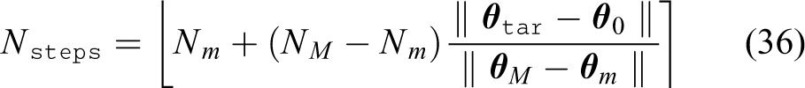
The number of steps, , is proposed to be computed as shown by equation (36) and it is dependent on the distance between a SP, , and a TP, as
where NM and Nm are the acceptable maximum and the minimum number of steps, respectively.
Time step
A first approximation of the correct time step size is given by
which is based on the trajectory with null boundary conditions, that is, the movement starts and ends with zero velocity and acceleration. The obtained time step size, , should provide a trajectory that does not reach the maximum allowed angular velocities, , and the maximum allowed angular accelerations, , but with the settings of the boundary conditions (,,,) in equation (22), this condition might not be respected. Therefore, the time step size, , is increased cyclically of an arbitrarily small value, , if at least one joint achieves a maximum angular velocity greater than or a maximum angular acceleration greater than during its trajectory. However, this is simply a safety check because, for a correct composition of the phases in the planned movements, boundary conditions should be set properly (see sections “Approach direct movement” and “Retreat direct movement”) and, more importantly, should not be set close to their physical limits.
The main algorithm
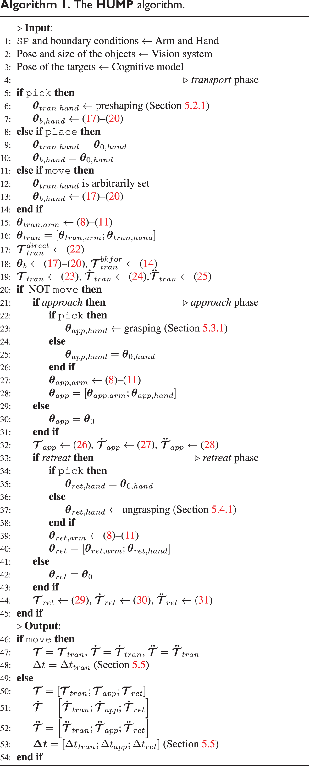
The general implementation of the planner is given by the pseudo-code in Algorithm 1, which shows how a movement (pick, place, or move) is generated. As seen (refer also to Figure 4), a move movement consists of a single movement phase transport (T), while pick and place movements are further composed by a sequence of two movement phases: approach (A) and retreat (R). Thus, the transport phase is always planned for any of the three types of movements, while approach and retreat can only be planned for pick and place movements.
The inputs to the planner are the start position, velocity, and acceleration of the each joint of the arm and of the hand, which are provided by the hardware. The pose and the size of any object in the workspace are also inputs and are provided by the vision system. The size of the body of the robot is also given as input because it is considered as an obstacle. The position and the orientation of targets involved in the movement are provided by the cognitive model according to its type (lines 1–3).
Each phase is featured by the selection of a TP and by the generation of a direct movement. Only the transport phase needs the selection of a BP and the generation of a back-and-forth movement to be fully composed.
The HUMP algorithm.
The planning process starts with the selection of a transport TP for the arm and the hand (lines 5–16). This joints-space configuration defines a transport direct movement that refers to the transport TP (line 17). Then, to generate a collisions-free movement, a suitable BP is selected (line 18). This BP serves as a subgoal for a back-and-forth movement, which is superimposed on the transport direct movement that has been previously computed (line 19). The transport TP that is finally reached is the same as for the transport direct movement and only the selected path differs to guarantee the prevention of collisions.
When the algorithm runs to generate move movements, the planning is complete after a proper time parametrization (lines 47 and 48). On the contrary, pick and place movements can also have approach and retreat phases. The approach phase starts with the selection of an approach TP (lines 22–28) and then the approach direct movement, which is from a transport to the approach TP, is computed (line 32).
After the grasp/ungrasp transition, the retreat phase begins with the retreat TP selection (lines 34–40) and with the computation of the retreat direct movement, which goes from the approach to a retreat TP (line 44).
Finally, the movements are composed (lines 50–52 for pick or place) and a time parametrization of each phase of the complete trajectory is provided (line 53).
Note that avoidance of the obstacles in the workspace is only addressed and solved during the transport phase. This choice is made because we assume that both approach and retreat phases are executed in a collisions-free region in proximity of the targets. This assumption is not too restrictive because the approaching and retreating directions are considered to lay on an obstacles-free path. Indeed, the movement can only be successfully planned if there is at least one obstacles-free path in the vicinity of the targets. It is also worth noting that, in the selection of the target and BPs, the planner takes into account anatomical constraints. Thus, when these postures are computed, the generated upper-limb (arm-hand) movements are always anatomically feasible.
Experimental setup
In this section, details concerning the implementation of the HUMP algorithm are given and the experimental setup for testing is described. The TP selection (8)–(11) and the BP selection (17)–(20) are formulated as nonlinearly constrained optimization problems, which are coded with AMPL (A Modeling Programming Language)51 and solved by using the solver IPOPT (Interior Point OPTimizer).52 The proposed HUMP is developed as a C++ library, which is built on top of the functionalities offered by AMPL and by IPOPT in the resolution of the target and BP selection problems. In our experimental setup, we use different software modules that can communicate to one another by ROS, the Robot Operating System.53 This setup is illustrated in Figure 5. For testing purposes, we replace the information provided by the vision system in ARoS with our simulator built on V-REP (a Virtual Robot Experimentation Platform). V-REP is a simulation environment that is widely used for fast algorithm prototyping and allows the users to easy control each object or model via ROS nodes.54 By the mean of this development framework, we simulated ARoS and different scenarios where the robot is involved in human–robot interacting tasks.
Sketch of the software modules in our experimental setup. The V-REP environment simulates and provides all the necessary information concerning the humanoid robot, the objects in its workspace and the targets of the movements that are planned. The Motion Manager module elaborates these data and formulates a planning problem according to the user settings. The Motion Planner module runs a planning algorithm selected in a list of different available planners. Given the generated trajectory, the Motion Manager module can execute it with the simulated and the real robot.
The Motion Manager (Figure 5) is a software module that allows the user to define the planning problem in detail. This particular function replaces our cognitive model8 during our tests on the proposed planner. The Motion Manager is a ROS package that collects the data supplied by the real robot and by the simulator, such as the start state of the robot, the pose of the objects in the workspace, and the pose of the targets concerning a particular movement. Then, the specifications of a movement and the algorithm to use for planning can be defined. Afterwards, the planning problem is sent to the Motion Planner module, which replies with a trajectory of the joints that can be executed by the simulated and the real robot.
The objective of our experiments is to demonstrate that the proposed planner is reliably capable of generating human-like collisions-free arm movements in anthropomorphic robots. Additionally, this planning process must have a reasonable computational cost that allows real-time HRI and collaboration in joint tasks. For this reason, the time required by the HUMP to solve a specific problem is compared with that one needed by five selected sampling-based motion planners. This comparison provides a general idea about the complexity of a determined planning problem and approximately rate the performance of the proposed method. Therefore, the Motion Planner module in Figure 5 works as a container for different planning algorithms: the HUMP, which is proposed in this article, and five widely used sampling-based motion planner, which are RRT, RRTConnect, RRT*, PRM, and PRM*. Our implementation of the latter planners is based on the MoveIt! libraries,55 which use the OMPL (the Open Motion Planning Library56). More insights on the results are given in the eighth section.
Human-likeness evaluation of the arm movements
To evaluate the level of human-likeness, we adopt quantitative measures that have been applied in studies of human motor control to discriminate between normal and abnormal reaching movements. For instance, it has been demonstrated that measures of movement smoothness are more sensible than other kinematic variables for quantifying spastic reaching in children with cerebral palsy.25 Additionally, the smoothness of a movement is one of the most significant discriminants to distinguish between adult normal and impaired reaching in poststroke patients. Smooth, well-coordinated movements are a fundamental characteristics of unimpaired human motor behavior.26 For these reasons, we selected two sensitive and empirically validated measures of motion smoothness: the NJS and the NMU.25,26 The normalized average rate of change of hand acceleration, the NJS, has been also used in robotics as a measure of movement smoothness where high smoothness corresponds to a low average jerk (see e.g. De Momi et al.57). The following formula (equation (38)) is used to calculate the NJS26
where are the Cartesian coordinates of the hand, T is the duration of the movement, and L is the length of the hand path. Studies show that, in healthy subjects, the NJS is maintained below 100 during reaching movements in a three-dimensional space.26 To the extent of our knowledge, we cannot refer to a maximum value of the NJS in pick and place movements. However, we can intuitively imagine that it may significantly increase with the level of complexity of the tasks.
Another widely applied measure of movement smoothness is the NMU that is defined by the number of peaks in a hand velocity profile. Jerky reaching movements of infants or subjects with movement disorders are believed to represent a sequence of discrete sub-movements. A decrease in NMU means an increase in smoothness toward a normal reaching behavior, which is characterized by a single (or very few) movement units.24 The NMU is computed as follows:25
The velocity profile of the hand is searched for local minima and maxima;
An increase in velocity between the adjacent minimum and maximum that exceeds a threshold value signifies an occurrence of a movement unit;
A threshold value of 10% of the maximal velocity has been chosen.
Results
In this section, we evaluate the kinematics and the performance of the HUMP in different scenarios and in the presence of obstacles. The results in this section are directly extracted from the proposed planner that provides a trajectory in the joints space, which is proven to be feasible through experiments with the real robot ARoS. Then, direct kinematics is used to analyze the given trajectory in the operational space and evaluate human-likeness as it is described in the seventh section. The numerical results were obtained using an Intel(R) Core(TM) i7-4770 CPU 3.40GHz running Linux Mint 17 64-bits with a AMD Radeon HD 6570 video card and 8GB of RAM Memory.
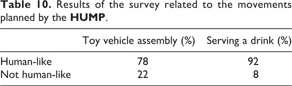
In section “An example of an obstacles-free move movement,” one example of an unconstrained reaching movement is analyzed in a workspace without obstacles. In section “Toy vehicle assembly,” the proposed planner is tested in a scenario that resembles a typical joint assembly task, while, in section “Serving a drink,” a task is planned to serve a drink to impaired human partners in a household environment. A qualitative user’s rating of the movements generated in these latter scenarios is provided in section “Subjective user ratings.” Finally, in section “Naturalistic obstacles-avoidance,” the proposed human-like obstacles-avoidance mechanism is studied more in details and compared with recent studies on human hand collisions-free trajectories.
An example of an obstacles-free move movement
We begin with the planning of a simple move movement from a start hand pose to a target hand pose with the same orientation. This simple experiment allows us to understand how the proposed method performs in solving uncomplicated planning problems. Since the avoidance of collisions is not intentionally involved, there is no need to integrate a back-and-forth movement (see section “Transport back-and-forth movement”), and, therefore, the move movement is only composed by a transport direct movement (equation (22)). The hand path and the velocity profile of the move movement generated by the HUMP are illustrated in Figure 6.
Example of a move movement planned by the HUMP in the absence of obstacles (NJS = 24.8, NMU = 1, solving time = 567 ms). (a) Hand position and (b) hand velocity.
Given an NJS of 24.8 and the NMU of 1, the HUMP generated a trajectory that is clearly smooth with a human-like bell-shaped hand velocity profile. Additionally, the proposed method only required 567 ms to generate this trajectory.
Toy vehicle assembly
This scenario is prepared by taking inspiration from our previous work.7,8,58 Here a construction paradigm in which a robot and a human partner have to jointly assemble a toy vehicle (Figure 7(b)) from component parts that are initially distributed on a table in front of ARoS (Figure 7(a)). Since for safety reasons ARoS and the human partner operate in separate workspaces, the joint action paradigms include the transfer of objects between the coworkers as a subtask. This scenario allows to analyze the proposed planner in goal-directed action sequences composed of pick, place, and move movements. We decided to address simple sequences of the action to maintain the focus on the evaluation of the human-likeness of the motion rather than on the complexity of the object manipulation. In particular, we analyze how the different movement phases are concatenated together to reach a continuous stream of motion that humans exhibit in manipulative tasks.
Toy vehicle assembly. (a) Pieces of the toy vehicle and (b) the toy vehicle fully assembled.
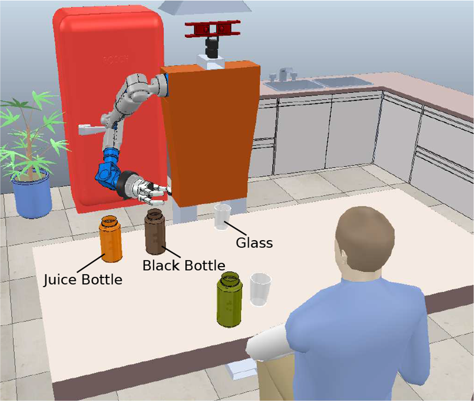
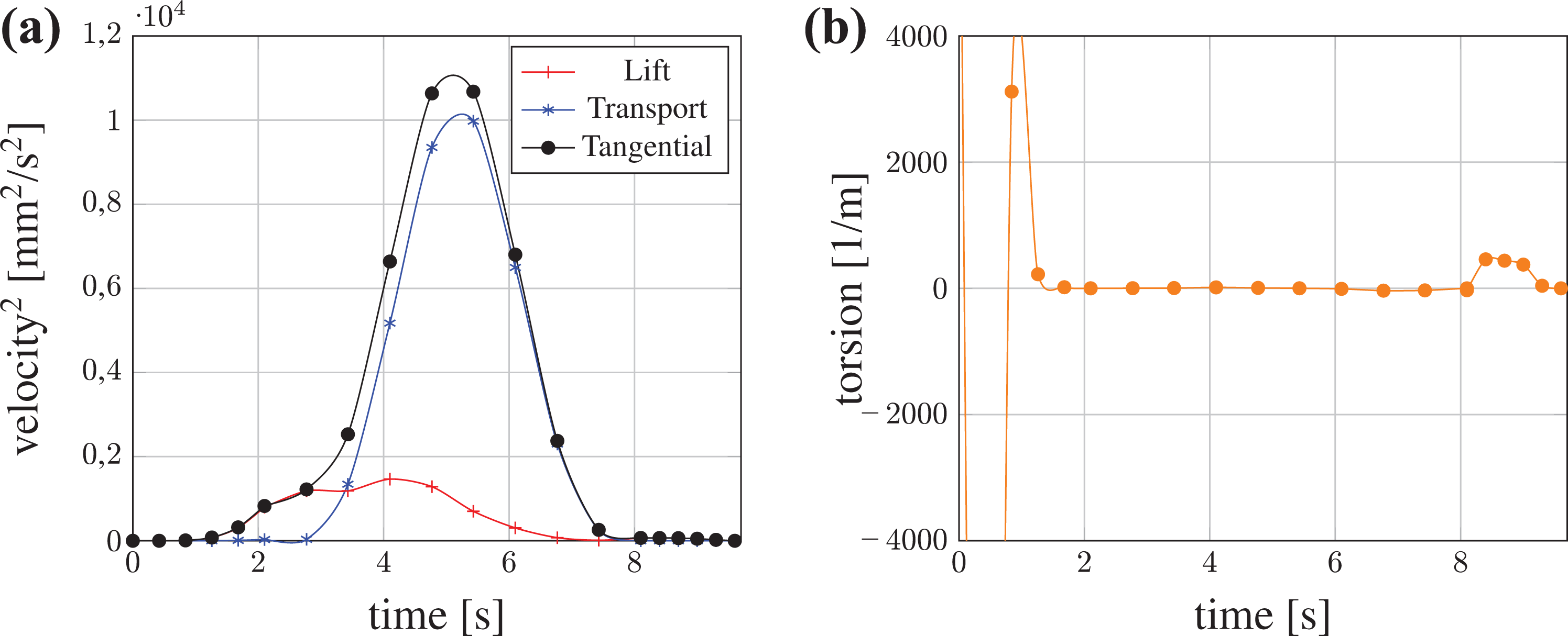
As an example of manipulation, we present here the subtask of assembling the magenta column shown in Figure 8. This task starts with the human partner holding out the column for the robot. ARoS reaches to grasp (Figure 8(a) and (b)) and pick up the column at the exchange position (Figure 8(b)) and then places it into the corresponding (magenta) hole into the base platform (Figure 8(c)). Finally, ARoS returns to its SP (Figure 8(d)). The pick and the place movements are composed by three phases: the transport, the approach, and the retreat phases. As described in the fifth section, each phase has a given hand target pose, which is the same for every planner used in this test.
Four snapshots that show the sequence of the movements planned by the HUMP in the toy vehicle scenario. The complete video can be seen at the link https://youtu.be/duDCGcrC3k4. (a) Start posture; (b) Pick movement; (c) Place movement; and (d) Move movement.
The kinematic features of the pick movement planned by the HUMP are illustrated in Figure 9. Qualitatively, the pick movement is featured by a unimodal bell-shaped hand velocity profile and a quasi-rectilinear hand path. Additionally, the hand only stops at the moment of grasping and it is featured by an approach phase in the vicinity of the object to grasp. Quantitatively, the pick movement has a single-peaked hand velocity profile (NMU = 1), its NJS is 1798.28 and its solving time is 2823 ms.
Pick movement planned by HUMP (NJS = 1798.28, NMU = 1, Solv. time = 2823 ms). (a) Hand position and (b) hand velocity.
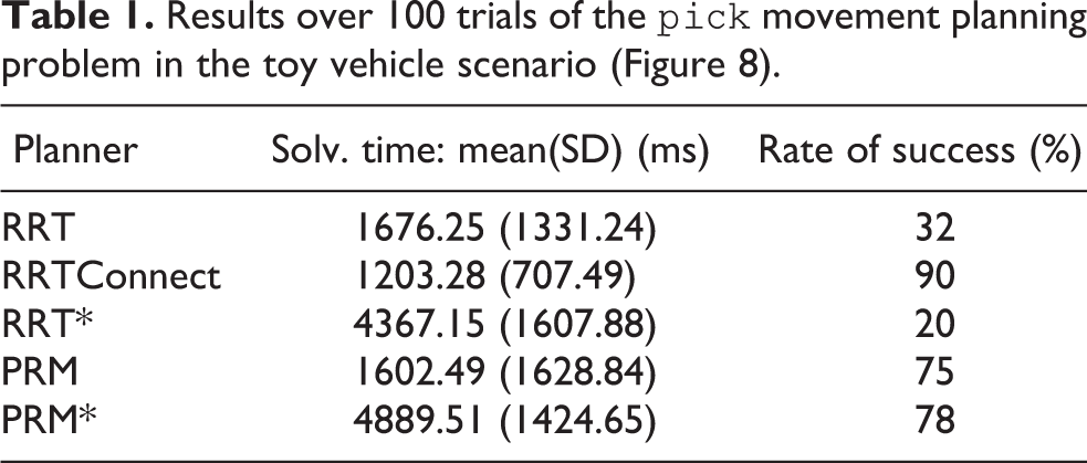
Table 1 shows the required time and the rate of success of the sampling-based planners in solving the same planning problem. The reported solving time is not only referred to the time required by a selected planner for generating a collisions-free path but also includes the default MoveIt! KDL IK implementation,59 which provides a feasible TP, and the default iterative parabolic time parametrization, which provides the time steps between adjacent points of the path. This table reveals that RRTConnect solved the pick movement planning problem 90 times over 100 trials. The other sampling-based planners showed a much lower success rate and RRTConnect is also the fastest planner with the smallest standard deviation. On the contrary, PRM showed the biggest standard deviation revealing an evident right-skewed distribution of solving time values.
Results over 100 trials of the pick movement planning problem in the toy vehicle scenario (Figure 8).
Planner
Solv. time: mean(SD) (ms)
Rate of success (%)
RRT
1676.25 (1331.24)
32
RRTConnect
1203.28 (707.49)
90
RRT*
4367.15 (1607.88)
20
PRM
1602.49 (1628.84)
75
PRM*
4889.51 (1424.65)
78
The hand position and velocity of the place movement planned by the HUMP are illustrated in Figure 10. Due to the retreat phase of the previous pick movement, the trajectory starts with a nonzero velocity and acceleration. The transport phase is featured by a unimodal hand velocity profile that ends with an accentuated approach phase, which brings the column into the hole of the base. Moreover, the hand only stops during the release transition and then retreats away from the placing location. Again, the HUMP generates a trajectory with NMU = 1, but its NJS is significantly greater (15702.5) than that one of the previous pick movement. This is due to the endpoint precision required in placing the column, which is featured by a prominent hand velocity profile during its approach phase.
Place movement planned by HUMP (NJS = 15702.5, NMU = 1, Solv. time = 2261 ms). (a) Hand position and (b) hand velocity.
As summarized in Table 2, the rate of success over 100 trials shows that this planning problem was complex for all the tested sampling-based planners. The HUMP required a solving time (2261 ms) that is generally greater than that one needed by RRT, PRM, and RRTConnect but significantly smaller than that one required by RRT* and PRM*.
Results over 100 trials of the place movement planning problem in the toy vehicle scenario (Figure 8).
Planner
Solv. time: mean (SD) (ms)
Rate of success (%)
RRT
1345.61 (892.02)
23
RRTConnect
1303.45 (830.31)
33
RRT*
5148.77 (76.05)
13
PRM
1007.24 (816.18)
34
PRM*
4227.13 (1647.97)
39
The final movement of this task is a move movement that brings the robotic arm-hand back to its SP. The kinematic characteristics of the movement planned by the HUMP are illustrated in Figure 11. The bell-shaped single-peaked hand velocity profile starts from a nonzero value, due to the retreat phase of the previous place movement. Quantitatively speaking, the NMU is 1 and the NJS is very small (18.06), which is consistent with a very smooth bell-shaped hand velocity profile with a single peak. Compared with the other planners, the HUMP produces the move movement in a minimum amount of time of 847 ms, which is also an index of the low complexity of the planning problem that has been solved successfully in most of the trials (Table 3).
Move movement planned by the HUMP (NJS = 18.06, NMU = 1, Solv. time = 847 ms). (a) Hand position and (b) hand velocity.
Results over 100 trials of the move movement planning problem in the toy vehicle scenario (Figure 8).
Planner
Solv. time: mean (SD) (ms)
Rate of success (%)
RRT
5264.53 (143.64)
45
RRTConnect
1527.33 (415.87)
99
RRT*
5169.89 (52.52)
100
PRM
5507.87 (414.20)
97
PRM*
5953.54 (277.79)
96
The concatenation of the three movements of this task is illustrated in Figure 12. Since the robot starts and ends its motion with the same posture, the start and the target hand positions correspond to the same point in the space (Figure 12(a)). The hand velocity profile, shown in Figure 12(b), reveals that the grasp and the ungrasp transitions clearly define the first two phases of the place movement, while its retreat phase connects to the move movement. These transitions are the only time instants when arm and hand come to rest during the entire movement duration.
The complete task planned by the HUMP. (a) Hand position and (b) hand velocity.
Serving a drink
To further test the capacity of the HUMP to generate human-like movements in complex tasks relevant for HRI, we have chosen as a second example a household environment in which a robot helper prepares a drink. A human partner watches a sequence of robot actions that includes pouring orange juice into a glass. The workspace of the robot consists of various bottles and glasses that are arranged on a table (Figure 13). The robot has to pick up the (open) bottle with orange juice, transport it to a pouring position close to the glass while avoiding the collision of its body with a black bottle located in between the juice bottle and the target location. The robot pours the liquid into the glass, moves the bottle again into an upright position to prevent spilling during transportation, and finally repositions the bottle at its initial location. For the pouring action, we assume that the bottle moves mostly in a two-dimensional plane so that the orientation can be modelled by a one-dimensional tilt angle. This is a realistic assumption for a pouring action in which the source container is taller than the receiving container.60 Since an autonomous flow control goes beyond the scope of this article, we further assume that the desired tilt angle and the time interval for pouring are predefined. The pouring stops when the bottle is moved into an upright position again, which we call the post-pouring phase.
Drink serving scenario.
As illustrated in Figure 14, the planning and execution of the entire action sequence can be segmented in six movements defined by specific subgoals. The sequence starts with a reach-to-grasp movement directed toward the juice bottle (pick movement, Figure 14(b)), followed by moving the bottle to the pouring position (place movement 1, Figure 14(c)), pouring the juice (pouring movement, Figure 14(d)), reorientating the bottle (post-pouring movement, Figure 14(e)), placing the bottle at the initial position (place movement 2, Figure 14(f)), releasing the bottle, and moving the arm back to its SP (move movement, Figure 14(g)).
Seven snapshots showing the sequence of the movements planned by the HUMP in the drink serving task. The complete video can be seen at the link https://youtu.be/i2ytpSQViy8. (a) Start posture; (b) Pick movement; (c) Place movement 1; (d) Pouring movement; (e) Post-pouring movement; (f) Place movement 2; and (g) Move movement.
Figure 15 illustrates the kinematic characteristics of the pick movement planned by the HUMP. The movement is composed of a transport phase with a bell-shaped hand velocity profile, a relatively long approach phase toward the bottle to be grasped and a retreat phase that detaches the bottle from the table. The movement has a single NMU and an NJS equals to 6377.39, which suggests a relative low level of complexity. The latter seems to be confirmed by the high rates of success in Table 4, even though RRT and RRT* failed more often than the other planners. Additionally, the HUMP solved the pick problem in significantly less time than the other optimization-based planners RRT* and PRM* but took generally longer than the fastest planners RRT and RRTConnect (Table 4).
Pick movement planned by HUMP in the drink serving task (NJS = 6377.39, NMU = 1, solving time = 1225 ms). (a) Hand position and (b) hand velocity.
Results over 100 trials of the pick movement in the drink serving scenario (Figure 14).
Planner
Solv. time: mean (SD) (ms)
Rate of success (%)
RRT
1030.07 (673.16)
57
RRTConnect
390.36 (87.65)
74
RRT*
4380.29 (1550.46)
48
PRM
670.54 (163.93)
69
PRM*
4232.59 (1782.33)
75
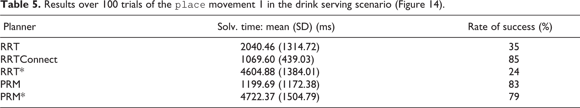
The hand position and velocity profile of the first place movement are shown in Figure 16(a) and (b), respectively. This movement is formed by a transport phase and an approach phase. A retreat phase is not desired because the robot needs holding the bottle for the subsequent pouring action. The transport phase is featured by a single-peaked, bell-shaped velocity profile and the approach phase is shorter compared to the pick movement. The HUMP generated the movement with a small NJS of 933.52 and a single NMU in 848 ms, which is on average the minimum amount of time when compared to all probabilistic planners (Table 5).
Place movement 1 planned by the HUMP in the drink serving task (NJS = 933.52, NMU = 1, solving time = 848 ms). (a) Hand position and (b) hand velocity.
Results over 100 trials of the place movement 1 in the drink serving scenario (Figure 14).
Planner
Solv. time: mean (SD) (ms)
Rate of success (%)
RRT
2040.46 (1314.72)
35
RRTConnect
1069.60 (439.03)
85
RRT*
4604.88 (1384.01)
24
PRM
1199.69 (1172.38)
83
PRM*
4722.37 (1504.79)
79
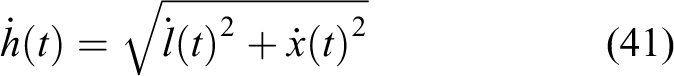
Also the pouring movement is composed of two phases, the transport and the approach phases, at the end of which the juice is poured into the glass. As can be seen in Figure 17(b), the transport phase is featured by a low-velocity profile of the tangential hand velocity in its early seconds of motion and a second bigger velocity peak during the rest of the motion. This movement is thus characterized by an NMU of two, which is often observed in human hand motion as well, in particular, in the proximity of an obstacle (here the glass) that has to be avoided.20 In this particular case, the hand detour in position is mainly caused by its high rate of change in orientation, which contributes in giving a rise to a double peak in the tangential velocity of the hand (more details are given by Rosenbaum et al.,20 Lommertzen et al.,61 Grimme et al.,62 and in section “Naturalistic obstacles-avoidance”). Table 6 shows that HUMP solved this planning problem in 1603 ms, generally much faster than RRT* and PRM*, but on average much longer than RRTConnect, which was rather the fastest planner. The rate of success of the probabilistic planners over 100 trials revealed that this planning problem was quite complex to solve with the PRM* giving the highest rate.
Pouring movement planned by the HUMP in the drink serving task (NJS = 5504.86, NMU = 2, solving time = 1603 ms). Hand position and (b) hand velocity.
Results over 100 trials of the pouring movement in the drink serving scenario (Figure 14).
Planner
Solv. time: mean (SD) (ms)
Rate of success (%)
RRT
1546.19 (1262.89)
47
RRTConnect
800.24 (357.29)
62
RRT*
4484.59 (1455.44)
29
PRM
2120.62 (1021.04)
53
PRM*
4283.70 (1862.24)
64
The post-pouring movement is meant to rotate the bottle toward a given orientation to avoid that the remaining juice drops. Since in this case an accurate approach phase is not required and the bottle cannot be released, this movement consists of the transport phase only. Similarly to the pouring movement, Figure 18 illustrates that the transport phase is featured by an accentuated biphasic hand velocity profile (NMU is 2). Similarly here, the rise of two peaks is due to a significant detour of the hand that changes its orientation in a relatively short period of time.20 The NJS score (199.65) indicates that the HUMP generated a very smooth movement and its planning time of 620 ms is on average slower than the fastest planner (RRTConnect), but fairly faster than the other probabilistic planners that generally scored a good rate of success (Table 7).
Post-pouring movement planned by HUMP in the drink serving task (NJS = 199.65, NMU = 2, solving time = 620 ms). (a) Hand position and (b) hand velocity.
Results over 100 trials of the post-pouring movement in the drink serving scenario (Figure 14).
Planner
Solv. time: mean (SD) (ms)
Rate of success (%)
RRT
746.45 (587.38)
62
RRTConnect
383.40 (185.97)
84
RRT*
4813.81 (1072.94)
47
PRM
1057.89 (1102.26)
81
PRM*
4226.54 (1751.17)
83
The second place movement transports the juice bottle back to its initial position and orientation. This movement is composed by a transport, an approach phase, and a retreat phase. As illustrated in Figure 19, the hand path during the transport phase is highly curved to avoid collisions with the black bottle. The hand velocity profile is unimodal and bell-shaped with a smooth transition to the low-velocity approach phase. The hand stops during the ungrasp transition, which starts the retreat phase. This movement clearly has an NMU equals to 1 and a restrained NJS of 5566.22. As it is shown in Table 8, the planning problem was quite complex except for RRTConnect that had a rate of success of 73%. Moreover, RRTConnect was generally the fastest planner and the HUMP was on average lightly slower than it with 1375 ms of required solving time.
Place movement 2 planned by HUMP in the drink serving task (NJS = 5566.22, NMU = 1, solving time = 1375 ms). (a) Hand position and (b) hand velocity.
Results over 100 trials of the place movement 2 in the drink serving scenario (Figure 14).
Planner
Solv. time: mean (SD) (ms)
Rate of success (%)
RRT
1858.56 (1080.45)
27
RRTConnect
1038.63 (510.94)
73
RRT*
5110.14 (564.79)
36
PRM
1866.93 (966.32)
69
PRM*
4301.50 (1744.09)
60
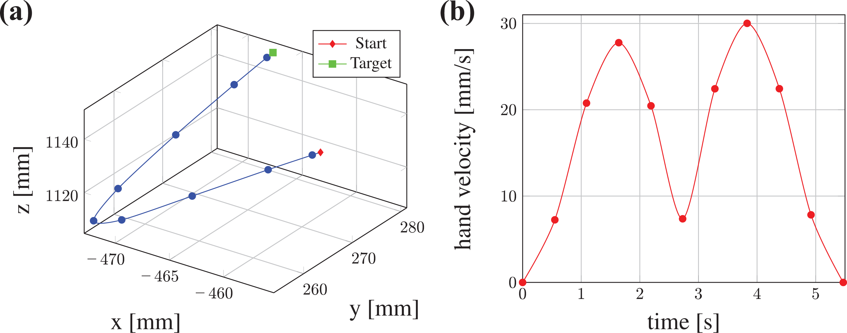
After having released the bottle, ARoS moves the hand back to the start pose by the mean of a move movement that is shown in Figure 20. Interestingly, this movement has zero NMU despite the occurrence of two velocity peaks which are, however, not detected since the increase/decrease of hand velocity between the adjacent maximum and minimum does not exceed the threshold value for defining a movement unit. Importantly, the evaluation of the retreat phase of the previous movement and the move movement together (Figure 21) reveals that HUMP generated a human-like reaching movement characterized by an NMU score of one and a bell-shaped velocity profile. The proposed method planned a very smooth move movement with an NJS of 24.57. Moreover, Table 9 shows that all the probabilistic planners, except RRT*, scored a high rate of success suggesting a low complexity of the planning problem. This is also confirmed by the fact that the HUMP only required 297 ms to generate a trajectory, which marks it as the fastest planner in this particular case.
Move movement planned by HUMP in the drink serving task (NJS = 24.57, NMU = 0, solving time = 297 ms). (a) Hand position and (b) hand velocity.
Results over 100 trials of the move movement planning in the drink serving scenario (Figure 14).
Planner
Solv. time: mean (SD) (ms)
Rate of success (%)
RRT
5207.98 (107.87)
93
RRTConnect
1855.15 (431.90)
100
RRT*
5224.96 (76.60)
53
PRM
5416.57 (542.50)
99
PRM*
5888.02 (295.42)
98
Retreat stage of the place movement 2 in Figure 17 plus the move movement in Figure 20 planned by the HUMP in the drink serving task (NMU = 1). (a) Hand position and (b) hand velocity.
Figure 22 shows the hand path and hand velocity profile of the entire movement sequence defining the drink serving task. The start and the target pose of the task are the same because the robot starts and ends with the same posture (Figure 22(a)). The approach phase is most prominent in the pick movement at the beginning of the task to guarantee a precise grasping behavior. Furthermore, we note that the hand stops five times between the start and the end of the task, namely for the grasp transition, when the bottle has reached the pouring position, while pouring the juice into the glass, during the reorientation of the bottle to avoid spilling of liquid, and for the ungrasp transition.
Complete movement sequence of the drink serving task planned by the HUMP. (a) Hand position and (b) hand velocity.
Subjective user ratings
In this section, we report the results of a short survey we conducted to qualitative evaluate the human-likeness of the movements planned by the HUMP. The aim was to assess the perception of naive users when watching trajectories with human-like characteristics in the toy vehicle assembly (Figure 7) and in the drink serving (Figure 13) scenarios.
In this experiment, 50 participants (21 female and 29 male, age between 21 and 54 years) were asked to label videos of ARoS moving its right upper limb in the assembly paradigm (Figure 8) and while serving a drink (Figure 14). The participants watched the videos through a web-based platform to ensure well-controlled and repeatable conditions for all subjects. The videos were also silenced to avoid any influence of robot motor noise on the personal judgment. The two tasks and their objectives were first fully described. Since they represent common tasks of object manipulation, one can assume that each participant could make expectations on how a human-like execution of a task should look like. For each task, the videos of the movements generated by the HUMP were presented sequentially in a random order. After each video, the participant had to exclusively choose between the labels “human-like” and “not human-like.”
The results of the user ratings, summarized in Table 10, show that the HUMP reached 92% human-like judgments in the drink serving scenario and 78% in the toy vehicle assembly. Therefore, in both scenarios, the trajectories planned by the HUMP were strongly perceived as natural and human-like by the vast majority of the observers.
Results of the survey related to the movements planned by the HUMP.
Toy vehicle assembly (%)
Serving a drink (%)
Human-like
78
92
Not human-like
22
8
Interestingly, these findings may be interpreted in support of the notion of action perception as an intrinsically predictive activity.4,7,63 Since the participants knew the goals and the subgoals of the movement sequences before watching ARoS executing a task, they were able to predict possible motor solutions based on their own mental representations. Based on this point of view, the degree of mismatch between an internal motor simulation and the observed upper-limb motion of ARoS may explain whether an action is perceived as human-like or not.
Naturalistic obstacles-avoidance
The toy vehicle assembly and the drink serving tasks show that the HUMP generates smooth trajectories that avoid undesired collisions with obstacles or the object being manipulated. Given that several studies on human obstacles-avoidance have reported velocity profiles with a characteristic double-peak structure,20,62 our claim that the HUMP generates kinematically human-like movement profiles requires further investigation. To better understand how the position and the height of an obstacle might affect the hand kinematics during collisions-avoidance, we conducted additional experiments in a setup inspired by a recent study on human strategies for collisions-prevention in a three-dimensional workspace.62
The top view of the experimental setup shown in Figure 23 illustrates the spatial layout. ARoS had to reach for a cylindrical object (a bottle) placed on a table in front of the robot and transport it from the start position to one of two possible target positions: Target 1 (T1) at a distance 30 cm away from the starting position in straight ahead direction, and Target 2 (T2) shifted 15 cm to the right of T1, thus located in a direction diagonal to the starting position. For each target, an obstacle was located at mid-distance between the start and the target either on the left or on the right of the straight line connecting them. The obstacle is a cylinder with a diameter of 8 cm, which could be either tall (28 cm in height) or small (14 cm in height). Table 11 summarizes the labels we use in the text to describe the different conditions. The last condition in this table indicates if the obstacle avoidance mechanism is used. In other words, whether the back-and-forth movement (equation (14)) is superimposed on the direct movement (equation (22)) to obtain the trajectory in equation (23) or only the direct movement is planned. Figure 24 illustrates two possible combinations in which only the height of the obstacle is changed.
Spatial layout of the experimental setup. For details, see the text. Obstacle locations O1 and O2 were only applied in combination with target T1, whereas obstacles locations O3 and O4 were combined with target T2.
Description of the symbols used in the experiments.
Target position
Obstacle position
Obstacle height
Obstacle avoidance
Straight
Diagonal
Left
Right
Small: 14 cm
Tall: 28 cm
Yes
No
T1
T2
O1
O3
O2
O4
S
T
Y
N
Configuration T2O4 with a small (T2O4S) and a tall obstacle (T2O4T).
For the sake of brevity, we report here only the results of four experimental conditions and three videos, which nevertheless allow us to qualitatively compare the results with fundamental findings of the study conducted by Grimme et al.62 Since we were primarily interested in the obstacle-avoidance movement, the analysis included the retreat phase of the pick movement and the transport plus the approach phases of the place movement (see section “Classification and segmentation of a movement”). Following the paradigm presented by Grimme et al.,62 we measured the torsion of the hand, , (equation (39)) to verify that avoiding an obstacle naturally generates approximately planar movements
In equation (39), r is the three-dimensional position of the hand along its path, which brings numerical problems when the velocity and the acceleration of the hand are close to zero. This is visible in the results at the beginning and at the end of a movement, but it does not relate to our conclusions. In addition, we decomposed the tangential velocity into a transport and a lift/descend component because this decomposition allows to understand the occurrence of a double peak structure in the tangential speed profile.62 The transport component is obtained by projecting the path on the straight line connecting the start position to the target position, which corresponds to the Euclidean x-component (for configurations T2, the frame of Cartesian coordinates is rotated accordingly), and the lift/decent component is the orthogonal complement defined by equation (40).
The hand tangential velocity is then given by equation (41)
Figures 25 and 26 show the results of the planning process in configuration T2O4TN, which is without obstacle avoidance and with a tall obstacle present at position O4. As expected, the hand collides with the mid-way obstacle. The hand path is planar during most of the time and the resulting velocity profile is defined by the dominant, bell-shaped transport component and a negligible lift component.
Hand velocity components and hand torsion of the manipulation in configuration T2O4TN. (a) Hand velocity components and (b) hand torsion.
(a) to (c) Three snapshots that show the movement planned by the HUMP in the configuration T2O4TN. The complete video can be seen at the link https://youtu.be/3hZJb4rkgaI.
An example of the same configuration with obstacle avoidance (T2O4TY) is shown in Figures 27 and 29. A significant lift/descend component is needed to avoid the tall cylinder that, however, has a single velocity peak. Since a movement path with relative large safety margin to the obstacle has been planned, this suggests that the tangential velocity profile is linked to the path geometry and not directly coupled to the obstacle passage. Configuration T1O2TY with a tall obstacle, in contrast, produced a tangential velocity profile with a clear double peak (Figures 28 and 30). This comes from the much larger peaks in the lift/descend component compared to configuration T2O4TY (see Figures 27 and 29).
(a) to (c) Three snapshots that show the movement planned by the HUMP in the configuration T2O4TY. The complete video can be seen at the link https://youtu.be/3hZJb4rkgaI.
(a) to (c) Three snapshots that show the movement planned by the HUMP in the configuration T1O2TY. The complete video can be seen at the link https://youtu.be/3hZJb4rkgaI.
Hand velocity components and hand torsion of the manipulation in configuration T2O4TY. (a) Hand velocity components and (b) hand torsion.
Hand velocity components and hand torsion of the manipulation in configuration T1O2TY. (a) Hand velocity components and (b) hand torsion.
In contrast, in configuration T1O1SY, the small size of the cylinder did not require a significant lift/descend component (which, however, shows a double peak). The results of this configuration are interesting because even though there is a double peak in the lift component, the latter has not a sufficient amplitude to raise a second peak in the total component (compare Figure 31(a) with Figure 30(a)). The resulting tangential velocity profile almost coincides with its transport component and the motion is essentially planar (Figure 31).
Hand velocity components and hand torsion of the manipulation in configuration T1O1SY. (a) Hand velocity components and (b) hand torsion.
The results of the obstacle-avoidance experiments not only reproduce the observed planarity of the movements but are qualitatively in good agreement with other findings of Grimme et al.62 as well. The authors consistently observed a zero crossing of hand velocity during the transition from lift to descend. Moreover, the magnitude of the lift/descend component, which was often correlated with the height of the obstacle, defines whether the speed profile is uni- or bi-modal.
However, our experiments in the robotics domain also indicate that the size of the obstacle might not be the only factor affecting the hand velocity profile. Additional task demands represented on a higher cognitive planning level like accuracy and safety that influence the choice of, for instance, the clearance distances (equations (10) and (19)) or the number of steps used for time discretization (equation (36)), might affect the hand kinematics as well.
Conclusions
With the purpose of improving nonverbal communication between humans and robots that are involved in shared tasks, efficient and fluent interactions can be certainly achieved when robots act more like humans do.11 Most of the current global methods of human-like arm motion generation fail at reproducing the biological kinematic features of human upper-limb movements during manipulation and obstacles-avoidance. For this reason, we have here proposed a human-like upper-limb motion planner (HUMP) to release a comprehensive framework available for the robotics domain. This is a motion planning algorithm that aims at replicating different human motor control strategies concerning the actions of reaching, prehension, and manipulation.
Following the conceptual ideas of the posture-based motion planning model,20,21 the underlying assumptions in the proposed algorithm are (1) the planning process, which encapsulates two nonlinearly constrained optimization problems, starts with the selection of a TP, followed by the selection of a BP to define a human-like collisions-free trajectory; (2) a task is formulated as a constrained hierarchy that considers a naturalistic avoidance of obstacles, a travel cost following the minimum angular jerk principle, and the respect of the physical joint limits; (3) collisions with objects are avoided by the superimposition of a direct movement toward the TP with a back-and-forth movement, which goes toward a BP and back to the SP. Even though the model proposed by Rosenbaum et al.20 and Vaughan et al.21 has been of significant inspiration for this work, the HUMP also substantially differs from it in many aspects. For example, the selection of a TP does not go through a weighted evaluation of a group of most promising posture candidates that are stored from past experienced motion20 but is obtained by minimizing the overall angular jerk of a direct movement (see section “TP selection”). Additionally, it also worth noting that the proposed search for an optimal TP overcomes issues of convergence failures and of inactivity on local solutions, which are typically detected when a Newton-based method is applied in numerical inverse kinematics.43 Indeed, the application of the solver IPOPT52 permits to actively search for a feasible optimal solution and, consequently, reduce false-negative failures due to the presence of physical joint limits. Moreover, despite the non-convexity of the formulated optimization problems, our previous experiments demonstrated that, in few motion planning tests, IPOPT could efficiently avoid local optima and reach global solutions.64 Not dissimilarly, the selection of an optimal BP and the proposed formulation of the back-and-forth movement also differ from what was initially introduced by Rosenbaum et al.20 to ensure a correct composition of a collisions-free trajectory and add a flexible tuning of the planner without losing the desired human-like characteristics of obstacles-avoidance.
The proposed framework for human-like upper-limb motion planning not only addresses simple reaching actions (move movements) but intends to replicate the kinematics features that have been observed in human manipulative tasks (sequences of pick and place movements). For this reason, the proposed planning process produces a movement from the generation of its composing phases of action, namely: the transport, the approach, and the retreat phases (see section “Classification and segmentation of a movement”). While the transport phase is formulated according to the primary concepts of the posture-based motion planning model,20,21 the approach and the retreat phases are defined to mimic the kinematics of human accurate manipulation. Specifically, studies on human accurate manipulation by Milner23 have been of significant inspiration to formulate the trajectories of the approach and the retreat phases of action (see sections “Approach direct movement” and “Retreat direct movement”).
Unlike the HUMP, other approaches that can replicate human-like arm-hand kinematics are based on examples of human-recorded trajectories.33,34,65–67 These methods need to solve the difficult correspondence problem for a motion mapping between agents with different embodiments. Moreover, motion capture data may not be available or difficult to record for a specific task. This does not exclude, however, that existing information about human poses may be integrated into the HUMP algorithm to bias, for instance, the selection of the target and BPs. Additionally, in the current literature, other techniques of human-like arm-hand motion generation neglect the important dimension of time and risk the formation of unrealistic and nonhuman velocities. On the contrary, the proposed HUMP explicitly computes a human-like duration of a movement by applying the Fitts’ Law46 to the angular displacement of the joints. To the best of our knowledge, a similar time parametrization for motion planning has never been proposed in the robotics domain (see section “Human-like time parametrization”).
We also tested the capacity of the planner to generate entire sequences of object-directed movements in two paradigms adopted from our previous work on action coordination in collaborative tasks.7,8,58 The assembly paradigm was segmented into a pick, a place, and a move movements. The resulting movement phases appeared in general not jerky with smooth transitions and few stops of the robotic hand. The quantitative smoothness measures applied for each individual movement confirmed this observation. The HUMP consistently achieved an NMU score of one and performed very well in the jerk-based measure with a NJS in general small according to the motion being planned. Since in the robotics community there is not a generally accepted metric to quantify the similarities between robotic and human arm movements, our work can also be seen as a contribution toward a possible standard. We adopted smoothness measures—the NJS and the NMU (c.f. the seventh section)—that have been used in the past to discriminate between well-coordinated and impaired human motion.
The household task of serving a drink introduced new challenges for the planners, in particular for the obstacles-avoidance mechanism. The task was segmented into six movements that included the avoidance of a black bottle during the transport of the orange bottle toward the pouring position and the avoidance of the glass during the pouring and post-pouring movements. The concatenation of different phases led to the same conclusions concerning the smoothness evaluation as found in the assembly task. The HUMP generated trajectories with human-like values of NMU and NJS for each movement and consequently also for the sequence as a whole.
Computational cost is a major concern of all optimization approaches to trajectory planning. Therefore, we compared the planning time required by the proposed HUMP with the average planning time (the standard deviation is large in general) of successful trials of five popular probabilistic planners. Considering the movements individually, the HUMP ranked on average always better than RRT* and PRM* and often comparably with RRT, RRTConnect, and PRM. We conclude that the generation of a movement with human-like features does not come at the expense of a significant slower planning process. The limited computational cost of the proposed planner encourage us to further investigate on multi-threading replanning strategies that can be required in dynamic unstructured environments. During the execution of a movement, for instance, the HUMP might be able to plan other movements in parallel threads to suit eventual changes in the workspace.
The results of the subjective ratings of naive users watching ARoS in action are consistent with the idea that the smoothness measures applied for the quantitative evaluation are good predictors for perceiving robot motion as human-like or not. The HUMP got a human-like score of 92% for the drink serving scenario and 72% for the assembly task. Since no further information was requested from the participants, one can only speculate why the seemingly simpler assembly sequence got a lower score than the longer and more complex drink serving sequence. We plan to address in the future user study the impact of biological versus nonbiological robot motion on human behavior applying time-based evaluation metrics for joint action tasks (e.g. reaction/waiting time).
The fact that our experiments were not sufficiently exhaustive in describing the mechanism of a biphasic hand velocity profile in the presence of obstacles motivated us to additionally investigate the emergent naturalistic obstacles-avoidance behavior. We followed an experimental design (introduced by Grimme et al.62) involving human participants in the avoidance of obstacles obstructing the shortest path from a start and a goal position. The results obtained with the HUMP qualitatively reproduced a main finding of the study: a decomposition of the tangential hand velocity in a transport and a lift/decent component revealed that a zero crossing of the latter component is responsible for the nature of the hand speed profile. A bimodal profile occurs when the lift/decent component is prominent, which may depend on the height of the obstacle but also on other more cognitive factors, such as accuracy and safety margins.
Our work is, however, limited in many ways and there are several issues that need further attention. For instance, the geometrical models adopted to represent the objects being manipulated, the obstacles, and the body of the robot are not sufficiently precise to cover any physically feasible planning problem. In particular, when obstacles are in close proximity to a target object, the present version of the HUMP may not find a grasping pose even if the robotic system is in principle able to reach the target. Another issue concerns the extension of the HUMP motion library to cover robotic platforms that are not fully humanoids. For instance, it can be expected that a detached industrial robotic arm with a human-like joints-space configuration may facilitate to some extent HRIs if it moves in a way that resembles a human arm movement.57,65 However, it should be noticed that, in comparison with an industrial robot, the benefit of human-like motion seems to be significantly larger for an artificial agent that also mimics the human form.17,68 Finally, while the experiments with ARoS have shown that the computational cost of the HUMP algorithm is comparable with five popular sampling-based planners, we want to explore possibilities to further speed up the optimization processes. One way to do this is to start the search for a TP and a BP and a BP with an appropriate initial guess (e.g. derived from past experiences or demonstrations) and not from the SP of the manipulator like in the present implementation.
It has been shown that during cooperative interactions with peers, humans cannot help but predict the future course of their partners’ goal-directed movements in the service of fluent joint action coordination.4 Generating movements with human-like characteristics is thus a crucial design principle for social robots that are supposed to interact with users in an intuitive and effortless manner.11 An important step forward in this direction is made by the proposed planner, which derives collisions-free trajectories featuring fundamental kinematic regularities observed in human upper-limb motion. The proposed planner is an important step forward in this direction because it can efficiently derive collisions-free trajectories that meet fundamental kinematic regularities observed in human upper-limb motion.
Supplemental material
Supplemental Material, sj-7z-1-arx-10.1177_1729881421998585 - A Human-like Upper-limb Motion Planner: Generating naturalistic movements for humanoid robots
Supplemental Material, sj-7z-1-arx-10.1177_1729881421998585 for A Human-like Upper-limb Motion Planner: Generating naturalistic movements for humanoid robots by Gianpaolo Gulletta, Eliana Costa e Silva, Wolfram Erlhagen, Ruud Meulenbroek, Maria Fernanda Pires Costa and Estela Bicho in International Journal of Advanced Robotic Systems
Supplemental material
Supplemental Material, sj-7z-2-arx-10.1177_1729881421998585 - A Human-like Upper-limb Motion Planner: Generating naturalistic movements for humanoid robots
Supplemental Material, sj-7z-2-arx-10.1177_1729881421998585 for A Human-like Upper-limb Motion Planner: Generating naturalistic movements for humanoid robots by Gianpaolo Gulletta, Eliana Costa e Silva, Wolfram Erlhagen, Ruud Meulenbroek, Maria Fernanda Pires Costa and Estela Bicho in International Journal of Advanced Robotic Systems
Supplemental material
Supplemental Material, sj-pdf-1-arx-10.1177_1729881421998585 - A Human-like Upper-limb Motion Planner: Generating naturalistic movements for humanoid robots
Supplemental Material, sj-pdf-1-arx-10.1177_1729881421998585 for A Human-like Upper-limb Motion Planner: Generating naturalistic movements for humanoid robots by Gianpaolo Gulletta, Eliana Costa e Silva, Wolfram Erlhagen, Ruud Meulenbroek, Maria Fernanda Pires Costa and Estela Bicho in International Journal of Advanced Robotic Systems
Footnotes
Declaration of conflicting interests
The author(s) declared no potential conflicts of interest with respect to the research, authorship, and/or publication of this article.
Funding
The author(s) disclosed receipt of the following financial support for the research, authorship, and/or publication of this article: This work was funded by the EU Project FP7 Marie Curie NETTNeural Engineering and Transformative Technologies (ID 289146), the FCT PhD grant (ref. SFRH/BD/114923/2016), the FCT Project UID/MAT/00013/2013, and the FCT within the R&D Units Project Scope: UIDB/00319/2020.
ORCID iDs
Gianpaolo Gulletta
Wolfram Erlhagen
Supplemental material
Supplemental material for this article is available online.
References
1.
GarciaEJimenezMADe SantosPG, et al.The evolution of robotics research. IEEE Robot Autom Mag2007; 14: 90–103.
2.
SchaalS. The new robotics: towards human-centered machines. HFSP J2007; 1: 115–126.
3.
AjoudaniAZanchettinAMIvaldiS, et al.Progress and prospects of the human-robot collaboration. Autonom Robot2018; 42: 957–975.
RizzolattiGFogassiLGalleseV. Neurophysiological mechanisms underlying the understanding and imitation of action. Nat Rev Neurosci2001; 2: 661–670.
6.
ErlhagenWMukovskiyABichoE, et al.Goal-directed imitation for robots: a bio-inspired approach to action understanding and skill learning. Robot Autonom Syst2006; 54: 353–360.
7.
BichoEErlhagenWHipolitoN, et al.A dynamic field approach to goal inference, error detection and anticipatory action selection in human-robot collaboration. In: KerstinDJoeS (eds) New frontiers in human robots interaction. Amsterdam: John Benjamins Publishing Company, 2011, pp. 135–164.
8.
BichoEErlhagenWLouroL, et al.Neuro-cognitive mechanisms of decision making in joint action: a human-robot interaction study. Hum Move Sci2011; 30: 846–868.
9.
BisioASciuttiANoriF, et al.Motor contagion during human-human and human-robot interaction. PLoS ONE2014; 9: e106172.
10.
KupferbergAHuberMHelferB, et al.Moving just like you: motor interference depends on similar motility of agent and observer. PLoS ONE2012; 7: 1–8.
11.
GladdenME. Who will be the members of society 5.0? Towards an anthropology of technologically posthumanized future societies. Soc Sci2019; 8: 148.
12.
GullettaGErlhagenWBichoE. Human-like arm motion generation: a review. Robotics2020; 9: 102.
13.
MorassoP. Spatial control of arm movements. Exp Brain Res1981; 42: 223–227.
14.
FlashTHoganN. The coordination of arm movements: an experimentally confirmed mathematical model. J Neurosci1985; 5: 1688–1703.
15.
Bidet-IldeiCOrliaguetJPSokolovAN, et al.Perception of elliptic biological motion. Perception2006; 35: 1137–1147.
16.
FlachRKnoblichGPrinzW. The two-thirds power law in motion perception. Vis Cognit2004; 11: 461–481.
17.
GlasauerSHuberMBasiliP, et al.Interacting in time and space: investigating human-human and human-robot joint action. In: 19th International Symposium in Robot and Human Interactive Communication, Viareggio, Italy, 13–15 September 2010, pp. 252–257. IEEE.
18.
NoohiEZefranMPattonJL. A model for human-human collaborative object manipulation and its application to human-robot interaction. IEEE Trans Robot2016; 32: 880–896.
RosenbaumDAMeulenbroekRJVaughanJ, et al.Posture-based motion planning: applications to grasping. Psychol Rev2001; 108: 709–734.
21.
VaughanJRosenbaumDAMeulenbroekRGJ. Modeling reaching and manipulating in 2- and 3-D workspaces: the posture-based model. In: International Conference on Development and Learning (ICDL), Vol. 1, Bloomington, IN, 31 May 2006, pp. 3–8.
22.
van GalenGPde JongWP. Fitts’ law as the outcome of a dynamic noise filtering model of motor control. Hum Move Sci1995; 14: 539–571.
23.
MilnerTE. A model for the generation of movements requiring endpoint precision. Neuroscience1992; 49: 487–496.
24.
BurdetEMilnerTE. Quantization of human motions and learning of accurate movements. Biol Cybern1998; 78: 307–318.
25.
ChangJJWuTIWuWL, et al.Kinematical measure for spastic reaching in children with cerebral palsy. Clin Biomech2005; 20: 381–388.
26.
ChangJJYangYSGuoLY, et al.Differences in reaching performance between normal adults and patients post stroke a kinematic analysis. J Med Biol Eng2008; 28: 53–58.
27.
ZachariasFSchletteCSchmidtF, et al.Making planned paths look more human-like in humanoid robot manipulation planning. In: 2011 IEEE International Conference on Robotics and Automation, Shanghai, China, 9–13 May 2011, pp. 1192–1198. IEEE.
28.
KuffnerJJLaValleSM. RRT-connect: an efficient approach to single-query path planning. In: Proceedings 2000 ICRA. Millennium Conference. IEEE International Conference on Robotics and Automation. Symposia Proceedings (Cat. No.00CH37065), Vol. 2, San Francisco, CA, USA, 24–28 April 2000, pp. 995–1001. IEEE.
29.
XieBZhaoJLiuY. Human-like motion planning for robotic arm system. In: 2011 15th International Conference on Advanced Robotics (ICAR), Tallinn, Estonia, 20–23 June 2011, pp. 88–93. IEEE.
30.
StilmanM. Global manipulation planning in robot joint space with task constraints. IEEE Trans Robot2010; 26: 576–584.
31.
XieBZhaoJ. Handing over objects to human in a friendly and comfortable manner. Int J Humanoid Robot2015; 12: 1550012–1550020.
32.
LiuYZhaoJXieB. Obstacle avoidance for redundant manipulators based on a novel gradient projection method with a functional scalar. In: 2010 IEEE International Conference on Robotics and Biomimetics, Tianjin, China, 14–18 December 2010, pp. 1704–1709. IEEE.
33.
LiuWChenDSteilJ. Analytical inverse kinematics solver for anthropomorphic 7-DOF redundant manipulators with human-like configuration constraints. J Intell Robot Syst2017; 86: 63–79.
34.
LaurettiCCordellaFZolloL. A hybrid joint/Cartesian DMP-based approach for obstacle avoidance of anthropomorphic assistive robots. Int J Soc Robot2019; 11: 783–796.
35.
IjspeertAJNakanishiJHoffmannH, et al.Dynamical movement primitives: learning attractor models for motor behaviors. Neural Comput2013; 25: 328–373.
36.
SilvaRBichoEErlhagenW. AROS: an anthropomorphic robot for human-robot interaction and coordination studies. In: CONTROLO. Conference - 8th Portuguese Conference on Automatic Control, UTAD, Vila Real, Portugal, 21–23 July 2008, pp. 819–826.
37.
DrillisRContiniRBluesteinM. Body segment parameters. Technical Report, New York, 1966.
FlanaganJRBowmanMCJohanssonRS. Control strategies in object manipulation tasks. Curr Opin Neurobiol2006; 16: 650–659.
40.
NapierJR. The prehensile movements of the human hand. J Bone Jt Surg Br Volume1956; 38B: 902–913.
41.
Costa e SilvaECostaFBichoE, et al.Nonlinear optimization for human-like movements of a high degree of freedom robotics arm-hand system. In: MurganteB (ed) Computational Science and Its Applications – ICCSA 2011, Vol. 6784. Berlin, Heidelberg: Springer, 2011. pp. 327–342.
42.
RosenbaumDALoukopoulosLDMeulenbroekRGJ, et al.Planning reaches by evaluating stored postures. Psychol Rev1995; 102: 28–63.
43.
BeesonPAmesB. TRAC-IK: an open-source library for improved solving of generic inverse kinematics. In: 2015 IEEE-RAS 15th International Conference on Humanoid Robots (Humanoids), Seoul, Korea (South), 3–5 November 2015, pp. 928–935. IEEE.
44.
RosenbaumDAMeulenbroekRGJVaughanJ, et al.Coordination of reaching and grasping by capitalizing on obstacle avoidance and other constraints. Exp Brain Res1999; 128: 92–100.
45.
MeulenbroekRRosenbaumDJansenC, et al.Multijoint grasping movements. Exp Brain Res2001; 138: 219–234.
46.
GuiardY. On Fitts’s and Hooke’s laws: simple harmonic movement in upper-limb cyclical aiming. Acta Psychol1993; 82: 139–159.
47.
VaughanJRosenbaumDAMeulenbroekRGJ. Planning reaching and grasping movements: the problem of obstacle avoidance. In: Motor control. Champaign: Human Kinetics Publishers, 2001, pp. 116–135.
48.
StulpFTheodorouEASchaalS. Reinforcement learning with sequences of motion primitives for robust manipulation. IEEE Trans Robot2012; 28: 1360–1370.
49.
CastielloU. The neuroscience of grasping. Nat Rev Neurosci2005; 6: 726–736.
FourerRGayDMKernighanBW. AMPL: a mathematical programming language. Algorithms and model formulations in mathematical programming, 1989 (pp. 150–151). Berlin, Heidelberg: Springer-Verlag.
52.
WachterABieglerLT. On the implementation of an interior-point filter line-search algorithm for large-scale nonlinear programming. Math Program2005; 106: 25–57.
53.
QuigleyMConleyKGerkeyB, et al.ROS: an open-source robot operating system. In: ICRA Workshop on Open Source Software, Vol. 3, Kobe, Japan, 12–17 May 2009, p. 5.
54.
RohmerESinghSPNFreeseM. V-REP: a versatile and scalable robot simulation framework. In: Proceedings 2013 IEEE/RSJ International Conference on Intelligent Robots and Systems, Tokyo, Japan, 3–7 November 2013, pp. 1321–1326. IEEE.
SucanIAMollMKavrakiLE. The open motion planning library. IEEE Robot Autom Mag2012; 19: 72–82.
57.
De MomiEKranendonkLValentiM, et al.A neural network-based approach for trajectory planning in robot-human handover tasks. Front Robot AI2016; 3: 1–10.
58.
SousaEErlhagenWFerreiraF, et al.Off-line simulation inspires insight: a neurodynamics approach to efficient robot task learning. Neural Netw2015; 72: 123–139.
59.
SmitsR. KDL: kinematics and dynamics library. Online.http://wwworocosorg/kdl (accessed 26 September 2016).
60.
YamaguchiAAtkesonCGNiekumS, et al.Learning pouring skills from demonstration and practice. In: 2014 IEEE-RAS International Conference on Humanoid Robots, Madrid, Spain, 18–20 November 2014, pp. 908–915. IEEE.
61.
LommertzenJCosta e SilvaECuijpersRH, et al.Collision-avoidance characteristics of grasping. In: Anticipatory behavior in adaptive learning systems. Berlin: Springer, 2009, pp. 188–208.
62.
GrimmeBLipinskiJSchönerG. Naturalistic arm movements during obstacle avoidance in 3D and the identification of movement primitives. Exp Brain Res2012; 222: 185–200.
63.
DraganADLeeKCTSrinivasaSS. Legibility and predictability of robot motion. In: 2013 8th ACM/IEEE International Conference on Human-Robot Interaction (HRI), Tokyo, Japan, 3–6 March 2013, pp. 301–308. IEEE.
64.
Costa e SilvaECostaMFErlhagenW, et al.Global vs. local nonlinear optimization techniques for human-like movement of an anthropomorphic robot. In: AIP Conference Proceedings, Vol. 1648, 10 March 2015, p. 140004.
65.
LiarokapisMBechlioulisCPArtemiadisPK, et al.Deriving humanlike arm hand system poses. J Mech Robot2017; 9: 1–11.
66.
GielniakMLiuKThomazA. Generating human-like motion for robots. Int J Robot Res2013; 32: 1275–1301.
67.
ZanchettinAMRoccoPBascettaL, et al.Kinematic analysis and synthesis of the human arm motion during a manipulation task. In: 2011 IEEE International Conference on Robotics and Automation, Shanghai, China, 9–13 May 2011, pp. 2692–2697. IEEE.
68.
ChaminadeTFranklinDWOztopE, et al.Motor interference between humans and humanoid robots: effect of biological and artificial motion. In: Proceedings of the 4th International Conference on Development and Learning, Vol. 2005, Osaka, Japan, 19–21 July 2005, pp. 96–101. IEEE.
Supplementary Material
Please find the following supplemental material available below.
For Open Access articles published under a Creative Commons License, all supplemental material carries the same license as the article it is associated with.
For non-Open Access articles published, all supplemental material carries a non-exclusive license, and permission requests for re-use of supplemental material or any part of supplemental material shall be sent directly to the copyright owner as specified in the copyright notice associated with the article.