
Abstract
Shape memory alloy (SMA) has been utilized as the material of smart actuators due to the miniaturization and lightweight. However, the nonlinearity and hysteresis of SMA material seriously affect the precise control. In this article, a novel disturbance compensation-based adaptive control scheme is developed to improve the control performance of SMA actuator system. Firstly, the nominal model is constructed based on the physical process. Next, an estimator is developed to online update not only the unmeasured system states but also the total disturbance. Then, the novel adaptive controller, which is composed of the nominal control law and the compensation control law, is designed. Finally, the proposed scheme is evaluated in the SMA experimental setup. The comparison results have demonstrated that the proposed control method can track reference trajectory accurately, reject load variations and stochastic disturbances timely, and exhibit satisfactory robust stability. The proposed control scheme is system independent and has some potential in other types of SMA-actuated systems.
Keywords
Introduction
Shape memory alloy (SMA) is an active material that can recover to its original shape and size when the temperature applied exceeds the certain threshold values. There exist two different crystal structures in SMA, which are named as the low-temperature martensite phase and the high-temperature austenite phase. During the phase transformation, SMA can produce motion and power. Compared with the conventional actuators, such as motors, hydraulic actuation, and pneumatic actuation, SMA possesses some unique characteristics, such as high power-to-mass ratio, low driving voltage, lightweight, silent operation, nonpollution, and biocompatibility. Thus, it has been widely applied to many fields, such as aerospace, 1 biomedicine, 2 soft robot, 3,4 surgical operating robot, 5 and civil structure. 6
Although SMA has attracted considerable attention from plenty of engineers and researchers, precise control is still a problem that needs to be solved. Some main challenges are summarized as follows: (1) the SMA actuator possesses the hysteresis and nonlinear characteristics; (2) such material is deeply temperature dependent; and (3) some states are difficult to measure, such as martensite volume fraction and temperature.
It is a consensus that the control performance is related to the accuracy of the models. In general, mathematical models of SMA actuators are separated into mechanism models and phenomenological models, which only describe the empirical relationship of the phenomena to each other but is not directly derived from the theory. 7 For the latter, the hysteresis models mainly include the classical Preisach models, 8 the modified Preisach models, 9 and the generalized Prandtl–Ishlinskii models. 10,11 Based on the above hysteresis models, some feedforward-feedback controllers have been developed. More precisely, the feedforward controllers are designed to compensate hysteresis nonlinear behaviors, and the feedback controllers are employed to improve the control performance. Despite the merits of the aforementioned control strategies, the modeling procedure does not take into consideration of the inherent physical characteristics of SMA and ignores various internal states. Most importantly, once the experimental conditions are different from the nominal environments, the accuracy of these mathematical models will deteriorate greatly, and the control performance may become poor.
Some mechanism models have also been developed. Ikuta et al. proposed a variable sublayer model.
12
Madill and Wang extended the model and achieved the description of the minor hysteresis loop.
13
Brinson et al.
14
modified the critical constitutive law, which was proposed,
15
and analyzed the nonlinear properties. Dutta and Ghorbel developed a more complete mathematical model based on the consideration of electrical resistances.
16
Besides, many researchers designed control strategies based on the above mechanism models. For example, Jayender et al. developed the proportion-integral controller and the
In this article, a physical model of SMA actuator system is first constructed as the nominal model (NM), which is consisted of the phase transformation model, the heat transfer model, the constitutive law model, and the kinematic/dynamic model. Then, a NM-based state estimator is developed to estimate not only the unmeasured system states but also the total disturbances, which include the unmodelled dynamics and the external disturbance. To obtain the system total disturbance and improve the control performance, a disturbance compensation-based output feedback adaptive controller (DC-OFAC), which is composed of the nominal controller and the compensation controller, is designed to achieve the precise control. Backstepping control (BSC) algorithm is adopted as the nominal controller, considering it can deal with the nonlinear dynamic characteristics. The compensation controller is to cope with the total disturbance. Furthermore, the asymptotic robust stability of the closed-loop system is achieved through the convergence analysis of the Lyapunov function. Finally, the performance of the proposed strategy is verified on one degree-of-freedom experimental setup.
In sum, the main merits of this controller are as follows: The SMA actuator is modeled through the analysis of the physical processes, and the uncertainties can be estimated online to reduce the modeling; The DC controller has been incorporated into the adaptive control system to improve the output tracking performance; The proposed control scheme is system independent and has some potential in other types of SMA-actuated systems.
The rest of the article is organized as follows. In the second section, the experimental setup is described and the mechanism model is introduced. In the third section, the proposed control scheme is designed in detail. In the fourth section, the control law is implemented through the Beckhoff controller (which is a high quality, real-time PC-based controller and possesses several merits, such as reliability, stability, and open automation systems based on PC control technology), and the experimental results are presented. Finally, the fifth section draws some conclusions.
System modeling
The structure diagram of the SMA actuator system and the SMA experimental setup is shown in Figures 1 and 2, respectively. The SMA is Ni-Ti alloy and from Flexinol® actuator wire. The wire is 0.25 mm in diameter and 355 mm in length. The fixed end of SMA wire is connected to the bracket, and the moving end is linked to a load of 500 g to make sure the SMA is always straightened and can come back to its initial length during cooling. Note that the NM is also established under the same load. The SMA wire is heated by electric current and generates the contraction deformation, which can be measured by a high precision encoder installed on the shaft. A V/I converter is used to transfer the voltage signal to the electric current signal. The input and output signals are transmitted by the Beckhoff terminals EL6001 and EL4102, respectively. The sampling time is set to 200 Hz in all experiments.

The experimental platform diagram of the SMA actuator. SMA: shape memory alloy.

The experimental setup of the SMA-actuated system. SMA: shape memory alloy.
The corresponding mechanism model of the above system consists of four parts: (1) the phase transformation model, (2) the heat transfer model, (3) the constitutive law model, and (4) the kinematic/dynamic model. The block diagram of the mathematical model is shown in Figure 3.

The mechanism model of the SMA actuator system. SMA: shape memory alloy.
Phase transformation model
SMA has two different crystal phases, namely, the low-temperature martensite and the high-temperature austenite. The two phases can be converted to each other at different temperature states. The transformation from the austenite to the martensite is described by 19

where
When
The transformation from the martensite to the austenite is described as follows 19

where
We always supposed that SMA material starts to work from an ambient temperature. Then, we can set the initial conditions as follows:
Combining equations (1) and (2) yields the differential equation

Heat transfer model
The SMA wire is heated by electric energy and cooled by the air. The temperature–electric current relationship is expressed as follows 12

where m is the mass per unit length of SMA wire, cp is the specific heat capacity, R is the electric resistance per unit length, ic is the electric current, h is the heat convection coefficient, Ac is the circumferential area per unit length, and
Equation can be rewritten as

where
Constitutive law model
The constitutive law model describes the corresponding stress–strain relationship of the SMA wire. According to the variable sublayer model, 12 when SMA is completely in the austenite phase, the relationship can be described as

where
When SMA is completely in the state of the martensite phase, the relation can be written as

where
Combining equation (6) with equation (7) yields

Kinematic/dynamic model
The dynamic model of the rotating shaft is established based on the moment of momentum theorem

where Ie is the effective moment of the inertia for the rotating shaft and payload,
Let us set the length l0 of the austenite phase as the original length. Define x as the contraction length, and define

The kinematic equation can be expressed by

Substituting equations (8), (10), and (11) into equation (9), we obtain

where
Then,


Differentiating equation (12) yields that

where
Thus, the mathematical model can be described as
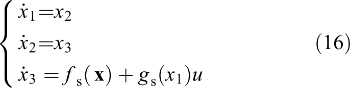
where
Adaptive controller design and stability analysis
Through the aforementioned mathematical model, it can be found that SMA exhibits nonlinear hysteresis and parametric uncertainties subjecting to the temperature and the external load, which makes it quite difficult to predict the thermomechanical behavior accurately. Thus, considering the unmodelled dynamics and the external disturbance, the state equation (16) can be described as
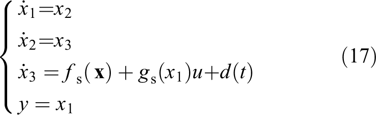
where y is the output displacement and
If we can real-time capture the disturbance
In this subsection, a recursive estimator is firstly designed to estimate both the unmeasured states and the total disturbance. Then, a DC-OFAC scheme is proposed to cope with the tracking control issue. The block diagram of the proposed method is shown in Figure 4.

The block diagram of the SMA actuator control system. SMA: shape memory alloy.
State estimation
State estimation technique is an effective way to estimate both the unmeasured states and the total disturbance. 20 –28 We will turn to an estimator to estimate not only the unmeasured states but also the total disturbance of SMA actuator system in this subsection. The detailed design procedure of the recursive estimator will be presented as follows.
Define
Suppose that
Firstly, the total disturbance

Due to the slow cooling speed, SMA actuator system is a slow system. Therefore, the recursive estimator can be designed as

where
Set

Based on the generalized Lipschitz condition, 30 it can be found that a finite change of the system input will never produce an infinite change of the system output. Similarly, a bounded change of the system output can never be generated by an unbounded change of the system input.
More precisely, an SMA actuator is an energy-consuming physical system. For SMA wires, if the applied temperature exceeds the upper bound
According to Lipschitz condition, there must be a constant

where M2 is a positive constant.
The estimation error equation (20) can be rewritten as

where

Since matrix
Define the Lyapunov function as
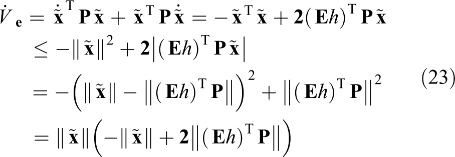
According to equation (21),
Hence, from equation (23),
Controller design
In this subsection, to accomplish the precise position control, a DC-OFAC scheme is proposed on the basis of the BSC theoretical framework. The detailed design procedures are presented as follows.
Step I: The output tracking error is defined as follows

where
The derivative z1 with respect to time is

Let
Denote

where
Equation (25) can be rewritten as follows

Step II: Considering equations (18), (26), and (27), the derivative z2 with respect to time can be calculated by

Define

where
Set

Step III: Considering equations (18) and (29), the derivative z3 with respect to time can be computed by

where
The actual control law u can be constructed as follows
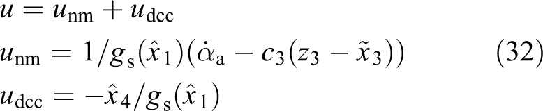
where
Therefore, equation (31) is described as

Let

From equations (22), (27), (30), and (33), the derivative of V with respect to time is given by 27,28

where
If the values of the parameters can be properly selected,

where
The solution of the Lyapunov function is demonstrated as
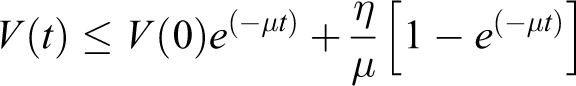
Thus, it is concluded that all the signals in the closed-loop system are convergent, and the controlled system is stable under reasonable conditions.
Experimental results
Parameter identification
To design a controller based on the mechanism model, the first issue is the parameter identification. The unknown model parameters include specific heat capacity (cp), heat convection coefficient (h), martensite start temperature (Ms), martensite finish temperature (Mf), Austenite start temperature (As), Austenite finish temperature (Af), and frictional coefficient (c). Based on the characteristics of SMA material, the identification process consists of two parts.
19
The identification algorithm employs the least square estimator. For the first step, a sinusoidal excitation signal (the frequency is 1/800 Hz and the amplitude scope is 0–0.4 A) is applied to SMA wire. The input and output signals are shown in Figure 5. The identification results are

(a) The lower frequency sinusoidal excitation and (b) response.

(a) The higher frequency sinusoidal excitation and (b) response.
In this research, considering the transient response, the observer bandwidth is chosen as
The comparison results among the system output, NM, and NM-based state estimation (NMSE) are shown in Figure 7(a) to (d). The red “-” is the system output, the blue “- -” is NM response, and the black “-.-.” is NMSE response. Figure 7(a) to (d), respectively, represent the response of some sinusoidal excitation signals at different frequency, which are 1/20, 1/30, 1/50, and 1/100 Hz. From Figure 7, the discrepancy between the NM response and the system output is always larger than the difference between the NMSE. The reasons are obvious: the NM does not completely describe dynamic characteristics of the SMA actuator system, to the contrary, the NMSE can not only involve in the inherent nonlinear dynamics characteristics but also real-time compensate the total disturbance, and improve the model accuracy.

Comparisons results among actual output, NM response, and NMSE response. (a) f = 1/20 Hz, (b) f = 1/30 Hz, (c) f = 1/50 Hz, and (d) f = 1/100 Hz. NM: nominal model.
To quantitatively compare the model accuracy, an important index function, which is the root mean squared error (RMSENMSE/NM), is defined to evaluate the performance of these models:
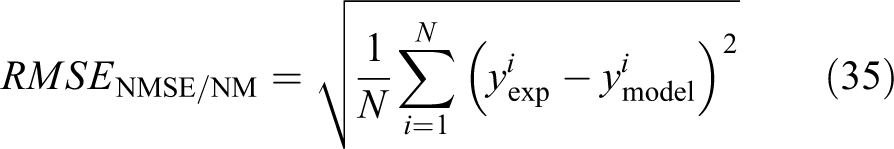
where
The statistical results are also given in Table 1. From the comparisons, the
The index of RMSE.
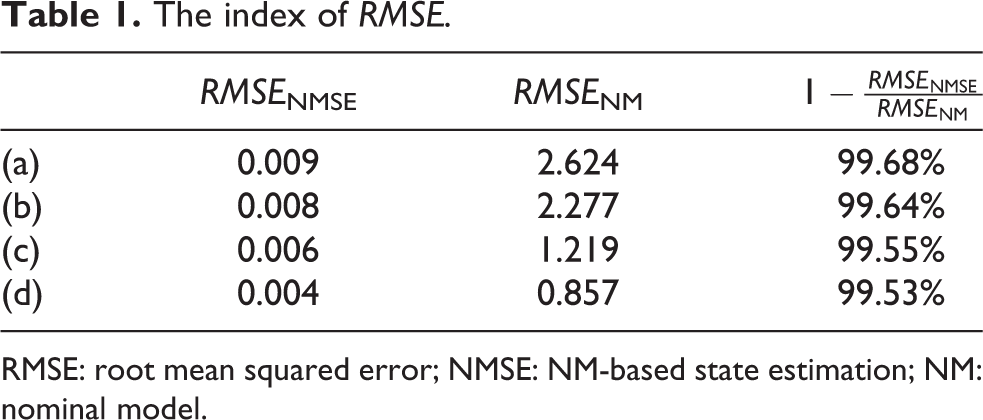
RMSE: root mean squared error; NMSE: NM-based state estimation; NM: nominal model.
Trajectory tracking experiment
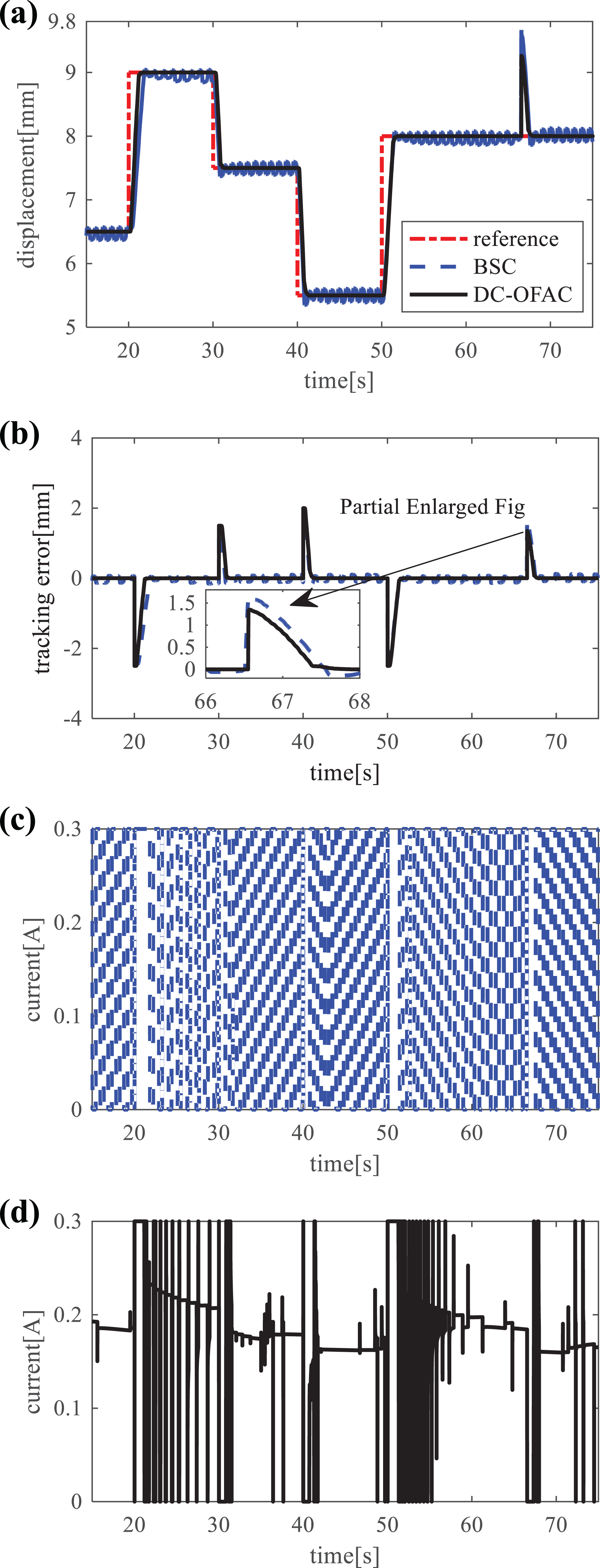
The output tracking experiment is conducted to prove the performance of the proposed DC-OFAC and compared with the traditional BSC. For these two schemes, without loss of generality, the controller parameters c1, c2, c3 should be same and selected to reach a compromise between the tracking error and the smoothness of the control input. For this system, the gain parameters are given in Table 2 and the load is fixed as 500 g. The results are shown in Figure 8(a) to (d). Figure 8(a) shows the output tracking results of these control schemes; Figure 8(b) shows the corresponding tracking errors; Figure 8(c) shows the control input of the BSC; and Figure 8(d) shows the control input of DC-OFAC.

(a–d) Experimental results for trajectory tracking under constant load.
The gain parameters for controller.

The experimental results demonstrate that the proposed method can track various amplitudes of trajectories. However, it is seen that the BSC produces severe fluctuations at 9 and 7.5 mm, and the maximum tracking error is 0.162 mm. Furthermore, based on Figure 8(c), it is clear that the BSC scheme produces poor control input, which varies frequently between the maximum and minimum values. On the contrary, the control input of DC-OFAC scheme exhibits slight oscillation.
To compare the tracking accuracy of these two controllers, the index function is defined as follows

where
The comparison results are presented in Table 3. From the statistical results, it is found that the
The comparison index of error.

To evaluate the power consumption of the above control methods, the following index function is chosen

where
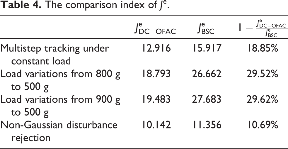
The total energy consumption is given in Table 4. From Table 4, it is found that
The comparison index of
Disturbance rejection experiment
To further test the stability and robustness of these controllers, the tracking experiments under various loads and the regulation experiments under stochastic disturbances (i.e. wind disturbances) will be performed in the following.
Firstly, the system tracks the desired trajectory under the load of 800 g. Then, at the 67.9-s instant, 300 g load is removed from the actuator. The experimental results are shown in Figure 9. The results indicate that the DC-OFAC can track the desired trajectory accurately and ensure the stability and robustness of the control system under various loads. When 300 g load is removed, the DC-OFAC method generates a 0.94 mm error, and the system output returns to the desired trajectory in less than 1.0 s. However, the BSC method fluctuates severely around the desired trajectory. More precisely, various loads lead to 1.083 mm steady error, and it is much higher than DC-OFAC. The reason is that the DC-OFAC is able to adapt to the load variations.

(a–d) Experimental results for trajectory tracking under load variations from 800 g to 500 g.
Furthermore, the system also runs under the external load of 900 g. At the 66.5 s instant, 400 g load is removed from the actuator. The tracking results have been shown in Figure 10. From Figure 10, it can be found that the comparison results of these two controllers are similar to the previous experiment under 800 g load. For DC-OFAC, the tracking error is 1.953 mm, the adjustment time is 2.67 s, and the
(a–d) Experimental results for trajectory tracking under load variations from 900 g to 500 g.
Last, to test the ability of stochastic disturbance rejection, regulation experiments under wind disturbances are presented. A fan is placed at a distance of 50 cm from SMA wire and the wind speed is 3.0 m/s. The equipment is opened in 30 s and closed in 40 s. The results are shown in Figure 11. Due to the time lagging characteristics of temperature, the controlled system has a delayed output response. Figure 11 has demonstrated that the maximum error of DC-OFAC is 0.067 mm, while the BSC is 0.181 mm. After the fan has been closed, the system still has a delayed response. Meanwhile, the maximum tracking error of DC-OFAC is 0.012 mm and the BSC is 0.022 mm. Based on Tables 3 and 4, The

(a–d) Experimental results for stochastic non-Gaussian disturbances rejection.
Conclusion
This article proposed a DC-OFAC scheme to accomplish the precise control of SMA actuator system. A NM-based state estimation technique is developed to achieve the estimation of unmeasured states and the total disturbance. The control scheme relies on the combinations of nominal controller, to deal with the inherent nonlinear dynamic characteristics of the system, and the compensation controller, to deal with the total disturbance. The robust stability of the closed-loop system can be rigorously proved by the analysis of the Lyapunov function. Finally, various experiments for the trajectories tracking, loads variations, and wind disturbances have been conducted in this article. The experimental results have indicated that the proposed control strategy can effectively deal with the disturbance and has a better performance in terms of stability and robustness. In the future, the proposed control strategy will be further applied to the SMA-actuated prosthetic hand.
Footnotes
Declaration of conflicting interests
The author(s) declared no potential conflicts of interest with respect to the research, authorship, and/or publication of this article.
Funding
The author(s) disclosed receipt of the following financial support for the research, authorship, and/or publication of this article: This work was supported in part by the National Natural Science Foundation of China [Grant Nos U1813214, 61903360, 61773369, and 61821005], in part by Self-planned Project of the State Key Laboratory of Robotics [Grant Nos 2019-Z12 and 2020-Z12], in part by China Postdoctoral Science Foundation funded project [Grant Nos 2019M661155 and 2019M661157], and in part by Liaoning Province PHD foundation of China [Grant No. 20180540131].