
Abstract
The design of a high-precision robot assembly system is a great challenge. In this article, a robotic assembly system is developed to assemble two components with six degree-of-freedoms in three-dimensional space. It consists of two manipulators, a structured light camera which is mounted on the end-effector aside component A to measure the pose of component B. Firstly, the features of irregular components are extracted based on U-NET network training with few labeled images. Secondly, an algorithm is proposed to calculate the pose of component B based on the image features and the corresponding three-dimensional coordinates on its ellipse surface. Thirdly, the six errors including two position errors and one orientation error in image space, and one position error and two orientation errors in Cartesian space are computed to control the motions of component A to align with component B. The hybrid visual servoing method is used in the control system. The experimental results verify the effectiveness of the designed system.
Introduction
With the development of technology, the demand for high-precision assembly in industrial manufacturing and space exploration is increasing. 1 –3 Industrial assembly devices are generally divided into two categories. One is the specific translation and rotation mechanism. 4,5 For example, Luo et al. 4 used a linear drive mechanism for precision threading operations. The translation error and rotation error of the platform reached 3 µm and 0.005°, respectively. Yu et al. 5 used the feature constraint relationship between components to control translation and rotation devices completing component assembly simulation. However, the working range of specific translation and rotation mechanisms is small, and its flexibility is low. The other is based on a general manipulator. 6,7 For example, Wang et al. 6 added an elastic displacement device to the manipulator to achieve peg-in-hole assembly, which improved the success rate of each assembly. Meng et al. 7 realized precise robot assembly for large-scale spacecraft components based on computer-aided design models of aircraft components and key geometric features located by ranging sensors and binocular vision. Generally, a manipulator has six degree-of-freedoms (DOFs). Therefore, it is very helpful for manipulator-based assembly systems to realize high-precision assembly with six DOFs in three-dimensional (3D) space.
In the robotic assembly system, the target pose is usually measured with vision-based methods. 8,9 Generally, the point feature, line feature, and circle feature are employed in the pose estimation methods. For example, in Liu et al., 10 the end position of the dispensing needle was obtained through the point feature and then the precision dispensing operation was completed. In Liu et al., 11 line features were used to measure the pose of a long cylindrical component. In Liu and Xu, 12 a fast and effective circle detection algorithm was proposed for target position estimation. However, the above pose estimation methods require two or three cameras placed in different directions. Sun et al. 13 measured the target pose with a camera based on the projection relationship between the circle and the ellipse. But the accuracy of this method relies on the ellipse fitting. Another kind of target pose measurement method with the structured light camera is becoming popular. 14 –16 For example, Kim et al. 14 accurately estimated the surface normal vector of the target based on a structured light camera and then completed the object-grasping task. In Satorres et al., 15 the relative position relationship between the manipulator and the object was obtained through the 3D data in the 3D camera. Litvak et al. 16 assembled randomly distributed components based on the depth camera and convolutional neural network, and the success rate reached 91%. Therefore, pose measurement based on a structured light camera is a better choice.
Visual servoing methods are very popular in many applications including automatic assembly systems. 17,18 They are classified as image-based visual servoing, 19 position-based visual servoing, 20 and hybrid visual servoing method. 21 Xu et al. 19 proposed an image-based visual servoing method, in which point features and line features are used for position control and attitude control, respectively. Image-based visual servoing has certain robustness to camera calibration errors and robot model errors. Through comparative experiments on position-based and image-based visual servoing systems, Peng et al. 20 found that position-based visual servoing has a faster convergence speed. What’s more, some advanced control methods for tracking control of mechanical servo systems help improve convergence speed. For example, Deng and Yao 22 designed a high-performance tracking controller without velocity measurement in electrohydraulic servomechanisms, which achieves asymptotic tracking performance when facing time-invariant modeling uncertainties. Aiming at mechanical servosystems with mismatched uncertainties, Deng and Yao 23 proposed a novel recursive robust integral of the sign of the error control method, which achieves excellent asymptotic tracking performance. Therefore, it is necessary to combine the advantages of image-based visual servoing and position-based visual servoing methods to realize the precision assembly of two components.
The purpose of this article is to achieve precise assembly of irregular components. A robotic assembly system is developed to assemble two components with six DOFs in 3D space, which consists of two manipulators and a structured light camera. Image-space information and 3D space information acquired by structured light cameras are effectively combined to measure the pose of component B. Considering the advantages of image-based and position-based visual servoing methods, this article proposes a hybrid visual servoing method with higher convergence speed and accuracy. The manipulators can control the components of different initial positions and postures for automatic assembly. The main contributions of this paper are as follows: A robotic assembly system with two manipulators is developed to assemble two components with six DOFs in 3D space. The hybrid visual servoing method combining errors in Cartesian space and image space is used in the control system. A feature extraction algorithm for the images of irregular components is proposed, which is based on U-NET network training with few labeled images. The pose of component B is calculated from the image features and the corresponding 3D coordinates on its ellipse surface.
The rest of this article is organized as follows. The first part describes the assembly task and system. Secondly, an image feature extraction and pose measurement method is proposed. Then presents a hybrid visual servoing method to align the two components. The details of the automated assembly process are also introduced. The experiments and results with the proposed assembly method are given. Finally, this article is concluded.
Assembly task and system
Assembly task
The two components to be assembled are shown in Figure 1. They are metal connectors with an outer diameter of about 43 mm, which are divided into component A and component B. As shown in Figure 1(a), the left side is component A and the right side is component B. There are five groove areas on the inner side of component B, as shown in Figure 1(b). The positions and sizes of the grooves are unevenly distributed. Correspondingly, there are five protruding areas on the upper surface of component A, as shown in Figure 1(c).

Components: (a) components A and B, (b) component A and its surface structure, and (c) component B and its surface structure.
When assembling, it is necessary to align the groove area of component B to the protruding area of component A with six DOFs, including 3D position and three-direction angles. Our task is to realize the precise assembly of these two components.
Assembly system
The automated precision assembly system is designed as given in Figure 2. Manipulator 1 is a seven-DOF robot with a clamping device and component A connected to it. A structured light camera is fixed at the end of manipulator 1. Manipulator 2 is a universal robot (UR3) with a gripping device and component B connected to it.

Assembly system configuration.
Manipulator 1 can translate along and rotate around the X, Y, and Z axes to align component A to component B. The poses of manipulator 1 and manipulator 2 can be adjusted to initialize the pose of component B in the structured light camera. The computer can control the entire assembly process including image capture with the camera, image processing, feature extraction, pose estimation, and alignment and insertion of the two components.
The coordinates are established as shown in Figure 2. OR 1 XR 1 YR 1 ZR 1 is the base frame of manipulation 1, OR 2 XR 2 YR 2 ZR 2 is the base frame of manipulation 2, ODXDYDZD is the end-effector frame of manipulation 2, OCXCYCZC is the camera frame, and OFXFYFZF is the end-effector frame of manipulation 1. The camera is carefully adjusted so that the axes of the camera frame are as parallel to the axes of the end-effector frame of manipulation 1 as possible.
Image feature extraction
Elliptic ring region extraction
Figure 3 shows the image of component B captured by the structured light camera. To get the current pose of component B in the camera frame, its inherent features such as ring circles should be extracted. As shown in Figure 3(a), there is noise in the gray image of component B, which leads to the disturbance on the edges.

Image of component B: (a) original image, (b) image with manually marked ring area, and (c) image with segmented ring area. In (b) and (c), the ring area is indicated with red color.
There will be a large error in detecting the ring contour of the component through edge detection and ellipse fitting. Another method is to obtain the ring area via threshold segmentation.
But the gray value of the ring area is not evenly distributed due to the influence of light. Therefore, it is difficult to accurately segment the ring area with threshold segmentation.
Therefore, this article uses data labeling and deep learning methods to solve the problem of inaccurate feature extraction. As shown in Figure 3(b), the elliptical ring area on the surface of component B is marked, the outside of the ring is an ellipse, and the inside is an ellipse containing the edge of the groove. A U-NET network is designed and its structure diagram is shown in Figure 4. It includes a contraction path for capturing semantics and an asymmetrical expansion path for precise positioning. The contracted path part consists of four convolutional layers and pooling layers for down-sampling, and the extended path part consists of four deconvolutional layers and convolutional layers for up-sampling. This U-NET network is trained with the labeled data. Then it is used to segment the ring area from the image of component B. As shown in Figure 3 (c), the elliptical ring area containing the groove information is accurately extracted.

U-NET network structure diagram.
Groove feature extraction
General methods cannot effectively detect the groove features on the ring. Therefore, the inner and outer ellipses are combined to detect the groove feature.
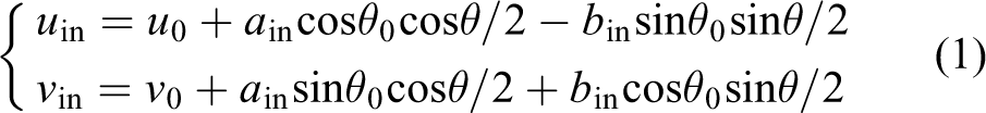
As shown in Figure 5(a), the contour of the elliptical ring area is output by the U-NET network. The two contours containing most edge points of the inner and outer sides are considered as the inner ellipse and the outer ellipse of the ring. Then the least square method is used to fit the inner ellipse parameter equations (1) and outer ellipse parameter equations (2), respectively. The ellipse fitting result is shown in Figure 5(b)

Groove feature extraction process: (a) contours detection, (b) ellipse fitting, (c) groove feature extraction, and (d) image with extracted groove features.
where (u
0, v
0) is the pixel coordinate value of the center point of the ellipse, (u
in, v
in) is the pixel coordinate of the point on the inner ellipse, a
in and b
in are the long and short axis lengths of the inner ellipse,
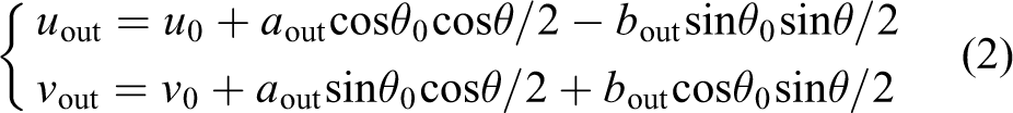
where (uout , vout ) is the pixel coordinate of the point on the outer ellipse and a out and b out are the long and short axis lengths of the outer ellipse.
According to the inner and outer ellipse equations, similar ellipse parameter equations (3) passing through the groove area are obtained

where (ue
, ve
) is the pixel coordinate of the point on the similar ellipse and
The parameter angle θ in the similar ellipse equation (3) is gradually increased to find the continuous point along the similar ellipse where the pixel value is significantly different from the ring area. The corresponding parameter angle set

Feature extraction results via searching along similar ellipses are shown in Figure 5(c). Finally, the average
Automatic assembly
Automatic assembly is divided into three parts, namely the desired image capture stage, the camera alignment stage, and the component insertion stage. The whole assembly process is given in Figure 6.

The program flow chart of the assembly procedure.
The desired image capture stage is mainly to obtain the desired image and the displacement of the manipulator between the alignment and insertion positions via one assembly manually controlled. The desired image features are extracted from the desired image. During the camera alignment stage, the features of component B in image space and Cartesian space are acquired. A hybrid visual servoing control method is designed for precise alignment. In the component insertion stage, component A is translated by displacements D 1 and D 2. Then component A is inserted into component B.
Desired image capture stage
As shown in stage A in Figure 6, manipulator 1 is manually controlled to complete one assembly. Manipulator 1 is translated the given displacement D 1 along the z-axis in its end-effector frame to move component A away from component B. Manipulator 1 is translated along the x-axis in its end-effector frame until the camera can capture the image of component B. The displacement along the x-axis is recorded as D 2. This state is called the camera alignment state.
The images captured in the camera alignment state are considered as the desired image. The elliptical ring area containing the groove of the desired image is extracted by trained U-NET network. The image coordinates

where ad , bd , cd , and ed are the parameters of the fitting plane.
The desired normal vector [ad
, bd
, cd
]
T
is obtained. The desired normal vector is normalized to the desired unit normal vector

The desired posture angle θdx and θdy are calculated with the desired plane unit normal vector by formula (6). Posture angle θm d z is an angle sequence, which contains groove angle information. It is obtained by the above groove feature extraction algorithm

The desired center point image coordinate
In this way, the desired features Pd
, θdx
, and θdy
are acquired in image space, and the desired features
Camera alignment stage
The current image of component B is acquired in real time. According to the above method of feature extraction, the current features
A hybrid visual servoing control system is designed, in which the features from image space and Cartesian space are combined to realize the alignment between component B and camera. The block diagram of the hybrid visual servoing automatic control system is shown in Figure 7.
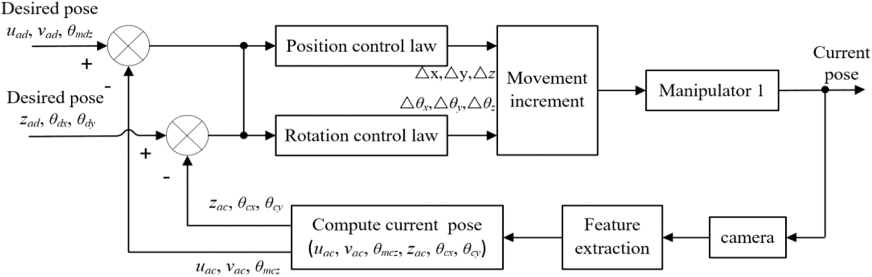
Block diagram of automatic control system.
The pose of the end-effector of manipulator 1 is adjusted in its end-effector frame according to formula (11). The features from image space are used to control translations along the x-axis and y-axis and rotation around the z-axis. The features from Cartesian space are used to control translation of the end-effector along the z-axis and rotations around the x-axis and y-axis

where k
1 and k
2 are coefficients and
As shown in stage B in Figure 6, the camera alignment state is achieved after hybrid visual servoing control. At this point, the errors between the current pose and desired pose approach 0. The displacement between component A and component B along the z-axis in the end-effector frame of manipulator 1 is D 1. The displacement between component A and component B along the x-axis in the end-effector frame of manipulator 1 is D 2.
Component insertion stage
In the component insertion stage, component alignment and component insertion are completed. At first, as shown in stage C in Figure 6, component A is translated the displacement (D 1−d) along the z-axis and the displacement D 2 along the x-axis in the end-effector frame of manipulation 1, where d is a small displacement. After ensuring the safety of assembly, component A is translated the displacement d along the z-axis in the end-effector frame of manipulation 1. Then component A is inserted into component B. The entire assembly is completed precisely and efficiently.
Experiments and results
Experiment system
An experiment system was established according to the scheme given in the “Assembly System” section, as shown in Figure 8. In this experiment system, there were two manipulators including one seven-DOF robotic arm and one six-DOF manipulator. Manipulator 1 had a clamping device and component A connected to it. Manipulator 2 was a UR3 (universal robots company) manipulator with a gripping device and component B connected to it. A structured light camera was fixed at the end of manipulator 1. The structured light camera was LMI Gocator3210 (LMI technologies company) binocular snapshot sensor. The resolution of the camera in the x-axis and y-axis directions is 60–90 µm, the field of view is 71 × 98 mm–100 × 154 mm, and the working distance is 164 mm.

Experiment system.
U-Net network and feature extraction results
The training set for the U-NET network consisted of 60 images with different angles and distances and 600 images generated by data augmentation. Each image was a gray image obtained by the structured light camera in an actual environment. The size of the original images was 1251 × 1925 pixels, which were resized to 512 × 512 pixels when training U-NET network.
The new images of different angles and distances were input into the trained U-NET network for test. The feature extraction experiments with the method described in the “Groove Feature Extraction” section were conducted. The extracted features for the images captured at different angles and distances are shown in Figure 9. Figure 9(a) and (b) are the feature extraction results of the image after rotating around the positive and negative directions of the x-axis, respectively. Figure 9(c) and (d) are the feature extraction results of the image after rotating around the positive and negative directions of the y-axis, respectively. Figure 9(e) and (f) are the feature extraction results of the image after translating along the positive and negative directions of the z-axis, respectively. It can be seen from Figure 9 that the five grooves on the ring area are all accurately extracted.

Feature extraction results of images at different angles and distances: (a) image after rotating around the positive directions of the x-axis, (b) image after rotating around the negative directions of the x-axis, (c) image after rotating around the positive directions of the y-axis, (d) image after rotating around the negative directions of the y-axis, (e) image after translating along the positive directions of the z-axis, and (f) image after translating along the negative directions of the z-axis.
Automatic assembly
Before the assembly experiment, the desired features of component B had been obtained by the method in the “Groove Feature Extraction” and “Desired Image Capture Stage” sections. The coefficient k of the similar ellipse was equal to 0.25. The prior information obtained in desired image capture stage is presented in Table 1.
Prior information.

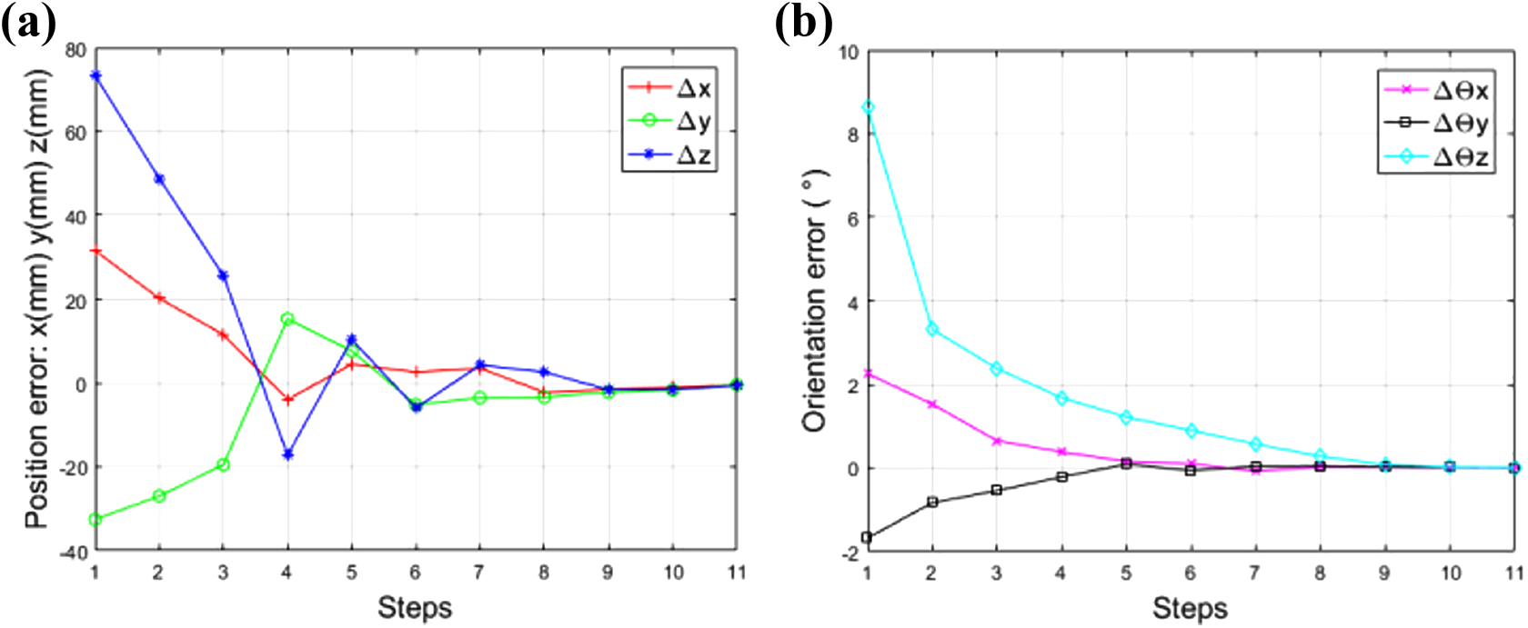
In the assembly experiments, the poses of component A and component B were initialized randomly within a certain range, and the structured light camera obtained the current image of component B in real time. The current features of component B were obtained by the method in the “Groove Feature Extraction” and “Desired Image Capture Stage” sections. The errors between the current features and the desired features were used as the input of hybrid visual servoing system. The coefficients k 1 and k 2 in the hybrid visual servoing system were both set to 0.6. The error curves of component B between the current pose and the desired pose are shown in Figure 10. It can be seen that after about eight steps, the position error and orientation error have approached 0.
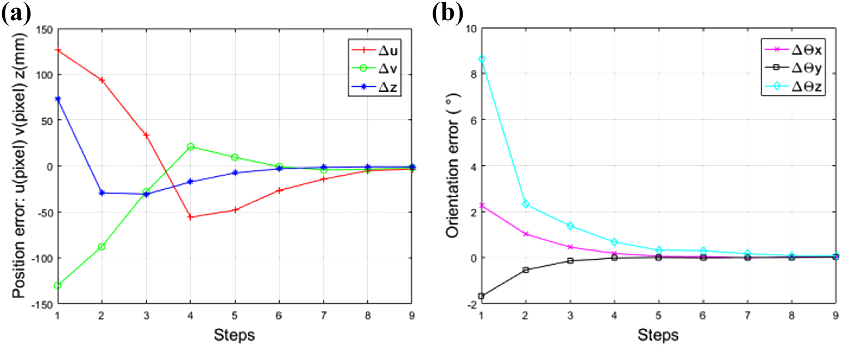
Error curves with the proposed method: (a) position error of component B and (b) orientation error of component A.
The trajectory of component B in image space during the assembly process is shown in Figure 11(a). It can be seen that the center point image coordinates of component B are gradually approached the desired center point image coordinates. The trajectory of component B in Cartesian space during the assembly process is shown in Figure 11(b). It can be seen that the center point 3D coordinates of component B are gradually approached the desired center point 3D coordinates.
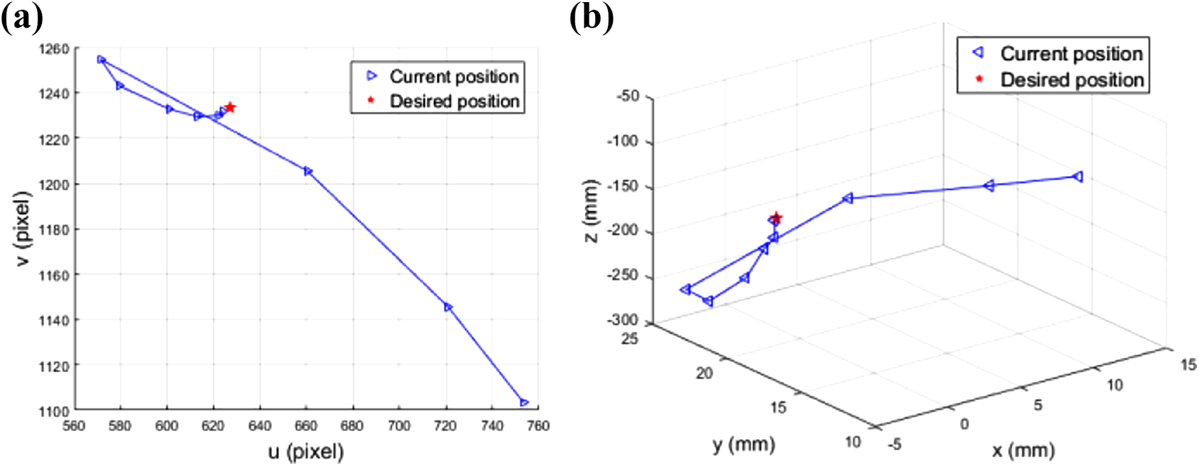
The trajectory of component B in assembly: (a) trajectory in image space and (b) trajectory in Cartesian space.
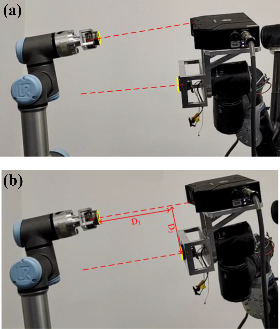
The actual scenes of the desired image capture stage are shown in Figure 12. As shown in Figure 12(a), the manipulator was manually controlled to complete one assembly. Manipulator 1 was translated the given displacement D 1 along the z-axis in its end-effector frame to move component A away from component B. Manipulator 1 was translated along the x-axis in its end-effector frame until the camera could capture the image of component B. The displacement along the x-axis was recorded as D 2.

Desired image capture stage: (a) the direction of movement of the end-effector of the manipulator and (b) the displacement D 1 of the evacuation.
After the desired features had been obtained, we initialized the poses of component A and component B, as shown in Figure 13(a). As shown in Figure 13(b), the camera alignment state was achieved after hybrid visual servoing control.
The camera alignment stage: (a) initial state and (b) camera alignment state.
As shown in Figure 14(a), after component A had moved up D 2, it was aligned with component B. Then component A was translated the displacements (D 1−d) along the z-axis in the end-effector frame of manipulation 1, where d was equal to 3 mm. After ensuring the safety of assembly, component A was translated the displacement d along the z-axis in the end-effector frame of manipulation 1. Then component A was inserted into component B, as shown in Figure 14(b).
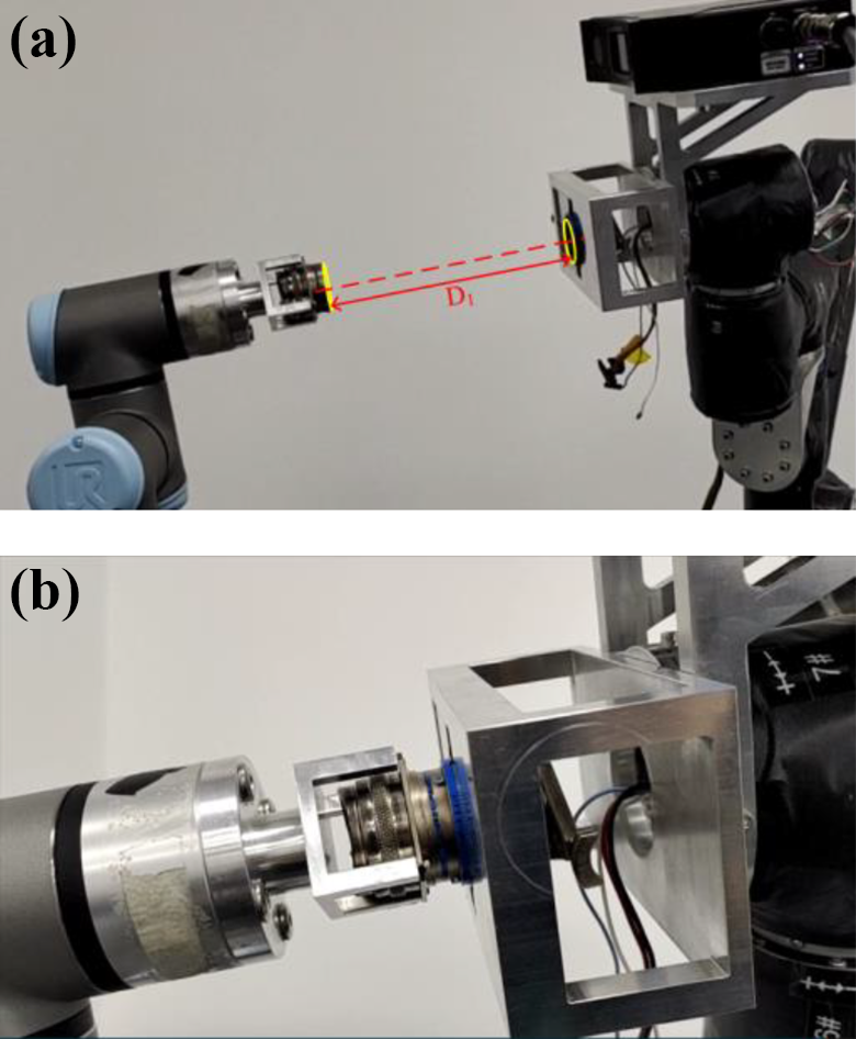
The component insertion stage: (a) translation D 2 and (b) component insertion state.
The total time cost in one assembly was about 18 s: it was as follows, camera alignment 16 s and component insertion 2 s. Fifty assembly experiments were conducted, and all were successful. It can be found the alignment and insertion achieved good results.
Comparative experiments
The position-based method in ref. 20 was selected as the comparative method. The position-based visual servoing control was realized according to formula (9), and the features were all from Cartesian space

where the difference from formula (8) was that xac
, xad
, yac
, and yad
were obtained by directly reading the 3D coordinates of the desired point and current point in the camera, and
The coefficients ka and kb in equation (9) were both set to 0.6. A series of comparative experiments were well conducted. Component A was also well aligned with component B in orientation and position and was successfully inserted into component B to form an assembled component with the method in ref. 20 In one experiment with the comparative method, the error curves of component B between the current pose and the desired pose are shown in Figure 15. It can be seen that after about 10 steps, the position error and orientation error have approached 0. The error curves of the comparative method oscillate more times, and our method has a faster convergence speed.
Error curves with the comparative method: (a) position error of component B and (b) orientation error of component A.
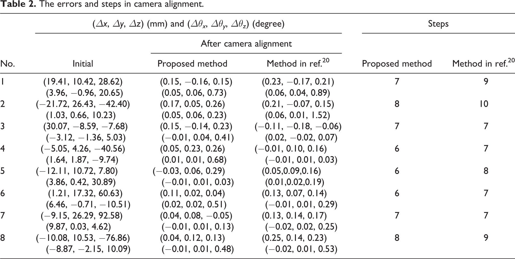
The errors and steps of eight groups of comparative experiments in orientation alignment and position alignment were listed in Table 2. It can be found that the errors of our method are in a smaller range. Because the method in ref. 20 will suddenly have a large error in a certain dimension, our proposed method is more steady.
The errors and steps in camera alignment.
Conclusions
A robotic assembly system with two manipulators is designed to assemble two components with six DOFs in 3D space. A feature extraction algorithm for the images of components is designed with the U-NET network. A hybrid visual servoing method combining the errors in image space and Cartesian space is proposed. Three DOFs are controlled in image space, which are the center’s position on the image plane and the rotation of component B around the z-axis. The other three DOFs are controlled in Cartesian space, which are the depth and the rotations around the x-axis and y-axis.
A series of complete assembly experiments have been conducted in a real environment. The pose error is reduced to a small range in a few steps, and the success rate in 50 assembly experiments is 100%. Subsequently, a series of comparative experiments to compare the proposed method with the method in ref. 20 are well-conducted. The error curves of the method in ref. 20 oscillate more times, and our method has a faster convergence speed. The errors of our method are in a smaller range. Our method can improve the steadiness and efficiency of the alignment process. The alignment process of component A to component B is converged fast and accurately with our method.
In the future, we will pay more attention to more intelligent assembly control methods.
Footnotes
Declaration of conflicting interests
The author(s) declared no potential conflicts of interest with respect to the research, authorship, and/or publication of this article.
Funding
The author(s) disclosed receipt of the following financial support for the research, authorship, and/or publication of this article: This work was supported in part by the National Key Research and Development Program of China under Grant 2018AAA0103004, the National Natural Science Foundation of China under Grant 61873266, the Beijing Municipal Natural Science Foundation under Grant 4212044, and the Science and Technology Program of Beijing Municipal Science and Technology Commission under Grant Z191100008019004.