
Abstract
This article focuses on a novel three-dimensional reconstruction system that maps large archeological caves using data collected by a small unmanned aircraft system with red, green, and blue-depth cameras. Cave sites often contain the best-preserved material in the archeological record. Yet few sites are fully mapped. Large caves environment usually contains complex geometric structures and objects, which must be scanned with long overlapped camera trajectories for better coverage. Due to the error in camera tracking of such scanning, reconstruction results often contain flaws and mismatches. To solve this problem, we propose a framework for surface loop closure, where loops are detected with a compute unified device architecture accelerated point cloud registration algorithm. After a loop is detected, a novel surface loop filtering method is proposed for robust loop optimization. This loop filtering method is robust to different scan patterns and can cope with tracking failure recovery so that there is more flexibility for unmanned aerial vehicles to fly and record data. We run experiments on public data sets and our cave data set for analysis and robustness tests. Experiments show that our system produces improved results on baseline methods.
Introduction
It has long been recognized that cave sites often contain the best-preserved material in the archeological record. Cave archeology has developed its methodologies for mapping and recording sites, yet few sites are mapped to true three-dimensional (3D) models because it is a slow and tedious process for archeologists to record and bookkeep caves. They need to incrementally set up baseline along the cave and then measure the distance from the baseline to cave walls or objects of interest and mark walls or objects in a two-dimensional (2D) map by hand. 1 This slow process has a major negative impact on cultural relic preservation. Typically, archeological teams will visit a site and begin to record it in 1 year, but when they come back to finish data collection, it has been looted, artifacts stolen, architecture destroyed, and the archeological record disturbed. Therefore, archeologists need a faster, more efficient method of surveying and recording the sites.
To accelerate cave mapping, a system that can automate the process needs to be developed. In this system, we first focus on building globally consistent and accurate 3D models using red, green, and blue-depth (RGB-D) data recorded with unmanned aerial vehicles (UAVs). This falls into the research area of visual simultaneous localization and mapping (vSLAM). There are still many challenges in making a well-working vSLAM system that emphasizes surface estimate accuracy. 2,3 Major difficulties are from three sources. First, the camera tracking error accumulation problem can be considered unavoidable due to the incremental nature of any vSLAM system. Second, it is hard to find all the important loops. Intuitively, the more loops in data, the more information can be used to recover precise camera trajectory and the 3D model. But, in practice, when running existing vSLAM systems on data sets with loopy motion at different scales, mismatches can always be found when scanned more than once. This means that loops are not successfully detected, indicating that the recovered camera trajectory is not precise enough. Third, an effective and optimal way of optimizing loop closure in a dense vSLAM system is not yet attempted, due to perhaps the cost of reintegrating dense models.
To get better camera tracking and dense mapping accuracy, researchers tried different ways. In Lefloch et al., 4 curvature information was added into the frame-to-model iterative closest point (ICP). To detect those loops, most vSLAM systems 5 –7 use bag of words (BoW), 8 but it is well known that it is not very reliable under lighting conditions or viewing angle changes. Since the BoW only matches sparse features from images but cannot fully utilize all camera observation data and spatial information. On the other hand, vSLAM systems tend to add the loops very conservatively to reduce the severe influence of the false loops, thus many important loops may not be connected. Even after loops are successfully detected, there is still another problem in the dense vSLAM system: how to correct reconstructed surface optimally. Since most dense vSLAM systems 9,6,10 use a frame-to-model fusion process, which makes it difficult to quantify, isolate, and remove the influence of past camera data, and it is also computational expensive for a full camera data sequence refusion. Whelan et al. 10 suggested forming a deformation graph across the reconstructed dense model to deform its surface to connect the loop. When the loop area is large, the model may not be deformed optimally, since past camera observations are not reused to manipulate the 3D model. They assumed that the scenes are elastic, but in reality, they are mostly rigid.
Motivated by the fact that humans can notice mismatches in 3D models very easily by looking at the spatial displacement of surfaces. We propose to resolve mismatches directly by closing surface loops to get a consistent 3D model and a precise camera trajectory estimate in the vSLAM system. After surface loops are detected, instead of optimizing surface directly to propagate correction introduced by surface loop, in this article, the surface loop correction is done through sparse feature bundle adjustment (BA), so that all the past camera poses can be corrected based on their observations. By running extensive experiments on different data sets, we observed that combining sparse features with surface loop closure can produce better results. Not only 3D models get improved, but also camera trajectories estimate becomes more accurate. This is because our framework can detect loops in the dense surface domain and optimize loops in the sparse feature domain. Note that our framework can detect surface loops, yet other means of detecting loops can still be utilized.
In the following, we summarize the key contributions of our method: We propose a novel 3D reconstruction system that corrects surface loops with sparse feature-based BA. We demonstrate that this novel system can give much-improved camera tracking and dense modeling results. We propose a fast 3D surface-based loop detection method, which is based on a new compute unified device architecture (CUDA)-accelerated point cloud registration algorithm. Experiments show that it is fast and accurate. We propose a novel objective function for surface loop filtering with a sparse feature-based optimization graph. This graph is more robust to different scan patterns and can cope with tracking failure and recovery so that there is more flexibility for UAVs to fly and record data. In addition to the flexibility, experiments show that it performs better than state-of-art methods when only a limited number of loops are detected.
Related work
Related work in visual SLAM
Visual SLAM has been studied actively by researchers from different fields, such as robotics, computer vision, and computer graphics. They solve this problem with their emphases and preferences, which lead to diverse visual SLAM systems. Sparse feature-based SLAM systems are well developed because sparse features can be used to downsample data from sensor reading (e.g. images) to sparse data representation as image keypoints and feature vectors, which means less computation since data from different frames are matched solely based on feature vectors of their keypoints. Extended Kalman filter or particle filter-based filtering approaches 11,12 can take keypoints as visual landmarks and solve vSLAM as a data filtering process. A drawback of this approach is that the filter cannot be reoptimized again based on all previous data. Then, maximum a posteriori (MAP)-based approaches are used to optimize all observed camera data in a batch setting, 7 which utilizes BA from Structure from Motion, 13,14 and to get better accuracy. 7 To run BA for loop closure, the loops need to be detected. In the sparse image feature setting, BoW-based loop closure is widely used. But it gives a high portion of false loops, which can severely degrade the performance of a vSLAM system, so a very strict loop filtering is often used, 7 where many loops are rejected. This causes a big problem when there are many loopy motions in camera movement.
Another line of vSLAM research focuses on surface reconstruction. With the parallel processing power of graphics processing unit (GPU), Newcombee et al. proposed KinectFusion 9 which performs real-time dense 3D camera tracking and model fusion. It has a volumetric scene representation, which can be rendered to a depth map at a given camera pose. Tacking is done through a frame-to-model projective ICP, which is parallelized on GPU for real-time performance. Finally, new camera data are fused into the volumetric model using a running average. KinectFusion can be considered of fusing very local loops together using the model it maintains as a proxy, but it does not close large loops. To close large loops, it is important to detect loops and find relative poses between loop areas. In BoW, image keypoints and features are used for both loop detection and relative pose generation, but in dense 3D systems, there is no such comparably reliable point cloud feature. Whelan et al. use BoW in a dense SLAM system called Kintinuous, 6 which is an extended KinectFusion system. Later, to better solve the loop detection and optimization problem, ElasticFusion 10 proposed to use ICP to find relative poses of potential loops, which are proposed by two sources of information: spatial prior and appearance-based place recognition. Our work shares similarities with Whelan et al., 10 but we propose a different approach and underlying algorithms, instead of using projective ICP, which highly depends on initialization. We propose a GPU-based global point cloud registration method to detect loops with other prior information from sparse feature alignment. After surface loop was detected, in Kintinous, a pose graph of keyframes was utilized, while the authors mentioned that mesh deformation was required to get smooth 3D models, which indicates loop correction is not done optimally. In ElasticFusion, the pose graph is replaced by a deformation graph distributed inside the dense model. This deformation graph does not have a backing physical meaning, because most of the scenes scanned are not elastic. In our framework, we utilize BA to have a MAP correction of all past keyframes, which is theoretically optimal. BundleFusion 14 used BA to optimize loops, but they do not close surface loops. Instead, they close sparse feature loops and only use the dense surface for feature correspondence search and tracking.
Related work in loop detection
Handcrafted image features are widely used in loop closure detection. Cummins and Newman propose Fast appearance based mapping (FAB-MAP), 15 which is a probabilistic framework for navigation using only appearance data. Angeli et al. propose an online method to run visual word-based loop detection within the framework of an online image retrieval task. 16,17 Williams et al. 18 describe a relocalization module, in which relocalization is performed by a randomized lists classifier to establish landmark correspondences in the image and then random sample consensus (RANSAC) to determine the pose robustly from these correspondences. Another widely used approach, distributed BoW, 8 is proposed by Galvez-Lopez and Tardos, which use BoW for visual place recognition with features from accelerated segment test (FAST) keypoint detector and Binary Robust Independent Elementary Features (BRIEF) with a binary vocabulary tree.
There are new attempts to make further improvements, including modifications on the BoW 19 –21 and detection by image sequences. 22 –24 There are also explorations to detect loops with more than a single image. 25,23,26 Some works try to improve loop detection precision with loop verification threshold learning in RANSAC based on geometric. 27 Some others try to make improvements for special environment. 28,29
After, convolutional neural networks (CNNs) dominate computer vision-related tasks6. There are research works that try to build loop detection methods with CNN features for similarity search. 30 –32,26 Another line of work builds special CNN architectures for loop detection problem. 33,33
Overview of the proposed system
The method proposed aims at producing accurate 3D models by detecting and optimizing surface loops in sparse feature-based visual SLAM systems. By adding surface loop closure into a vSLAM system, we can get globally consistent and optimal 3D models. With our proposed algorithms, we build a novel system with five components: (1) tracking, (2) surface model fusion, (3) fast surface loop detection, (4) surface loop filtering, and (5) loop optimization.
Tracking
We employ the tracking part from ORB-SLAM2, 7 which is a very wellimplemented sparse feature-based SLAM system. Inside this tracking module, the Oriented FAST and Rotated BRIEF (ORB) features are extracted for keypoint matching. Then frames are tracked against keyframes with motion estimate and then refined with a local sparse map. Keyframes are generated when tracking is weak, or the local BA thread is free. Local BA is used to correct the reprojection error of feature correspondences among covisible keyframes in a background thread. This tracking module provides camera poses for each frame and a covisibility graph across keyframes.
Surface model fusion
We fuse surface models on a GPU using surfels as a map representation similar to the literatures.
34,10
Each surfel has a position
Fast surface loop detection
The proposed surface loop detection is done by point cloud registration on surface fragments. To detect surface loops effectively, the covisibility graph from tracking is utilized to prefilter covisible surface fragment pairs that are already connected. Thus, a majority of unnecessary computation can be avoided. To detect surface loops efficiently, we propose using CUDA to accelerate point cloud registration. Details of this acceleration are described in the next section.
Surface loop filtering
After loop candidates are detected, they need to go through a novel loop verification algorithm, so that false loops would not diverge the subsequent optimization process. This is in the surface loop filtering section.
Loop optimization
After surface loops are detected and verified, the loop pairs are used to connect pose graph vertices and also trigger more image loop detection, which again uses spatial prior and ORB feature matching. Then, the pose graph is optimized to give a coarse pose correction and then a full BA is performed to get MAP optimally fine-tuned camera trajectory estimate. Details are in the loop optimization section.
Global Point Cloud Registration on GPU


Fast surface loop detection
To formulate surface loop detection formally, we denote a surface fragment as a set of points
As shown in Algorithm 1, point clouds are downsampled to the resolution of the typical precision of RGB-D sensors to reduce unnecessary computation. Fast point feature histograms (FPFH) features are extracted for each point in

where lc
is the cell edge length of the NN 3D grid. The
Surface loop detection evaluation
We run experiments to compare speed, recall, and precision performance with the baseline method: point cloud registration part of Choi-Zhou-Koltun (CZK) on redwood pairwise registration evaluation data set by Choi et al. We report results in Table 1. Recall and precision for CZK are from reports of article authors, but speed is measured on our machine. We use the same hyper-parameter values as in the published code of CZK: 0.05 m as point cloud downsampling leaf size, 0.1 m as normal estimate radius, 0.25 m as FPFH feature estimate radius, 4,000000 as hypotheses count, and 0.075 m as maximum point correspondence distance. We use an Intel i7-6850 K (https://ark.intel.com/content/www/us/en/ark/products/94188/intel-core-i7-6850k-processor-15m-cache-up-to-3-80-ghz.html) clocked at 3.6 GHz and an NVIDIA Titan X Pascal (https://www.nvidia.com/en-us/geforce/products/10series/titan-x-pascal/) for our evaluation.
Performance evaluation of different point cloud registration methods.
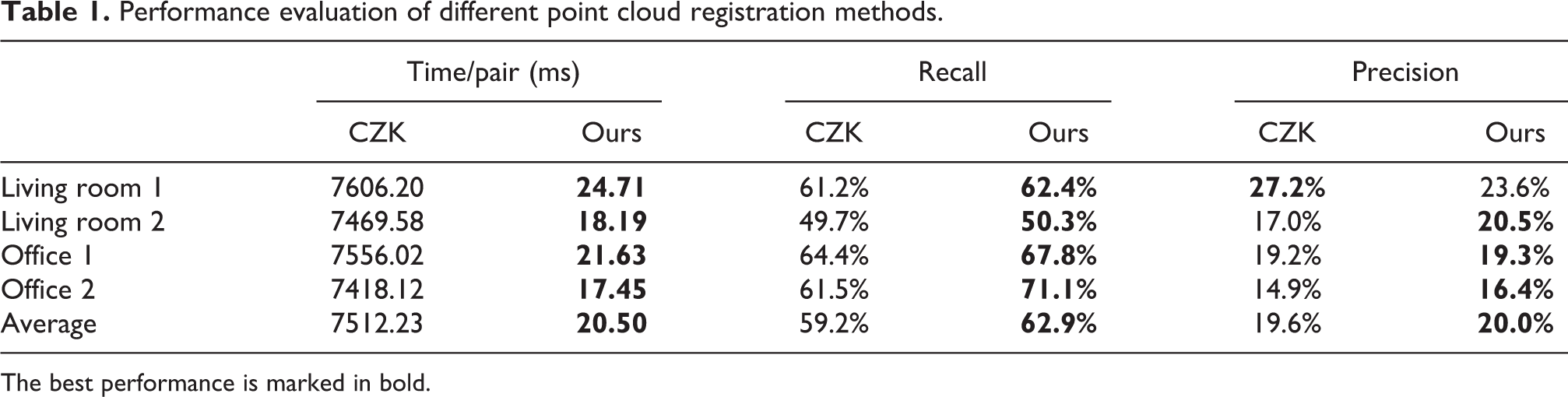
The best performance is marked in bold.
Observations
Our global point cloud registration can finish in around 20 ms, which is around 366 times faster than CZK as in Table 1. With this speed, it can run at 50 Hz, which means we can process more loop candidates. Our recall performance is not compromised for speed. Instead, it is even better than all these two methods. From Table 1, the low precision is an issue that needs to be solved, so an effective loop filtering method is proposed and described in the following section.
Surface loop filtering
The results out of the surface loop detection algorithm in the previous section have a low precision problem. Choi et al. proposed to use a line process-based optimization to solve it. 35 But that method requires scanning to be tracked fully successfully from the beginning to the end, and each surface fragment cannot be empty. However, during a long scanning session, it is almost impossible to guarantee that RGB-D cameras always have surfaces observed within their effective range. A failure to maintain that will lead to an empty surface fragment. Thus, the graph vertices are potentially divided into more than one subgraph, which leads to erroneous optimization results. A similar problem will occur when tracking failure is present in the tracking part, which will break the optimization graph as well. To address this problem, we propose to minimize (2) instead, which has a supporting optimization graph that is always fully connected whenever sparse features are matched from either tracking or failure recovery

where

The objective function optimizes over a set of point clouds
In eq. (3),

Then
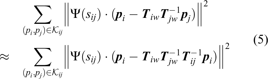
To accelerate computation of eq. (5), we follow an approximation proposed in Choi et al.
35
The local parameterization of
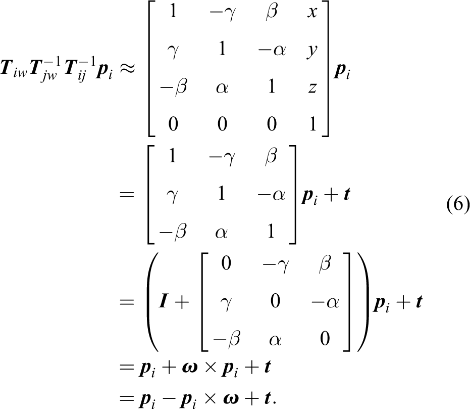

where
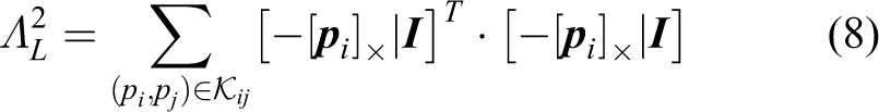
where
where

After optimizing eq. (2), keyframes i and j should be connected as a loop if the optimized value of switch variable
Surface loop filtering evaluation
Experiment design
To understand the performance of the proposed method and compare it with CZK, we run experiments on the augmented ICL-NUIM data set for loop filtering evaluation. In the experiments, RGB-D frames are first fused into scene fragments with the implementation provided by CZK. Point cloud registration results from CZK are used as loop detections. Two sets of experiments are conducted: One takes all the successful point cloud registration results as loop detections, denoted as All pairs in Table 2. Another set of experiments only consider point cloud pairs that are not covisible in ORB-SLAM2 tracking results as loop detections, which is denoted as Only non-covisible pairs in Table 2. A pair of scene fragments is covisible if there are any covisible frames between two sets of frames contained in the two scene fragments. This only non-covisible set of loops is more close to practical use cases because the covisible pairs can be ignored for computational speed consideration and have been well connected in SLAM systems, already.
Performance evaluation of different loop filtering methods reported in percentage.

The best performance is marked in bold.
Observations
When only non-covisible pairs are presented, the proposed method outperforms CZK in average precision, while recall is only 2% less. For office 1 sequence, our method gives better results in both precision and recall, while CZK output only 62.5% precision. Such a low precision usually causes serious problems because too many false loops go in the loop optimization step. For the other three sequences, our method gives competitive results. When all pairs are considered, CZK performs so well that our method is closely under it. The difference is mainly in recall, while precision difference is very small. Considering precision is more important than recall for loop optimization, we would like to note that this minor difference rarely impacts on the final loop optimization result.
In addition to the cases where our method performs better, note that our method is less strict to use in practical scenarios, especially on a fast-moving UAV platform. Because our method does not require maintaining RGB-D cameras facing surfaces all the time, which is required by CZK. This requirement difference is inherently implied by underlying optimization pose graphs.
Loop optimization
After a surface loop passing verification, map optimization is followed to reduce mismatches and errors. We employ pose graph optimization and new data association and finally run a full BA to get a MAP-based optimization to correct the camera trajectory estimate and thus improve the 3D model.
When a surface loop pair
Finally, a full BA is performed for all the keyframes and observed map points by optimizing the following equation

Evaluation of the full 3D reconstruction system
In addition to experiments in the fast surface loop detection section and surface loop filtering section, extensive experiments are performed to evaluate the proposed full 3D reconstruction system on multiple data sets: our Maya cave data set, augmented Imperial College London and National University of Ireland Maynooth (ICL-NUIM), 35 Technical University of Munich (TUM) RGB-D data set, 39 Scene understanding 3D (SUN3D) data set, 40 and some other public data sequences. Comparisons are made with other online and offline methods. There are many SLAM algorithms and implementations. Here, we choose baseline methods in a way that they can best show the characteristics of our proposed system: We choose ORB-SLAM2 7 since we use the tracking part of it and offline method CZK 35 because our loop filtering part is inspired by it. We denote the tracking part of ORB-SLAM2 as tracking and full ORB-SLAM2 as ORB-SLAM2 in all experiments. Results of baseline methods are from original articles or their authors when available.
Maya cave data set
The Maya cave data set is a data set collected by a team of archeologists using an RGB-D sensor Kinect V1 in Maya caves at Las Cuevas, Belize. Light-emitting diode lights are used to light up the environment as in Figure 1. In this data set, caves are scanned with a loopy motion for more loop optimization.

A part of a cave.
Experiment design and baseline methods
We evaluate modules of both tracking and loop closure from different approaches on the data we collected. For RGB-D data, there are two major different camera tracking methods, which are sparse feature-based and dense frame-to-model approaches. We choose the ORB-SLAM2 as the implementation for the sparse feature tracking and the ElasticFusion for the dense frame-to-model implementation. In experiments for tracking, both implementations have their loop closure disabled so that the difference can reflect tracking performance. In tracking of ElasticFusion, there is one important parameter that controls the weight of RGB in tracking. We use the default 10 for RGB-D tracking, and a number greater than 100 can disable RGB completely so that the tracking is totally based on the depth. For loop closure, there are three different types. ElasticFusion is using Ferns-ICP-based approach. ORB-SLAM2 utilized BoW. Our point cloud registration-based surface loop detection approach is the third type compared.
Observations on tracking
From Figures 2 to 5, we can see that RGB-D tracking of ElasticFusion does not work well on cave data, especially compared with when it uses depth only. We think this is due to the moving light source. RGB-D tracking calculates a transformation matrix partially by minimizing the intensity difference of two aligned images, which assumes the lighting condition of scenes is static. The ElasticFusion depth tracking working quite well in most sequences excepts on the chamber-floor-walking data sequence. We can see in Figure 2(b) that half of the floor data get rotated around 90° clockwise. It is almost impossible for a dense direct tracking to recover from the error; due to that, there are no strong correspondences. The tracking of ORB-SLAM2 performed very well in all the data sequences, and it provides the possibility of globally optimize the map. The robustness of feature-based tracking implemented by ORB-SLAM2 is the reason that we use it as our tracking module.
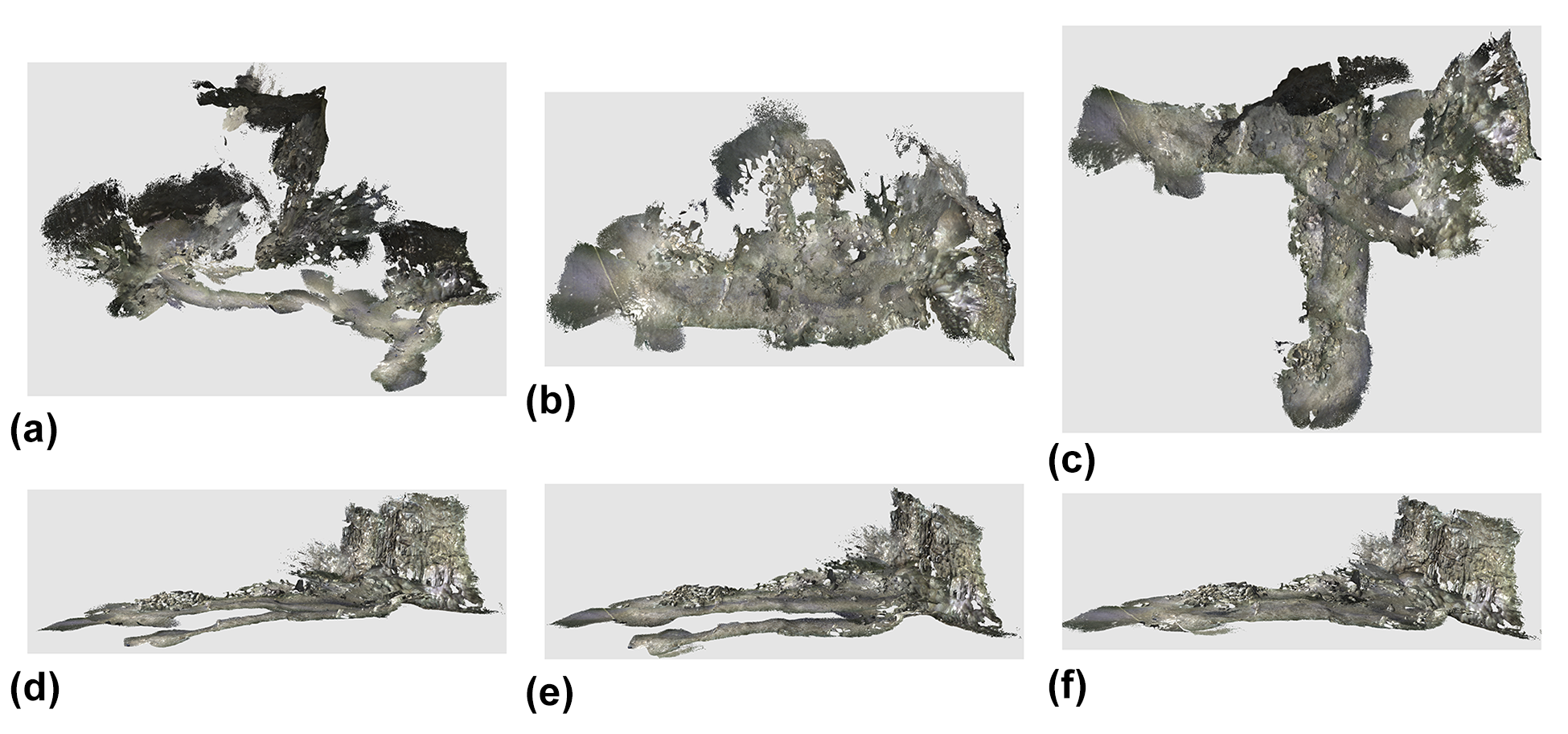
Results on the chamber-floor-walking sequence. (a) ElasticFusion RGB-D tracking, (b) ElasticFusion Depth tracking, (c) ElasticFusion full, (d) ORB-SLAM2 tracking, (e) ORB-SLAM2 full, and (f) Ours. RGB-D: red, green, and blue-depth; ORB: oriented FAST and rotated BRIEF; SLAM: simultaneous localization and mapping; FAST: features from accelerated segment test; BRIEF: binary robust independent elementary features.

Results on the chamber-entrance data sequence. (a) ElasticFusion RGB-D tracking, (b) ElasticFusion Depth tracking, (c) ElasticFusion full, (d) ORB-SLAM2 tracking ,(e) ORB-SLAM2 full, and (f) Ours. RGB-D: red, green, and blue-depth; ORB: oriented FAST and rotated BRIEF; SLAM: simultaneous localization and mapping; FAST: features from accelerated segment test; BRIEF: binary robust independent elementary features.

Results on the chamber-alcove data sequence. (a) ElasticFusion RGB-D tracking, (b) ElasticFusion Depth tracking, (c) ElasticFusion full, (d) ORB-SLAM2 tracking, (e) ORB-SLAM2 full, and (f) Ours. RGB-D: red, green, and blue-depth; ORB: oriented FAST and rotated BRIEF; SLAM: simultaneous localization and mapping; FAST: features from accelerated segment test; BRIEF: binary robust independent elementary features.

Results on the chamber-cave-floor data sequence. (a) ElasticFusion RGB-D tracking, (b) ElasticFusion Depth tracking, (c) ElasticFusion full, (d) ORB-SLAM2 tracking, (e) ORB-SLAM2 full, and (f) Ours. RGB-D: red, green, and blue-depth; ORB: oriented FAST and rotated BRIEF; SLAM: simultaneous localization and mapping; FAST: features from accelerated segment test; BRIEF: binary robust independent elementary features.
Observations on loop detection and optimization
When we compare the performance of loop closure, our surface-focused method performs the best. It connects important loops in all four sequences. The difficult data are the chamber-floor-walking one, as shown in Figure 2. Neither ElasticFusion nor ORB-SLAM2 tracks the camera trajectory correctly. Even after their loop closure, mismatches are still significant. Our method shows its robustness by reconstructing consistent 3D models on all data.
Augmented ICL-NUIM data set
We use the augmented ICL-NUIM data set 35 to quantitatively analyze the performance of our system. This data set is a synthetic data set with ground truth surface models and camera trajectories. It has two indoor scenes: a living room and an office, and four RGB-D sequences, two sequences for each scene.
Experiment design
Evaluation metrics are camera trajectory translation root mean square error (RMSE) described by Handa et al. and the mean distance of the reconstructed surfaces to the ground truth surfaces in the same way as Whelan et al. We report them separately in Tables 3 and 4. Since different systems use different ways to fuse 3D models, for a fair comparison, we fuse 3D models using ElasticFusion using the same parameters with a camera trajectory estimate from each system. We use truncating depth distance of 4 m and
Mean surface reconstruction error (in m) on augmented ICL-NUIM sequences.
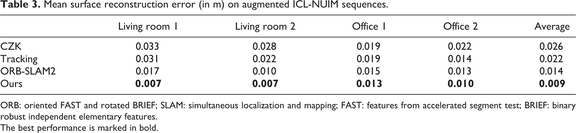
ORB: oriented FAST and rotated BRIEF; SLAM: simultaneous localization and mapping; FAST: features from accelerated segment test; BRIEF: binary robust independent elementary features.
The best performance is marked in bold.
RMSE (in meters) of estimated camera trajectories.

RMSE: root mean square error; ORB: oriented FAST and rotated BRIEF; SLAM: simultaneous localization and mapping; FAST: features from accelerated segment test; BRIEF: binary robust independent elementary features.
The best performance is marked in bold.
Observations
From Tables 3 and 4, our system can give best results on all data sequence in terms of both trajectory and surface estimation accuracy. To give a more informative comparison, we report an error map of the reconstructed model in Figure 6 on Living room 1 data sequence. We can see our results that have the lowest error across the whole model. Our method performs better because more loops get detected for improving the final loop optimization results. In ORB-SLAM2, the loop detector has trouble detecting some important loops because its consistency check can hardly be satisfied due to very local view overlappings. On the other hand, our surface loop detector does not have this problem. Compared to CZK, the performance gain comes from the advantage of sparse feature-based BA optimization, which can produce MAP results, thus more accurate camera trajectories and better reconstructed 3D models.

Distance error map of reconstructed models from different methods against ground truth on living room 1 data sequence. (a) CZK, (b) tracking, (c) ORB-SLAM2, and (d) Ours. ORB: oriented FAST and rotated BRIEF; SLAM: simultaneous localization and mapping; FAST: features from accelerated segment test; BRIEF: binary robust independent elementary features.
SUN3D data set
The SUN3D data set 40 is a large-scale RGB-D database that captures many places. It contains many data sequences. And there are eight sequences (http://sun3d.cs.princeton.edu/listNow.html) that are labeled with object annotations and widely used for evaluating SLAM and 3D reconstruction systems. Since there is no ground truth available, we follow this practice and run experiments on these sequences. We show qualitative results in the form of screenshots of reconstructed 3D models in Figure 7.

Results on sequences of the SUN3D data set. The left column shows the results of the tracking part. The right column shows the results after our loop optimization. We highlight the mismatches in tracking results so that differences are easier compared.
For the sequences in Figure 7, we highlight the mismatches in tracking results so that readers can better compare them with our results. For sequences harvard_c5, harvard_c6, and harvard_c8, there are no loops detected on top of tracking. So we do not include screenshots for them.
Observations
SUN3D data sequences are scanned with very loopy motion in some areas but only once for some other scene parts, thus is considered more difficult. Even though our method does not produce perfect reconstructed 3D models, it dramatically removed some significant mismatches. Also, our results are on par or better than other methods. Interested readers may compare with the results of CZK on this webpage (http://redwood-data.org/indoor/models.html).
TUM RGB-D data set
The TUM data set 39 is an RGB-D data set that is commonly used to evaluate SLAM systems. This data set has 39 RGB-D sequences recorded in office and industrial environments with a large variety of camera motions and scenes. Along with RGB-D sequences, ground truth camera trajectories that are recorded with a motion capture system are also available. Following common practice, we run experiments only on sequences that are commonly used for SLAM evaluation. 7
Observations
From the results listed in Table 5, it shows that for data sequence fr1/desk, fr1/room, fr2/desk, and fr3/office, our method makes improvement on tracking and achieves competitive results comparing full ORB-SLAM2. Among these sequences, fr1/room has high absolute trajectory error (ATE) in tracking, and our surface loop significantly reduced the error. For the small performance difference, we think that it is due to the implementation difference of the tracking part and that the difference only has only marginal effects on reconstructed 3D models when ATE error is less than 0.02 as presented in Table 4 and Figure 6. For sequences fr1/desk2 and fr2/xyz, the tracking has provided good enough results that most of the frames are connected in the covisibility graph such that there are no loops to be detected. The sequence fr3/nst is a scan of a flat wall with rich texture but no geometry changes, so our method cannot detect surface loops in it; thus, no improvement is made. The TUM data set indicates that even though our method is designed for larger-scale environments with rich geometry changes, it can produce competitive results for some small-scale environments.
TUM RGB-D data set comparison ATE (m).
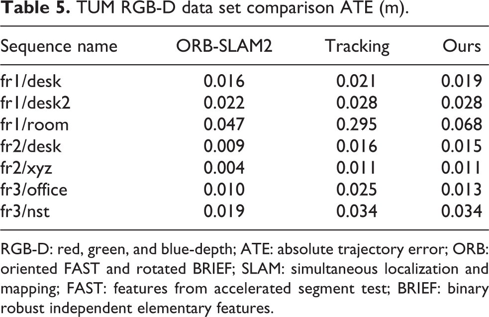
RGB-D: red, green, and blue-depth; ATE: absolute trajectory error; ORB: oriented FAST and rotated BRIEF; SLAM: simultaneous localization and mapping; FAST: features from accelerated segment test; BRIEF: binary robust independent elementary features.
Other public real-world scenes
We also run experiments on public real-world data sequences for qualitative analysis and a robustness test. We run our system on Copyroom and Lounge data sequences from Zhou et al. and DysonLab data set from Whelan et al. We report our qualitative results in Figure 8. Since there are no ground truth models available, we only report screenshots of reconstructed models from our system. Due to space limitations, we do not include the results of other systems. Interested readers can refer to the authors’ release. Visually, our system produces results at least matching the state-of-the-art methods.

Reconstructed models of real-world scenes. (a) Copyroom, (b) Lounge, and (c) DysonLab.
Conclusion
This article presents a novel 3D reconstruction system that maps both large archeological caves and general indoor environments with RGB-D cameras. The proposed system produces accurate 3D models by detecting and optimizing surface loops in sparse feature-based visual SLAM systems. By adding surface loop closure into a vSLAM system, globally consistent and optimal 3D models are generated accurately. The proposed system consists of five components: (1) sparse feature-based camera tracking from ORB-SLAM2, (2) surface model fusion powered by Surfels, (3) a novel fast surface loop detection algorithm, (4) a novel surface loop filtering method, and (5) loop optimization based on sparse feature-based BA.
For fast surface loop detection, we propose and implement a CUDA-based global point cloud registration algorithm that is parallelized to run on GPUs for faster RANSAC hypotheses testing. The proposed point cloud registration algorithm can finish in around 20 ms on NVIDIA Titan X Pascal without any precision and recall performance losses. The accelerated computational speed makes it possible to be used as a loop detection method.
In the surface loop filtering component part, a novel objective function is proposed to remove false-positive loops from entering the loop optimization step. The proposed objective function formulates a least-square pose graph with a BA term as the supporting backbone graph and robust least square terms with switchable constraints for surface loop detections. Due to the inherent difference in underlying optimization pose graphs, compared with its closely related work: CZK, our method is less strict to use in practical scenarios, especially on a fast-moving UAV platform. Because our method does not require maintaining RGB-D cameras facing surfaces all the time, but CZK requires it. In addition to the flexibility, the proposed method is benchmarked against CZK on the augmented ICL-NUIM data set in terms of filtered loop detection precision and recall. Experiments show that the proposed method performs better (with
Moreover, experiments are conducted to evaluate the performance of the full novel system on multiple data sets, including our Maya cave data set, augmented ICL-NUIM, TUM RGB-D data set, SUN3D data set, and some other public data sequences. The results are evaluated with ATE or trajectory RMSE when ground truth camera trajectories are available, surface reconstruction error when ground truth 3D models are accessible, and visual comparisons when no ground truth is available. The results show that sparse feature-based camera tracking performs the best in cave environments. The results also show that the proposed system produces the most reliable and accurate 3D reconstruction performance when surface loops are detected, filtered, and optimized on a sparse feature-based objective function. Other than in cave environments, experiments on other data sets show that the proposed system produces results on-par or better than baseline methods.
Footnotes
Declaration of conflicting interests
The author(s) declared no potential conflicts of interest with respect to the research, authorship, and/or publication of this article.
Funding
The author(s) disclosed receipt of the following financial support for the research, authorship, and/or publication of this article: This work was supported by CITRIS Seed Grant entitled “Drones for Cave Archeology and 3D Mapping”.