
Abstract
Today’s technology allows people to remotely control and monitor many systems. In these technological systems, robots or unmanned vehicles are generally used, which are controlled remotely without human interaction. Unmanned aerial vehicle (UAV), which does not have a pilot on it, is one of the unmanned vehicles capable of flying either remotely or automatically. UAVs are among the systems that are used in many fields for military, civil, and academic purposes and are constantly developing in parallel with the advancement of technology. One of the biggest problems of UAVs that are effectively used in many areas is undoubtedly flight times. To overcome this situation, charging stations are used and allow the UAV batteries to be charged without human intervention. In this article, a review study about the charging stations developed for charging batteries used in UAVs has been made. In this study, the findings obtained as a result of literature research on charging stations were analyzed and the performances of charging stations were compared. The main purpose of this review study is to guide people who will develop a charging station for rotary-wing UAVs by providing a preliminary research opportunity and to help choose one of the wired or wireless charging stations according to the needs in the applications to be developed.
Introduction
Technological studies bring many innovations to people. Every day a new technology emerges and is made available to use for people. Many ideas that people have only dreamed of in the past years are turned into reality as a result of scientific studies. Many technologies such as autonomous vehicles, 1 smart city systems, 2 virtual reality, 3 wearable devices, 4 3D printers, 5 and smart glasses 6 have become among the technologies used today. Advances in technology are increasing day by day and will continue to progress as the work continues. Unmanned aerial vehicle (UAV) is one of these technologies that have become a part of the technologies offered to the use of humans and continuing application studies.
UAVs are aircraft that can fly without a pilot, radio-controlled remote control over the ground station, or independent according to preprogrammed flight plans. 7 UAVs were firstly used for military purposes. UAVs, 8 which are used to prevent pilot losses and to enter difficult and dangerous areas to be entered, have been developed for defense and attack purposes in military areas. The use of UAVs saves time and money while also saving human life.
Although UAVs have been used in general for military purposes in previous years, they have also been made available for personal use as a result of recent scientific studies and commercial applications. 9 UAVs are used in many civilian applications due to their low costs, high mobility capabilities, ease of maintenance, and remote control. 10 UAVs, 11 –16 which are designed as fixed and rotating wings according to the working method and structure and used in different applications, are used in many fields as hobby and commercial purposes. Looking at the studies on UAVs, it is possible to encounter many application areas, such as artificial intelligence systems, 17 border protection and surveillance, 18,19 image processing, 20 mapping, 21 search and rescue, 22 surveillance, 23 traffic control, 24 virtual reality, 25 and scientific studies. 26
UAVs that differ according to their intended use and shape have some advantages compared to some aircraft such as pilot-controlled helicopters or aircraft. UAVs are more advantageous than other aircraft in terms of some features such as low cost, high maneuverability, flexible flight characteristics, no crew risk, autonomous flight, and access to difficult areas. 27 In addition to such advantages of UAV use, there are some disadvantages, such as the effect of meteorological events, a limited amount of load, deviation from flight route, and low flight times.
Energy consumption is one of the biggest problems that UAVs face. UAVs are generally operated via batteries. 28 –30 Batteries used to meet the energy requirements of equipment, such as sensors, motors, propellers, and controller cards used in UAVs, can discharge rapidly due to high power requirements. As can be seen from the studies performed, it can be seen that the flight times with UAV batteries vary between 10 min and 30 min. 31 –33 This greatly limits the flight range and operating times of the UAVs. Batteries need to be charged or replaced to continue UAV flights. UAV batteries can be recharged via wired power transmission through electrical contacts between station and UAV or wireless power transmission without physical connection. 34
In this article, a review about charging stations to charge the batteries of the rotary-wing UAVs, which is one of the UAV models, and to extend the flight time of the UAVs has been made. Comparative analyses have been made over the studies in the literature. It is believed that the analyses and comparisons will help the people who will perform the charging station for the rotary-wing UAVs, according to their needs and applications, and will help with which of the wired and wireless charging or battery replacement stations can choose. It is aimed to be a guide in their work by offering a preliminary research opportunity to those who will work in this field. This article is organized as follows: In the second section, general information about UAVs, types of UAVs, rotary-wing UAVs, and battery types used in UAVs is given. In the third section, literature summaries and comparative analysis of related studies are given. In the fourth section, conclusions and recommendations are presented.
Unmanned aerial vehicle
The use of UAVs has increased rapidly in recent years. 35 These tools are commonly known as “drones” in daily life and in the literature. 35 –37 The UAV can be defined as a motorized air vehicle that does not carry a human operator on it, can fly by means of a pilot, or autonomously fly by means of microprocessors and sensors on it. 37 –39 UAVs that have autonomous flight capability through predefined programs use aerodynamic forces to takeoff. 39,40
UAVs can generally show some advantages compared to manned vehicles in terms of their capability to fly in open and closed environments, to be suspended in the air, to ascend and descend to various speed levels, to observe at close distances, and to perform sharp maneuvers. Thanks to these capabilities, they can replace people and perform their tasks successfully, where human intervention is difficult and dangerous. 41 There are many different types of aircraft used today. In general, the mechanisms, configurations, and characteristics of such aircraft may vary. Aircraft can be classified according to their operation, weight, speed, and other characteristics. Figure 1 shows the classification of different types of aircraft in terms of flight principles and thrust forces. 42,43

In recent years, improvements in communication, sensors, and control methods have led to the development of various UAVs that vary according to configuration, shape, and weight characteristics. Developed UAV systems have simple structures, high-speed flying, small sizes, and high maneuverability. 44 One of the important features of UAVs is vertical takeoff and landing (VTOL). VTOL is a type of aircraft combining the advantages of fixed-wing aircraft and helicopters. VTOL-capable aircraft have high speed efficiency, high travel speed, vertical hanging in the air, and vertical landing and takeoff. 45 The aircraft in the “Motorized” section of the classification shown in Figure 1 are among the UAVs with VTOL characteristics.
Unmanned aerial vehicle types
Studies on UAVs have led to the development of aircraft types of different shapes and sizes that can operate in various tasks. 41 In this context, UAVs with different wing and engine structures have been developed. In this article, three different UAV categories are referred to as fixed-wing, rotary-wing, and flapping wing. In Figure 2, UAVs with these characteristics are categorized.

UAV classification. UAV: unmanned aerial vehicle.
Fixed-wing UAVs, similar to migratory birds, fly at close arm length, reduce their drift due to their design, and stand vertically in balance. Fixed-wing UAVs have a great interest in research and development. Fixed-wing UAVs consist of propeller, motor, main body, and wings. While the wings create the lifting force, the propeller is rotated with the help of the motor to produce thrust power for flight and then fixed-wing UAV takes off and starts the flight. Fixed-wing UAVs cannot move backward or perform events such as rotation and hovering. 46 –50 Figure 3(a) shows a model of fixed-wing UAV.

Rotary-wing UAVs are capable of flying by balancing the force generated by the rotors on them. Rotary-wing UAVs continue to be popular in the current UAV market. They have the ability to follow the given trajectory, make vertical landing and takeoff, and hovering. Thanks to these capabilities, revolving-wing UAVs are widely used in aerial robotic research by research centers and universities since they do not need runways or large facilities. Rotary-wing UAVs, which are named according to the number of engines they have, have many varieties, including tricopters, quadcopters, pentacopters, hexacopters, and octacopters. 52,54 –57 Figure 3(b) shows a model of rotary-wing UAV.
Flapping-wing UAVs are an aircraft inspired by the flapping of birds and insects. Because of the biological structure of insects and birds, flight dynamics are more complex than other UAVs. Most of these types of vehicles are operated manually and perform their forward flights successfully. In addition, it has the potential for a wide range of applications with vertical takeoff and hovering. 58 –61 Flapping-wing UAVs with low power consumption have low load-carrying capacity and low durability. 43 Figure 3(c) shows a model of flapping-wing UAV.
The comparison of the fixed-wing, rotary-wing, and flapping-wing type UAVs in terms of their characteristics and application areas is given in Table 1. 43 During the comparisons, three different degrees of comparison were used as a low, medium, and high degree.
Comparison of fixed-, rotary-, and flapping-wing UAV specifications.
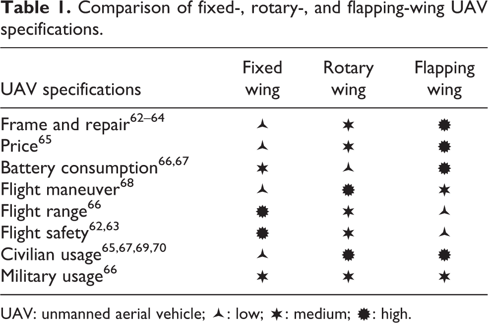
UAV: unmanned aerial vehicle;  : low;
  : medium;
  : high.
As a result of the research, it is seen that the most commonly used model in the rotary-wing UAV category is the quadrotor rotary-wing UAV. Four-rotor rotary-wing UAVs have gained great popularity among UAVs in recent years due to their small size, simple structure compared to traditional helicopters, high agility, fast maneuverability, vertical landing, and takeoff capabilities. Quadrotor systems are the perfect system for use in balanced flight tasks requiring robust controls. Due to its simplicity and low costs, there has been a significant increase in research and development in the last few years, particularly with regard to quadrotors, which are considered a possible solution in UAV applications. 71 –74
Quadrotor rotary-wing unmanned aerial vehicle
Four-rotor UAV, called quadrotor or quadcopter, is one of the rotary-wing UAVs that can takeoff and fly with four motors and two pairs of propellers (two clockwise and two anticlockwise) that are connected symmetrically to each other. With their high maneuverability, quadrotors are able to fulfill flight characteristics such as traveling in narrow areas, hovering, taking off, and cruise. 75,76 In addition to the ability to perform difficult and complex tasks in narrow and crowded environments, a quadrotor has more simple control mechanisms compared to other UAVs. 77 In addition to these capabilities, quadrotors can achieve high angular accelerations thanks to the arm length between their oppositely placed motors. This capability makes quadrotor more agile than most standard helicopters and aircraft. In recent years, quadrotors have gained an increasing interest in robotic and hobby applications due to their mechanical properties and their capabilities. 78 Figure 4 shows quadrotor UAV images in different models and shapes.

Technological advances in the fields of sensor, motor, battery, microcontroller, and wireless communication have made access to these types of equipment easier and cheaper compared to previous years. In this context, the use of these technologies in multirotor UAVs has resulted in a significant reduction in prices of UAVs. This has led to an increase in the number of users of UAVs. Advances in technology have significantly affected the use of UAVs. 79
Quadrotors carrying different equipment according to the purpose of working have frame structure, flight card, sensors (gyroscope, accelerometer, compass, barometer, ultrasonic vb.), propellers, brushless dc motors, electronic speed controller (ESC), battery, and remote control receiver, in general. 80 The working principle of the quadrotor is as follows. Control signals about the direction of the quadrotor are sent to the quadrotor with the remote control. Signals from the remote control are processed via the flight control card. Pulse width modulation (PWM) signals generated by the flight control card provide the values of the ESCs that are used to control the motors. Each ESC is connected to the motors and is used to control the motors. PWM signals are used to set the rotation values of the motors. The propellers connected to the motors are activated by the rotation of the motors and the quadrotor to takeoff. 81 In this way, the flight of the quadrotor is controlled. Figure 5 shows the types of equipment used on the quadrotors.

Quadrotor equipment. 80 (a) BLDC motor, (b) ESC, (c) propeller, (d) RF controller, (e) LiPo battery, (f) frame, and (g) pixhawk flight controller. ESC: electronic speed controller; Li-Po: lithium polymer; RF: radio frequency; BLDC: brushless direct current.
Quadrotors can perform basic flight movements on different axes by turning four motors at different speeds. Quadrotor has four basic movements, such as altitude, roll, yaw, and pitch. The altitude movement is used for the up and down movements of the quadrotor on the vertical axis. Roll movement is used to move left and right along the x-axis of the quadrotor. Pitch movement is used to move forward and backward on the y-axis of the quadrotor. Yaw movement is used to rotate around the z-axis of the quadrotor. 82,83 Figure 6 shows the quadrotor’s movements.

Quadrotor’s movements. 84
Figure 7 shows the axis movements made on the quadrotor depending on the motor movements. This figure shows the axis movement according to the speed values of the motors. For example, Figure 7(a) shows changes in the pitch angle due to the speed difference between the first and third motors; Figure 7(c) shows changes in the roll angle due to the speed difference between the second and fourth motors. 85 The figure shows forward, backward, right, left, turn left, turn right, takeoff, and landing movements, respectively.
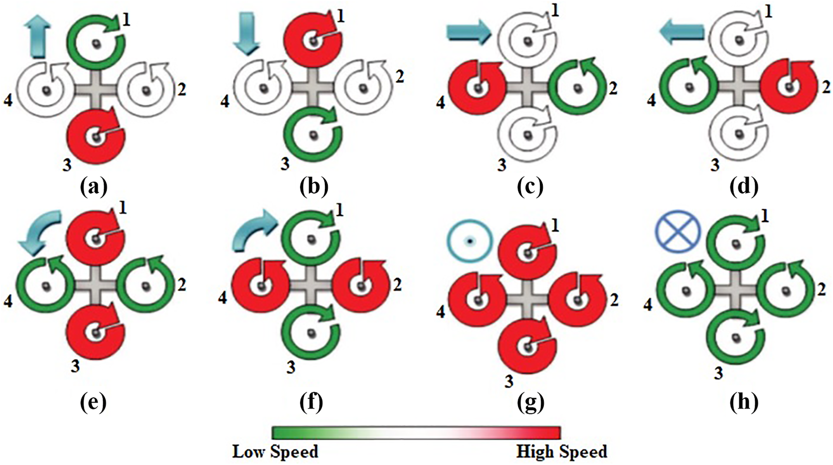
(a–h) Quadrotor axis movements. 85
Unmanned aerial vehicle battery types
Motorized and military-type UAVs generally use various fossil sources, such as gasoline, hydrogen, and methane. 86 Fossil fuels can produce more energy than batteries but have extremely low efficiency for internal combustion engines used in these UAVs. 87 The use of these fuels can also cause balance problems for mini UAVs. In UAVs with small size, the batteries instead of fossil fuels generally provide the power required for flight.
Currently, lithium polymer (Li-Po) batteries are used for small-sized UAVs due to their low weight. 88 Li-Po batteries are the most commonly used power source in mini UAVs because of their medium-specific energies, high specific powers, and high cycles; they are used in more than 90% of UAVs for academic and hobby purposes. 80,86,89 In Table 2, comparisons between four different batteries types (Ni-Cd: nickel cadmium; Ni-Mh: nickel metal hydride; Li-Po; and Li-S: lithium sulfur) used in UAVs indicate that lithium batteries are a better choice than others. 86,88,90 Li-Po batteries are the most widely used batteries on the market in terms of their specific energy and specific power. 90
Comparison of different type UAV battery. 88

UAV: unmanned aerial vehicle.
Energy sources used in UAVs include Li-Po batteries as well as renewable energy-based solar panels, 91 polymer electrolyte membrane fuel cells (PEMFC), 92 supercapacitors, 93 and laser technologies. 94 Li-Po batteries and supercapacitors are used to store energy, while solar panels are used to provide the energy required by UAVs. Studies with PEMFCs and laser beam are continuing experimentally.
Rotary-wing unmanned aerial vehicle charging stations
Batteries are used as electrical power sources in UAVs. Due to the high power consumption of the flight control system and the limits of the battery capacities used, the flight times of the UAVs can generally range from 10 min to 30 min. 31 –33,75 The potential use of UAVs is severely limited due to these limitations. UAVs cannot fully fulfill their intended use in certain applications due to the considerable limitation of flight range and operating time. To overcome such problems, innovations in battery technology and works on new power supplies continue. 75,95 To operate the UAVs continuously, the batteries must be charged or replaced during normal operation. Using autonomous stations that can charge the batteries on the UAV without the need for any human intervention, the flight time of the UAVs can be greatly increased.
There are effective battery charging applications using photovoltaic (PV) cells in fixed-wing UAVs. Thanks to the advantage of the wing length, the energy needed by the UAV can be obtained with the PV cells in the wings, and the long-term flight of the UAV can be achieved with this energy. For this reason, it has been observed that this is the most preferred method for fixed-wing UAVs. Since this method is not applicable for rotary-wing UAVs, charging stations have been developed. In charging stations, during the charging process of the batteries, it is possible to charge the batteries via physical cable connections or by transferring power wirelessly. Wired transmission is more efficient than wireless but requires more maintenance. In addition to charging, the stations that allow the battery to be replaced are also used to continue for the flight of the UAV. 75,95 In addition to the charging process of batteries, battery replacement station is used for rotary-wing UAVs. Within the scope of this study, a compilation study was performed on the stations developed for charging the batteries of the UAVs. In this article, wired, wireless, and battery replacement charging stations were discussed.
Unmanned aerial vehicle wired charging stations
Wired charging is the process of transferring energy between the UAV and the power source by means of a cable or connector connection. The energy needs of the charging platforms are met through the power lines (copper contacts, connectors, etc.) wrapped in the charging platforms in fixed or mobile charging stations. Charging process is carried out by contacting the charging apparatus wrapped in various parts on the UAVs with the charging platforms at the station. Since power lines are connected to fixed positions in the charging platforms, short-circuit problems may occur due to misalignments during landing. To eliminate these problems, charging station has been carried out in different ways.
Mulgaonkar 95 has realized a charging station for autonomous charging of micro-unmanned aerial vehicles (MAVs). The station has been specifically designed for UAVs to perform surveillance flights. The charging stations are located at a fixed point and allow multiple UAVs to be charged at the same time. The charging station is designed to allow the UAVs to land autonomously, charge the battery on the UAV, and resume their duty. The energy is supplied to the station with the power cables at the bottom of the metal plates in the station. The UAVs coming to the charging station are connected to the metal plates in the station by means of metal connectors located at the bottom. The batteries are charged with the energy transmitted through the connectors. Three MAVs were used in the system. While any MAV is charging, other MAVs continue the task. The station performed is shown in Figure 8(a). As shown in this figure, the part with the red arm of the UAV must land to the plate covered with a red stripe. There is a risk of short circuit if an incorrect landing occurs.

In the literature, 96,103 Cocchioni et al. have realized a study on the charging process of UAVs by collaborating between different devices. By interacting with unmanned ground vehicle (UGV) and UAV, they built a mobile charging station platform that will allow the UAV to charge. A ground control station software was developed to provide coordination and synchronization between UGV and UAV. During the charging process, fast charging is used instead of a balanced charging. The designed platform is developed as a passive charging mechanism that allows the battery to be charged within 20 min but no full charge. The charger is directly connected to +12 V DC power. The proposed station is shown in Figure 8(b). As shown in this figure, charging realizes in the event that the copper plates in the dome-shaped lower region and the connectors on the feet of the UAV come into contact. The fuse is installed to prevent any short-circuit problems in the system. In this study, battery charging is selected instead of battery replacement because of development time, cost, and platform complexity.
Song et al. 97 developed a mixed-integer linear programming model to support the processes in the system to regulate flight operations of a large number of UAVs to be used in flight missions and logistics facilities. In addition to the intended system, the battery charging station is realized. There are four copper pads in the system (one for each leg of the UAV). Four copper wires (three for terminal lines and one for ground) from inside the Li-Po battery on the UAV have connected to four legs of the UAV for charging the battery. In case the copper cables on the legs of the UAV come into contact with the copper pads on the station, charging is started. During the charging process, charging cannot be not performed while AR Drone 2.0 is running. There is a large circular button in the center of the station. When the UAV lands at the station, it activates the system by touching this button and a circuit controlling the UAV becomes active. After 5-s of landing, the UAV’s power is switched off and charging is started. After the charging process is completed, the signal is given with a light-emitting diode (LED) by the charger. The station senses this situation, finishes charging, and activates the battery. The station performed is shown in Figure 8(c).
Leahy et al. 98 realized a station that would allow the automatic charging of multiple UAVs, which would serve as permanent surveillance. Automata-based techniques have been used to enable UAVs to move without collision. The charging station allows the UAVs to be used in real-flight missions. The two UAVs used in experimental studies to confirm the theoretical results have landed approximately 50 times in the charging station located at two different points. The station is shown in Figure 8(d). The Hyperion EOS0720i Net3AD charger provides power to the station. In case of contact with the steel connectors mounted to the feet of the UAV and the stainless steel pads in the station, the battery charging process is started. The processes on the platform are monitored in real time.
Valenti 99 and Dale 104 have conducted the design, modeling, testing, and realization studies of a fully autonomous charging station for UAVs operating with small-sized batteries. The designed charging station was used to perform long-term flights and to manage tasks on multiple UAV flights. The charging station is shown in Figure 8(e). An inverted pyramid-shaped wall design has been designed to prevent the UAV that will land at the charging station to go to the wrong position. This method has been chosen among the active position error correction methods because of its simplicity, ease of use, and effective use in tolerating landing error methods. With this design, the UAV is landed on the copper pads on the charging runway. In case the copper connectors on the legs of the UAV come into contact with the four copper plates on the station, charging is started. While the “+” power line is given from two copper plates, “−” power line is given from two other copper plates. A number of charging stations for multi-UAV task management have been established. The charging stations have been used to experiment with multiple quadrotors cooperating with each other.
Kemper et al. 100 conducted a study to evaluate, analyze, and design the economical consumption of battery charging stations used for helicopter-type UAVs. Within the scope of the studies, the features of the charging station, such as modularity, cost, complexity, terminal connections, and matching, have been considered and axiomatic designs have been made. Axiomatic designs of both refueling and exchanging stations for helicopter-type UAVs have been made, and consequently, it has been advocated that it is appropriate to use refueling stations for UAVs with low coverage and exchanging stations for UAVs with high coverage. The proposed station was realized, as shown in Figure 8(f).
The charging station, 101 which was developed as a result of the studies at Boston University, can charge battery on four-rotor rotary-wing UAVs. In case of contact with the conductive tape wrapped on the legs of the rotary-wing and the copper bands on the station, charging is started. The controlled charging of the battery is made by switching with the relay system between the flight control card, ESCs, and the battery charger. The designed station was realized using a 3D printer. This station is shown in Figure 8(g).
The charging station, 102 which was developed as a result of the studies at Nevada University, can charge the battery on six-rotor rotary-wing UAVs. In case of the copper bands wrapped around two legs of the rotary-wing and the copper contact points on the charging station come into contact with each other, charging is started. Thanks to the inclined arms, misalignment errors are prevented during landing. A more stable structure is formed since the foot supports are connected to each part of the hexagonal pulley. Three different tests were performed to test the validity of the station. In the first test, the UAV was manually placed on the platform and the connection between the station and the UAV was tested. After landing, the status lights on the station became active and the green light was on. In the second test, the UAV was manually landed and charging was performed while the UAV was at work. In the last test, it was checked how fast the battery will be charged and it has seen that the battery was charged in 69 min and 56 s. The realized station is shown in Figure 8(h).
The charging platforms produced by SkySense, 105 HiveUAV, 106 and HeishaTech 107 are among the works used in the charging of UAVs. Although their general hardware structures, features, and areas of use are different, their common purpose is to provide platforms for charging the UAV on mission flight and increasing the flight time of UAV.
The comparative analyses of the wired charging stations developed for the rotary-wing UAVs are given in Tables 3 and 4. Table 3 presents the features of the characteristics of the charging stations proposed for UAVs and Table 4 presents the features of the UAV specifications used in the wired charging station studies.
Comparison of wired charging station specifications.

UAV: unmanned aerial vehicle.
Comparison of UAV specifications used in wired charging stations.

UAV: unmanned aerial vehicle.
Unmanned aerial vehicle wireless charging stations
Wireless power transfer (WPT) is the process of transferring electromagnetic energy between the transmitter and receiver sources without using any connection physical cables. This technology is based on the idea of the transfer of energy by air, without any using intermediate, that was put forward by Nicola Tesla from the beginning of the 20th century. 108 In a typical WPT system, the transmitter source converts the electrical energy into a time-varying electromagnetic field. After the converted energy is transferred to the receiver, the electromagnetic field is converted back into electrical energy and the energy transfer is completed. 109 In WPT applications, energy is transferred between two coils without physical connection.
Junaid et al. 110 have developed a charging station that supports wireless charging for UAVs that can work indoors. The power transfer at the station is carried out wirelessly via the transmitter and receiver coils. With the station, the UAV, which has autonomous navigation, is charged without human intervention, and a cheap solution is provided that will allow the flight time of the UAV to be increased. The charge level of the battery is controlled by the low battery detection system on the UAV. When the battery charge level drops, the UAV lands at the charging station and starts charging. After the charging process is completed, the UAV continues its flight mission. The proposed system shows a 50% increase in power transfer efficiency compared to existing systems used in the WPT process. In the designed system, a MATLAB interface is made to communicate between the open-source flight controller and the ground station, and sensitive vision sensors (VICON) are used for controlled landing operations. The station performed is shown in Figure 9(a).

Junaid et al. 111 realized a cost-effective charging station for UAVs in the outdoor flight missions to be able to land autonomously and to be charged wirelessly without the need for any human intervention. UAV battery can be charged without any cable connection. Within the scope of the study, Global Position System (GPS) sensor, image-based closed-loop target detection, and tracking system were used for controlled landing operations of UAVs in the outdoor environment. The built-in camera is used to detect the shape, color, and position of the target defined in the image frame in the charging station. To detect the red circular target on the station, the images captured from the camera on the UAV are passed through image processing processes. In the study, a commercial drone named AR Drone was used and three receiver coils were installed as serial under the UAV. Three wireless charging modules of the XKT-510 model, placed under the red circle on the station, are connected to the power supply in the station. The battery is charged with energy communication between the receiver and transmitter modules. It has been observed that the study performed in the test and analysis processes achieved an average of 75% success in the WPT process. The station performed is shown in Figure 9(b).
Choi et al. 112 realized an autonomous charging station based on magnetic induction principle and distance sensing for UAVs. In the designed system, there are two sliders moving on the X and Y axes, two motors on these slides, one ultrasonic sensor, and two laser distance sensors. Arduino Uno controller board is used to manage the control processes at the station. In the developed system, after the UAV landing on the platform, the position of the UAV is detected with laser sensors in the station and the induction coils are brought to the lower part of the UAV by moving the sliding system. WPT is made from the station to the UAV through the transmitter coil on the station platform and the receiver coil on the UAV. After the charging process is completed, the UAV takes off and continues its duty. The charging station can carry out charging without any precise landing or positioning. During the wireless charging process, a battery with 700 mA and 3.7 V capacity is charged in about 75 min, while it is charged in 50 min with wired charging. In this regard, efforts to increase the efficiency of energy transfer at the station continue. It takes 5 s for the positioning system to detect the receiver coil and make the correct alignment. The station performed is shown in Figure 9(c).
Jung et al. 113,114 realized a WPT station for UAVs that is more useful against misalignments during landing and safer than direct metallic contact. In the designed system, inductive wireless power transmission is performed using receiver and transmitter magnetic rings. A magnetic field was created using inductor coils on both the transmitting and receiving sides. Small induction coils are used around the UAV to increase efficiency, faster recharging, and reduce sensor interference within the system. To conduct inductive wireless power transmission, an unmanned ground station (UGS) has realized containing four pairs of inductive receivers and transmitters. In the UGS, two PIR motion sensors and four pressure sensors were used to detect the landing of the quadrotor-type UAV. To increase the charging efficiency, four positioning rods have been used to ensure the correct alignment of the receiver and transmitter magnetic rings and to place the misaligned UAV in the center. If the UAV is not at the proper distance during the charging process, charging is not performed. The station performed is shown in Figure 9(d).
Ke et al. 115 presented a wireless air charging system, where the electric unmanned aerial vehicle (e-UAV) can be charged wirelessly and without the need for human access. In the proposed system, the magnetic field is created in order for the e-UAV to receive enough energy from different points on the charging pad and it can transmit sufficient power at a high efficiency with the proposed system. Simulation and experimental studies have been carried out to prove the validity of the system. Within the scope of simulations, studies have been carried out on two key factors: distance and relative position between the receiver and transmitter coil. In simulations, electromagnetic field distribution of the wireless power transmission system was realized using the JMAG Designer and the finite-element method. With the developed prototype, the system has been tested at different frequencies. An experiment was conducted on the operation of the UAV and the test pad in different relative positions. It has been seen that the receiver coil reached its maximum power (6.6 W) at a frequency of 370 kHz. In the system, the maximum output power is calculated as 6.9 and the minimum output power as 6.3. The 8% power loss shows that the system has high tolerant capability against misalignments. This rate increases to 20% due to the misalignment of the e-UAV. The station performed is shown in Figure 9(e).
Rohan et al. 118 developed an advanced battery charging system that allows UAVs to be charged using the wireless power transmission technique operating on a resonant inductive connection basis. For using charging processes, there are multiple power transmitters on charging station and one receiver on UAV. In the system, a new method based on the hill-climbing algorithm is proposed to control the connection between the receiver and transmitter systems without the need for any physical sensors. A practical test bench has been developed for the proposed system. A four-way directional XY table has been used for the developed charging station because of controlling the position of the transmitter coil. On the XY table, four transmitter coils are used for energy transfer and two stepper motors are used for positioning. When the UAV lands on the charging station and the XY table starts moving the transmitter coil to the correct position using the hill-climbing algorithm, the transmitter coil and the receiving coil begin to inductively match. Wireless power transmission starts at maximum efficiency within 2 s after the UAV lands at the charging station. The system has been designed fully automatically and different landing scenarios have been tested to reduce the poor landing effect. Regardless of the position of the receiver coil, the centers of the transmitter and receiver coils in the charging station are precisely aligned with 98.8% accuracy. Approximately 85% efficiency was achieved in wireless power transmission.
Yang et al. 116 designed the asymmetrically coupled wireless power transmission (WPT) system to charge UAVs wirelessly. The system has optimized coupling structures and parameter values to increase horizontal tolerance and performance. Modeling and analysis of wireless charging process have been done. By modeling and analyzing the WPT system, the parameters to be used to determine the efficiency of the received power and wireless transfer are obtained. The quality factor and horizontal tolerance are optimized by simulations and comparisons on the structure and parameter values of the coupled coils. When looking at the energy transfer processes in the designed system, solar energy taken from PV panels is converted to AC energy with inverters. AC energy is stored in supercapacitors and batteries. The stored energy is transferred to the high-frequency AC via the high-frequency inverter during charging and then transmitted through the transmitter coil after it is balanced on the primary side via the high-frequency AC. Receiver coils on UAV received energy wirelessly with its resonant magnetic connection. The received energy is converted to DC energy after compensation, rectification, and filtering processes, and the battery is charged. An experimental platform has been prepared to test the accuracy of the analysis and design results. As a result of the tests, it has been observed that the wireless power transmission efficiency is 57.94% and the power received is always higher than 64 W. The misalignment of the coupled coils is tolerated. The station performed is shown in Figure 9(f).
Chen et al. 117 presented a project that will provide automatic and high-efficiency wireless energy transfer for a 3D printed UAV. The proposed system consists of the receiving coils to be used to charge the 3S Li-Po battery and the transmitter coils in the pad. Wireless power transmission side is powered by 24 V DC voltage and operates at a frequency of 180 kHz. On the receiver side, three XKT-801 WPT modules are used: one for each cell of the Li-Po battery. A specific part has been added on the UAV for the receiver system. Three receiver coils are wound on this part. When UAV, that is, manually operated UAV approaches the transmitter coil, the LED on the battery charging module lights up red and indicates that the battery charging process is started. When the UAV leaves the working distance of the transmitter coil, the LED lights blue and indicates that the battery charging process is cutoff. As a result of the tests, it has been observed that a distance of up to 12 cm must be found between the UAV and the transmitter coils in order for the system to operate efficiently. When the transmitter and receiver coils enter the effective range, wireless charging starts again. The performed charging system is shown in Figure 9(g).
Campi et al. 119 established a WPT base station based on magnetic resonance connection for UAVs and performed simulations related to the system. In the study, the receiving coil is on the UAV and the transmitter coil is on the base station. Simulation studies were carried out on the positioning of the round-shaped coils at the bottom of the designed UAV. In the first simulation, the volt, current, and efficiency values obtained in three different positioning situations (0, 100, and 200mm) are calculated. In the second simulation, a large misalignment (200 mm) between UAV and base station is performed. During the simulations, the operating frequency of the system is fixed to 150 kHz. Campi et al. 120 developed a mobile charging platform that can move on x and y axes to eliminate the problems that may arise due to the wrong positioning of UAVs during charging processes and to realize a high-efficiency WPT. In the developed system, the transmitting coils are located in the base station and the receiving coils are on the UAV. After the UAV lands on base station, the transmitter coils are automatically moved to try to find the optimum position of the receiving coils. The method used in the exact position of the receiver coil is performed by monitoring the input impedance of the wireless power transmission system. Input impedance is measured by scanning the landing area with the motorized positioning system for the transmitter coil in the base station. As a result of the measurements, the charging process is started after the location of the receiving coils is determined.
Wang and Ma 121 designed an automatic charging station for UAVs that include modules such as power supply, charging, and control module to determine the UAV’s departure and return time, GPS, and wireless network device. In the study, an UAV is designed that can fly autonomously, self-charging, and transfer navigation data through an autonomous cruise network system consisting of a large number of smart charging sticks and GPS devices. When an energy alarm is given by UAV, the closest charging station point is determined with the autonomous cruise network system, and then, the position is roughly determined by GPS device. When the UAV gets closer to the charging point, position determination is done visually for landing to the correct position, and then, landing is performed. WPT is performed with magnetic resonances. Since electricity grid and solar energy are used in the designed charging station, it is possible to install it wherever it is needed.
Song et al. 122 proposed a charge coil that can eliminate the reduction in charge efficiency due to central misalignments in UAV-enabled WPT systems. In theoretical analysis, basically, the structure, size, and weight of the charging coil and the limitation of the operating characteristics of the UAV are made. The parameter values of the charging coil are optimized to tolerate misalignments that may occur. Finite-element analysis method is used to optimize the charge coil. In the simulation studies carried out in the MATLAB environment to verify the performance of the charge coil, the system input voltage is selected at a maximum of 250 V, and lithium battery pack is selected as load. As a result of the simulation and experimental studies, it was observed that the efficiency of the transmitted power was about 91% when the offset distance was below 200 mm. The working frequency of the WPT system was chosen as 50 kHz as a result of the studies. In the WPT system, the input power level is at a maximum of 215 W, the output power level is at a maximum of 195 W, and the charge current is at a maximum of 12 A.
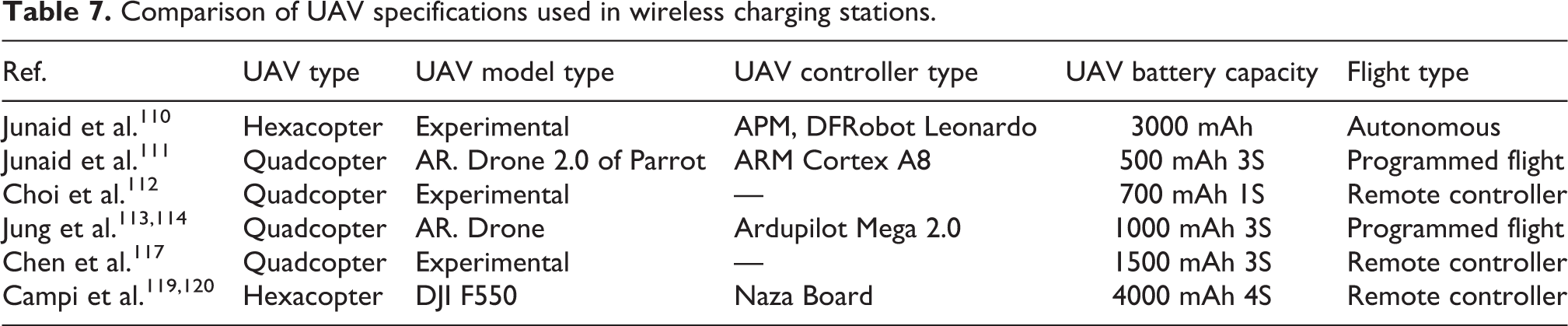
The comparative analyses of the wireless charging stations developed for the rotary-wing UAVs are given in Tables 5 to 8, respectively. Table 5 presents the characteristics specifications of the wireless charging stations for UAVs, Table 6 presents the WPT specifications in the wireless charging station, Table 7 presents the UAV specifications used in the wireless charging station studies, and Table 8 presents the transmitter and receiver coil specifications used in wireless charging.
Comparison of wireless charging station specifications.

UAV: unmanned aerial vehicle.
Comparison of WPT specifications in wireless charging stations.

Comparison of UAV specifications used in wireless charging stations.
Comparison of coil specifications used in wireless charging.

Unmanned aerial vehicle battery replacement stations
Charging stations, called battery replacement/swap, are stations for autonomous replacement of the battery on the UAV. Thanks to the mechanical systems in the station, it is detected that the UAV has landed and the position of the battery is determined. After this process, the battery in the station and the battery on the UAV are replaced and the flight mission continues. The process of changing the battery while the UAV is running is called hot swap, and the process of changing the battery while it is stationary is called cold swap. In this type of charging stations, landing operations and mechanical system applications should be done smoothly. Otherwise, problems may occur during battery replacement procedures.
Toksoz et al. 123,124 designed and implemented a battery replacement system to significantly increase the operational flight times of small-sized UAVs. Simultaneous battery replacement and charging of batteries were carried out to overcome the time problems experienced in current charging approaches. Thanks to the autonomous system, the battery on the UAV in the mission flight, which is full, is quickly replaced and the batteries that run out at the same time are charged at the station. During the test studies, a mission flight of approximately 3 h was carried out with three UAVs. More than 100 battery replacements have been carried out with batteries, each of which has a flight capacity of 8–10 min. The realized charging station enables uninterrupted flight missions by being applied to multiple UAV systems. The performed charging system is shown in Figure 10(a).

Lee et al. 125 built a charging station that allows the UAV battery to be replaced with a new battery autonomously and to charge more than one (four pieces) battery at the same time. Precise landing control algorithms are used to achieve a precise landing during landing operations. With the newly designed system, it is aimed to improve the previous designs. During the battery replacement process, there is no power loss and no data loss thanks to the “hot battery swapping” process. With this application, which stands out as the biggest innovation brought by the system, information during the flight is constantly protected. The performed charging system is shown in Figure 10(b).
Dong et al. 126 developed a charging station for autonomous replacement of the battery of UAVs. The mechanical system of the power relay platform for the multirotor UAV was designed and manufactured. A control system has been implemented to combine independent mechanical systems and to control the mechanical structure. Considering the experiments, it has been determined that the success rate of the automatic battery replacement system is approximately 80%. The performed charging system is shown in Figure 10(c).
Fujii et al. 127 developed an automatic battery changing mechanism called “endless flyer” for UAVs that will allow continuous flight without the need to change batteries manually. In the studies carried out, firstly, the landing performance of the UAV in a noiseless environment was evaluated, and according to these evaluations, the design of the platform and the landing errors were determined. Secondly, the battery replacement process was carried out after the UAV’s landing. Landing on the platform, the UAV is moved toward the center area on the platform. Then, UAV was brought to the points where the landing pads are located. After the indoor tests, the charging station was tested in the outdoor environment. As a result of the tests performed, success was achieved in landing process by 90% (18/20) and in exchanging process by 100% (9/9). The performed charging system is shown in Figure 10(d).
Swieringa et al. 128 developed an autonomous battery replacement system for a large number of small-sized UAVs. The implemented system includes a battery change mechanism and online algorithms for the management of resource addresses, monitoring the vehicle status, and for precise landing on the landing runway above the battery replacement mechanism. In the station, after the helicopter UAV lands on the runway, the platform under the runway moves and brings the battery unit under the UAV. After reaching the relevant position, the battery at the bottom of the helicopter is removed and replaced with the full battery. A simple PD controller is used as the control algorithm during the landing processes. All transactions performed are recorded on the server named “autonomous control environment.” The performed charging system is shown in Figure 10(e).
Suzuki et al. 129 made a comparison of different automatic battery exchange systems for helicopter-type UAVs and realized a battery replacement station for helicopter-type unmanned aerial systems. Within the scope of the studies, models of battery replacement and battery charging processes were created with Petri net graphic tool. Petri net graph tool is a graphical tool used to define distributed concurrent, parallel, asynchronous, deterministic, and stochastic stepping processes. With Petri net graphic tool, models of battery replacement and battery charging processes are compared in terms of cost and time. In addition to these comparisons, a prototype sample battery replacement system was proposed and information about the hardware was given. The proposed charging station is designed for use in UAVs of different structures.
The comparative analyses of the battery replacement charging stations developed for the rotary-wing UAVs are given in Table 9.
Comparison of battery replacement station specifications.
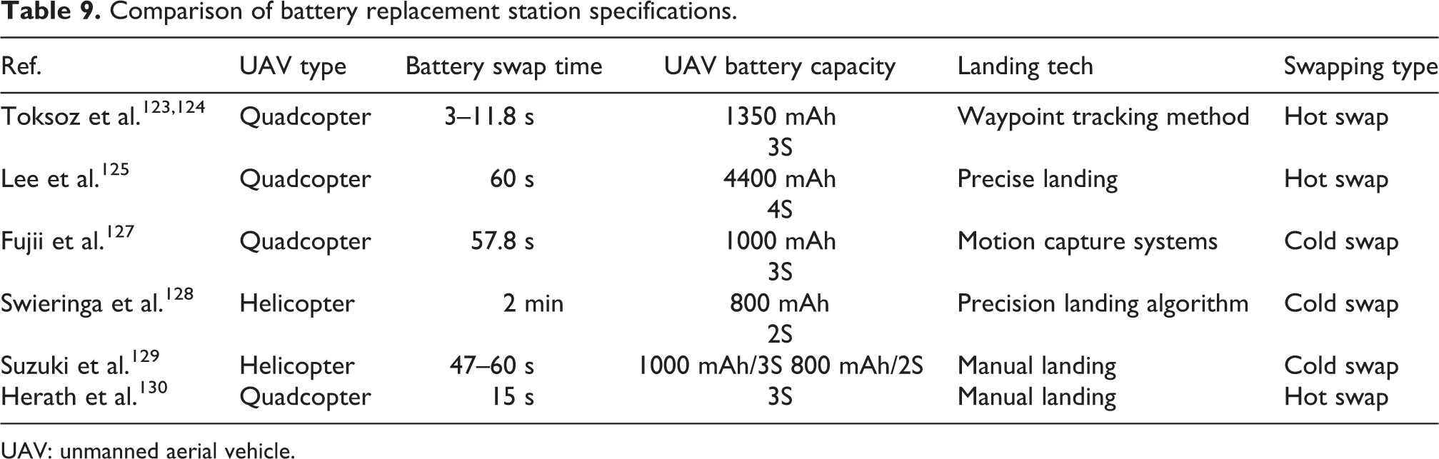
UAV: unmanned aerial vehicle.
Photovoltaic cell-based charging
The use of PV cells is one of the methods used to increase the flight times of UAVs and charge batteries. It is ensured that the battery on the UAV is charged with the help of sunlight through the PV cells. Both batteries and PV cells are used in UAVs used in this way. When the sunlight is available, the power needed by the UAV is provided by the PV cells, otherwise, the energy requirement is provided from the battery. Studies on solar-powered UAVs show that important parameters such as the positioning of the PV cells, the angle of incidence of the sun, and the temperature intensity affect the charging process. 131,132 For this reason, this method may be inadequate during periods of insufficient sunlight.
Although it is possible for UAVs working with PV cells to fly for long periods, different options can be used when there is no sunlight. The first approach is to have an additional power supply. 133 Another approach is to increase the battery power on the UAV and the size of the PV cells by calculating the periods when there is no sun. This approach limits the capabilities of UAVs in situations that require precision flight. 134 Since the PV cell structure requires a certain amount of wing length and carrying capacity on the UAV to be applied, it can only be applied to fixed-wing UAVs and cannot be used practically for typical multirotor UAVs. 108
Charging with laser beaming
Laser beaming method, which is used as an external energy source, is one of the methods that enable UAVs to be charged and is generally used in military missions. 135 A laser beam of a specific frequency and wavelength feeds PV cells on the UAV. With these PV cells, the UAV is powered and the battery is charged. 136 Maximum power point tracking methods are used to benefit from the energy obtained from PV cells at the maximum level.
Laser beaming method can be used for fixed-wing and rotary-wing UAVs, regardless of environmental conditions. The biggest disadvantage of this method is that the laser energy source is close to the UAV, and therefore, the energy source must be moved as mobile. This situation limits the use of UAVs in long-range flights. The use of this method in some areas has been restricted due to the potential dangers of laser beams for human health and serious disturbances in living environments. 108,137
Conclusion
UAVs have become the focus of attention of many users with their ability to fly at different speeds, versatile movement, hovering, fast maneuvering, and flying indoor and outdoor and their popularities have increased day by day. Despite so much interest in UAVs, there are some disadvantages such as limited carrying capacity and low flight times. Li-Po and Li-ion type batteries are generally used in UAVs as they have rechargeable features. Although improvements to battery technology continue, performed flights using existing batteries generally last between 10 min and 30 min. 31 –33 Low flight times reduce the flight range of the UAVs and cause them to fail to perform the given tasks. This situation prevents the UAVs from operating at full capacity. To meet all potentials of UAVs and to overcome the problem of low flight time, charging stations are being developed. With the developed charging stations, it is possible to autonomously charge UAVs on-duty flight without human intervention.
To develop an autonomous system, battery charging should be done automatically. With the charging pads developed for this purpose, UAVs can be charged autonomously with wired or wireless connections. In wired connections, energy is used efficiently, but due to the mechanical contacts in the system affected by environmental conditions, the reliability of the system decreases. In wireless connections, the system is superior in terms of reliability but the efficiency is less. In wireless communication, decrease in energy efficiency can be seen due to the alignment problems of the receiver and transmitter circuit elements. 120
This study has focused on the charging stations realized for rotary-wing UAVs. Within the scope of this article, charging station works, which can charge the batteries of rotary-wing UAVs as wired (direct contact), wireless (wireless induction), and battery replacement (swapping), are reviewed. In this context, three subcategories were formed and charging stations found in the literature searches were evaluated in related categories. During the evaluations, brief summaries of each study were given and comparative tables of the general characteristics of the studies were prepared.
Although the charging stations for UAVs are different in terms of hardware, technological, mechanical, and usage areas, they have a common purpose. It is to increase the flight times of UAVs by charging or changing batteries autonomously without human touch. In this context, the same process is carried out using different charging station.
Footnotes
Declaration of conflicting interests
The author(s) declared no potential conflicts of interest with respect to the research, authorship, and/or publication of this article.
Funding
The author(s) received no financial support for the research, authorship, and/or publication of this article.