
Abstract
The underwater vehicle-manipulator systems (UVMS) face significant challenges in trajectory tracking and motion planning because of external disturbance (current and payload) and kinematic redundancy. Former algorithms can finish the tracking of end-effector (EE) and free of singularity redundancy solution alone. However, only a few analytical studies have been conducted on coordinated motion planning of UVMS considering the dynamics controller. This article introduces a combined dynamics and kinematics networked fuzzy task priority motion planning method to solve the above problems. It avoids the assumption of perfect dynamic control. Firstly, to eliminate the kinematics error, a dynamic transformation method from joint space to task space is proposed. Without chattering, an outer loop sliding mode controller is designed for tracking EE’s trajectory. Further, to ensure the underwater vehicle’ posture stability and joint constraint, a task priority frame with kinematics error is used to planning the coordinated motion of UVMS, in which the posture and joint limits map into the null space of prioritized tasks, and weight gains are adopted to guarantee orthogonality of secondary tasks. On top of that, the gain weighted are updated by the networked fuzzy logic. The proposed algorithm achieves better coordinated motion planning and tracking performance. Effectiveness is validated by numerical simulation.
Keywords
Introduction
The vehicle-manipulator system has a more complex external environment and force characteristics in the space and ocean. It realizes more effective motion control and grasping accurately, which highlighted its research significance. 1 –3 The underwater vehicle-manipulator systems (UVMS), remote operating vehicle (ROV), or autonomous underwater vehicle (AUV) with manipulators is a vital tool for underwater tasks such as marine science, marine engineering, and military applications. 4,5 However, given the kinematics redundancy, processing the constraints of each joint (inequality condition) and the motion stability of AUV is still not available in the unified form. 6,7 When facing parameter uncertainty and external disturbance, the controller still has some problems, mainly reflected in poor convergence, insufficient stability and chattering. 8 –10 In summary, the practical solutions to the abovementioned issues are rarely examined in the research.
Although the redundancy of the UVMS increases manipulability, it causes the kinematics solution to be nonunique and leads to the necessity of redundant decomposition in trajectory planning. This redundancy seriously affects online trajectory planning and motion coordination. 6 Offline trajectory planning tasks cannot be effective in a harsh environment. There are two solutions to the UVMS redundancy: one approach is the augmented Jacobin, which may bring the algorithm singularity, and the other is based on pseudoinverse approaches to assume the end-effector (EE) path, which brings space inconsistencies.
Once the trajectory of the EE is given, the motion of AUV and each joint needs to be considered. Antonelli 2 proposed a fuzzy redundancy coordinated motion control method and adopted the inequality condition to activate secondary tasks. Based on the pseudoinverse approach, Santos 11 used a fuzzy expert system to avoid singularity posture on the UVMS. Both overcome the kinematics singularity effectively. However, they still fail to solve optimal redundancy.
To the best of the authors’ knowledge, researchers have proposed a variety of trajectory planning methods for UVMS at different criteria, such as obstacle avoidance, 12 free of singularity, 13 shortest time, 2,14 optimal torque, and lowest energy consumption. 15 Kim et al. 13 solved kinematics singularity by dynamic distributing tasks based on task priority (TP) method. Under this idea, it is easy to obtain the TP refactoring criteria and evaluate its performance. For minimizing systems and restoring torque, Jonghui et al. 15 designed an optimal controller with a nonlinear disturbance observer to resist parameter perturbation, external disturbance, and actuator nonlinearity. Sadly, the coordinated motion is not concerned. In the literature, 16 the resistance optimization function was added in inverse kinematic (IK) solution, and a coordinated motion planning algorithm was used to minimize energy consumption. After the closed-loop IK combined with redundancy has given a stability analysis, Antonelli 17 proposed priority IK control algorithm mapping tasks as the unified formula of the first-order form.
As an intelligent algorithm, the fuzzy logic can compensate the model and find the control parameters. Proportional integral derivative (PID) tuning parameters are found by fuzzy logic to have a higher motion precision. 11,18 Fuzzy logic 6,19,20 and neural networks 9 are usually used to solve the task weights in real time. Fuzzy logic, as a higher-level supervisor, can possess applicability instead of constant.
Solving the lumped uncertainty for the controller of UVMS has attracted many scholars to study. 21 –26 In a complex environment, the variety of disturbances include (a) ocean current, (b) payload changes, (c) lift or resistance, (d) noise (noise caused by the sensor and actuator error), (e) time delay or joint lag, and (f) friction and other disturbances. Simultaneously, uncertainty generally includes model parameter uncertain item (mainly generated by model inaccuracy) and parameter uncertain item (often not directly reflected as model parameters).
It generally divides into two categories to solve this problem. The first solution is to consider the disturbance and uncertainty as to the lumped uncertainty; the second solution is to deal with them separately by subdividing each characteristics. In the first solution, Ahmadi and Fateh 27 approximated the lumped uncertainty through the Taylor series, and Han et al. 10 designed an inertial delay controller to estimate it and improved the control effect using a fuzzy compensator. Although this method resulted in a relatively simplified controller, a bottleneck was encountered to control accuracy. The second solution, more targeted, is often based on the characteristics of disturbance and uncertainty. Considering (b) and (d), Mohan and Kim 8 adopted the extended Kalman filter (EKF) algorithm to construct disturbance compensation; Salloom et al. 9 analyzed (c) as an unknown external disturbance and considered the nonparametric uncertainties as (f); the literature 5,9 –13 designed EKF, adaptive algorithm, and observer compensation, respectively, for (d). Before using the time delay estimator, Yang et al. 22 summarized (e) as (d). The abovementioned classification of disturbance terms is the basis to provide a compelling for the optimization of the controller. Similarly, the parameter uncertainty term in the uncertainty is passed through Legendre polynomial, 22 EKF, 8,10 respectively, achieved online estimation. Sadly, the kinematics redundancy of UVMS is less reflected in the controller designed with lumped uncertainty.
Under the highly coupling of UVMS dynamics, Kim et al. 8,28 proposed a sliding mode control (SMC) with UVMS motion redundancy considered to ensure task completion successfully when the target object’s shape, inertia, and others are unknown. Combined kinematics and dynamics control method for UVMS was proposed for underwater swimming manipulator by Borlaug et al. 29 It allows us to design the kinematic and dynamic subsystems together without the assumption of perfect dynamic control. In this article, the SMC in position needs to be further strengthened. A condition is set that model can be decoupled in dynamics and kinematics separately. 7,13 The singularly robust multitask priority framework (SRMTP) eliminates this condition. 17 It brings us an idea. However, in the process of combined kinematics and model uncertainty error, the quality of control still needs to be improved.
Inspired by the above studies, a novel motion planning and coordinated controller for UVMS is proposed in this article. This contribution to this article is that the proposed method within the multitasks can achieve precise and robust performance under the disturbances. First, an outer-loop sliding mode controller is proposed, where the dynamics transform from joint space to task space for avoiding joint error accumulation, and the outer loop eliminates the kinematics error in the task space. Second, the multiple TP motion planning and coordinated frame of UVMS is constructed, where weighted gains are adopted in the null space of prioritized tasks to guarantee orthogonality of secondary tasks, and the task error is feedback to the controller. Third, to determine secondary tasks’ contribution, a networked fuzzy logic is employed, instead of traditional fuzzy redundant rules. Last, the effectiveness and feasibility of the proposed method are verified by numerical simulations.
In this article, the model of UVMS kinematics and dynamics is derived in the second section, and the third section is concerned with a tracking controller combined with kinematics error. In the fourth section, the proposed coordinated motion planning method is constructed. The fifth section verifies the effectiveness of the proposed method by simulation experiments. Conclusions are presented in the sixth section.
Problem setting
UVMS consists of the AUV and the manipulator. Figure 1 shows the UVMS in each coordinate frame, the AUV is connected to the EE through link Li and joint qi (it could be either prismatic or revolute). The following coordinate systems have been established:

Sketch of underwater vehicle-manipulator systems.
The velocity kinematics equation of the UVMS is

where
Consider the dynamics of UVMS in joint space as follows

where
Under the corresponding accurate model,
Further, equation (2) with unknown matrix terms can be expressed as

Consider the unknown matrix terms abovementioned as an external disturbance. This idea can be compensated and estimated in real time using the controller designed in the next section.
So, rewrite equation (3) as follows

where
In the UVMS model, the AUV is underactuated in the AUV body frame, and its design parameters are given in Table 1. The manipulator,
Design indicators for AUV.

AUV: autonomous underwater vehicle.
Joints parameters in manipulator subsystem.

Design of a tracking controller
It is worth noticing that the problem of uncertainty and external disturbance, as the precondition of UVMS coordinated motion planning, is based on a sliding mode controller. 22
Given the EE desired velocity
Dynamics from joint space to task space
Firstly, EE error is defined in the task space

Further, get the time derivation of e

In equation (6),
Introduce

where ke is the error gain, expressed as constant.
Differentiate it

Combined with equations (1), (3), and (8), the dynamics in task space is as follows

where
Rewrite as equation (10)

where
Assuming that
From the abovementioned, the tracking error of EE in the task space consists of two. The first is the accumulation, in the task space, of trajectory tracking errors from joint space, and the other comes from the kinematics of the desired pose in the joint space, as shown in equation (1). This error in the task space from the desired pose of EE is caused by IK. Rewriting equation (3) into equation (10), expression in the task space can more intuitively reflect EE’s control error. Next, the controller designed is to avoid error accumulation.
Outer loop sliding mode controller
Further, get

Substituting equation (11) into equation (8), rewrite

The SMC is defined as follows

Substituting equation (13) into equation (12)

where
To ensure the accuracy of the EE posture trajectory, an outer loop (position loop) is introduced based on the SMC to achieve precise control.
Assuming N.1, when
Define the error


Further

where
Then, the integrated control law combined equation (13) with equation (17). The outer-loop SMC structure is shown in Figure 2, and its stability analysis is followed in the next subsection.
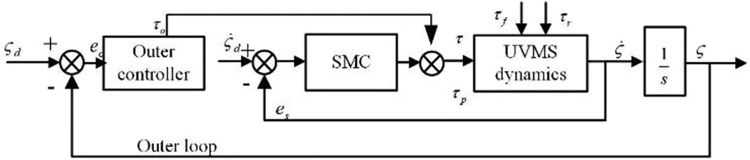
Outer-loop sliding mode control structure in task space.
Stability analysis
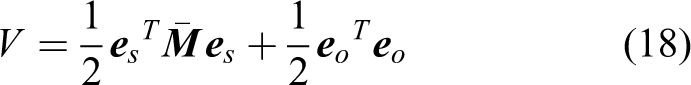
Further, we propose the Lyapunov-like positive definite function V as equation (18)
With the properties
23
of

Applying equation (16) to equation (17) yields

Using equations (14) and (20), equation (19) can be rewritten as
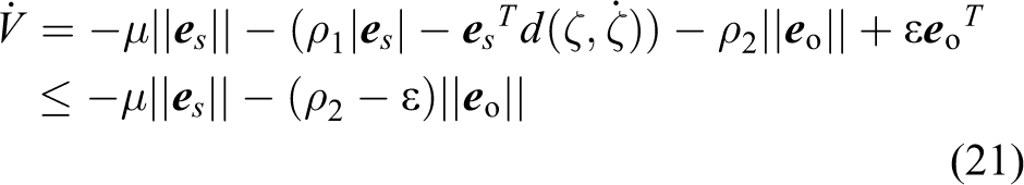
If and only if
Fuzzy multitask priority motion planning method
Given EE position/orientation, coordinated motion planning for joints and AUV body is required; secondly, this step is to execute the path planned through the control law reflecting in the joints and EE pose. Then, there exists an error between the desired and the actual pose, in which the designed controller eliminates. It is considered that the closed-loop form not only needs to combine dynamics and kinematics models but also designs a motion planning algorithm for multiple tasks.
When the EE position and orientation is desired, the motion of each joint and the AUV body will be planned in the general form

where
Combined dynamics and kinematics task priority motion planning method
The general form of the TP solution of equation (22) is as follows 13

where
The

where s is the total number of secondary tasks and
Combining equations (23) and (24), we obtain

It can be seen from equation (25) that
The prioritized task of UVMS is

Setting the EE position/orientation as the prioritized task when facing the UVMS motion planning problem. So, in this article, it meets the following condition:
Similarly, the secondary tasks

The motion planning algorithm, including secondary objectives, based on TP can be obtained by equations (25) to (27)

where

Combined dynamics and kinematics networked fuzzy task priority frame.
It can be seen from equation (28) that the prioritized and secondary tasks do not conflict, the secondary task requirements can be met simultaneously in the space of the prioritized task. However, when the two tasks conflict, it is necessary to ensure that the prioritized task is completed. When the position is obtained by integrating the velocity, it may cause a numerical drift problem. So, according to the dynamics–kinematics controller and equation (28), the closed-loop form is introduced

where
Based on equation (29), algorithm error of secondary tasks is zero when
Summly, the weighted TP with compensator, as shown in Figure 3 can be obtained,

where
Joint limit constraint and coordinated motion of underwater vehicle-manipulator systems
It is hoped that the AUV-body move with a minor pitch and the joints cannot exceed its mechanical limit. For example, the q2 should motion within
Specifically, a diagonal matrix
There are certain problems in restricting joint constraints only by the size of the defined
Introduce the norm When in the situation of Only in the situation of
This article mainly studies the motion planning of UVMS combining kinematics and dynamics. There is still a key point in this topic to realize the coordinated motion of the AUV and manipulator. 31 This question is of great significance to the total system. Under the TP framework in the task space, the EE posture is the prioritized task.
In equation (26), weighted matrix

UVMS contains two subsystems with different characteristics. The AUV system has large inertia and slow time-varying characteristics, while the manipulator system has the characteristics of small inertia and fast time-varying. For its different characteristics, it exists certain problems in equation (31), when

The weighted matrix in equation (30) can be written as the product of the weighted matrix with joint constraints and coordinated motion

The following discusses the characteristics of the
Exchangeability
Both
Free of singularity
The singularity of
Networked fuzzy logic for secondary tasks gains
“Combined dynamics and kinematics task priority motion planning method” and “Joint limit constraint and coordinated motion of underwater vehicle-manipulator systems” sections construct the UVMS multitask motion planning algorithm of equation (30). It can ensure EE’s control accuracy, simultaneously complete secondary tasks (avoiding joint limit, coordinated motion of AUV body and manipulator, etc.) in its null space. Sadly, it cannot effectively determine the weight of each secondary task. Fuzzy logic 6,11,19,20 and neural networks 9 are usually used to solve this problem. Fuzzy logic, as a higher-level supervisor, considers here. Simultaneously, based on fuzzy logic, 20 the logic is networked that how secondary tasks are allocated.
It is vital to avoid the joint limit when task execution, the distance to the joint limit is taken as the first secondary task

Holding the position and posture stability of the AUV body during underwater operations is important for UVMS coordinated control. Considering that the AUV pitch maps a significant effect for UVMS, it is taken as second secondary task in this article
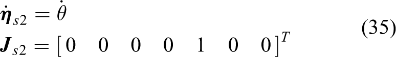
Here,
The abovementioned secondary tasks can be activated by fuzzifier with the three inputs (q2,q3,
Then, a networked fuzzy inference engine is constructed, based on the traditional fuzzy logic, 2 a hidden layer neural network is introduced into the fuzzy inference engine layer as shown in Figure 4. Through the neural layer, weights are shared to obtain more effective outputs. The neural layer is as the following

where

Networked fuzzy inference system, where the close and not close, respectively, represent the membership function close to and away from the joint bound. Small and not small, respectively, express small or large AUV-body pitch. AUV: autonomous underwater vehicle.
Networked fuzzy logic has the following advantages: (a) Compared with the simplified input-output relationship in Table 3, in this networked fuzzy logic, the output characteristics under each input’s combined action can be obtained, which compensate for the incompleteness of the former. (b) A more detailed fuzzy set can also solve the incompleteness mentioned in (a). It needs to subdivide the input and output rules, often reach more than 32. 2 Unlike this idea, networked fuzzy logic can guarantee the reconfigurability of fuzzy relationships by adjusting the weights, replacing artificial excessive constraints, and still achieving good flexibility and realizability.
Fuzzy logic 2 (.).

JL: joint limits; VA: vehicle attitude.
Simulation
Conditions
To verify the proposed method’s performance, simulations were achieved on an AUV, as given in Tables 1 and 2, with a 3-DOF manipulator 10 shown in Figure 1. The initial pose of EE is [−0.90 m, 0.70 m, 0 m, 139°, 0°, 90°]. It is worth noticing that this desired trajectory is part of a circle from [−0.90 m, 0.70 m, 0 m] to [−2.11 m, 1.10 m, 1.35 m]. The radius of this circle is 1.80 m. The center of the circle is located in [−2.60 m, 1.20 m, −0.36 m]. Based on this trajectory, the desired velocity of EE is adopted by the cubic spline. The simulation time is 30 s.
It is assumed that the model uncertainty for dynamic parameter is 10%,
10

Meanwhile, define the prioritized task is
The proposed motion plan method is compared with the pseudoinverse method, 2 which is given in equation (22). Besides, combining equation (31), the weighted pseudoinverse method is also used as a comparison. For simple representation, the proposed outer loop controller is termed case 1 (c1). The classic sliding mode controller is termed case 2 (c2). Hence, the proposed motion planning method based on the proposed dynamic controller is termed proposed planc1. The proposed motion planning method based on the classic SMC is termed proposed planc2. The pseudoinverse method and weighted pseudoinverse method based on the proposed dynamic controller are termed Pse planc1 and W-pse planc1, respectively.
Simulation results
The results are shown in Figures 5 to 11. It is assumed that the Pse planc1 and W-pse planc1 are free of singularity in this simulation condition.

The circular trajectory desired and simulated. (a) The attitude of UVMS in the proposed planc2 at 15 s and 30 s; (b) the attitude of UVMS in the Pse planc1 at 15 and 30 s; (c) the attitude of UVMS in the W-pse planc1 at 15 and 30 s; and (d) the attitude of UVMS in the proposed planc1 at 15 and 30 s. UVMS: underwater vehicle-manipulator system.

Errors when tracking the circular trajectory: (a)

The autonomous underwater vehicle velocity When tracking the circular trajectory. (a, b, c) Results from the vehicle linear velocity

The attitude of end-effector when tracking the circular trajectory.

The position of the underwater vehicle when tracking the circular trajectory. (a) The trajectory in

The attitude of the underwater vehicle when tracking the circular trajectory. (a) The trajectory in roll direction; (b) the trajectory in pitch direction; and (c) the trajectory in yaw direction.

The joint velocity desired when tracking the circular trajectory. (a) The velocity desired in joint
Figure 5 shows the circular trajectory desired and simulated. Given the desired EE trajectory as a circle with a radius of 1.80 m, the proposed planc2 failed to reach the endpoint at 30 s and the error up to 0.14 m. The proposed planc1 can track the desired trajectory well in the first 15 s, while the Pse planc1 and W-pse planc1 have better performance at this time. Figure 5 also shows the posture of the UVMS at 0, 15, and 30 s. Pse planc1 and W-pse planc1 have a larger pitch of AUV, as shown in Figure 5(a) and (b), the pitch at t = 15 s is 63.9° and 56.3°, respectively. The pitch at t = 30 s is 45.9 and 38.8, respectively. The angle in the roll and yaw directions under those two algorithms is very small, and the AUV still has the instability of pitch. In contrast, the proposed planc1 and proposed planc2 are largely in the yaw direction, and no more than 30°. As shown in Figure 5(c) and (d), the UVMS has attitude stability in the proposed planc1 and proposed planc2.
Figure 6 shows the error of EE in
What needs to be reviewed in this article is that the proposed planc1 and proposed planc2, under the frame of the TP, consider the stability of the AUV attitude as second secondary task. Figure 7 shows the velocity of AUV when tracking the circle trajectory. The velocity of the proposed planc1 and proposed planc2 in the
Based on pse planc1, a coordinated motion distribution
Figure 11 demonstrates the desired joint velocity when tracking the circular trajectory. The proposed planc1 and proposed planc2 are similar that
Figure 12 maps the energy consumption

The energy consumption
Conclusions
In this article, a combined dynamics and kinematics networked fuzzy TP motion planning method is proposed. The underwater vehicle’s posture stability and joint limits are mapped into the null space of EE’s trajectory in this proposed coordinated motion plan approach. An outer loop sliding mode controller is used for the EE’s trajectory tracking precisely. Simulation results show that the proposed planc1 achieves better coordinated motion planning of UVMS. It ensures the smaller angular displacement of AUV, not to exceed 30°. The redundancy of joints is taken fully considered in which a large displacement is used in q1 and x,y direction of AUV. However, the pse planc1 and W-pse planc1 are free of coordinated motion planning. Its pitch reaches 63.9° and 56.3°, respectively, which still affects the stability of AUV. Facing the external disturbance, the proposed planc1 has reduced desired joint velocity’s errors of 1.8%, 35.0%, and −2.3%, respectively, compared with the traditional SMC in proposed planc2. Furthermore, the errors at ze are reduced by 39.64%, respectively. The proposed planc2 failed to reach the endpoint, while the proposed planc1 has the smallest energy consumption. Even though the coordinated motion plan framework’s effectiveness was validated through simulations, experiments should be carried out to further enhance the simulation results, which will be done in the future.
Footnotes
Declaration of conflicting interests
The author(s) declared no potential conflicts of interest with respect to the research, authorship, and/or publication of this article.
Funding
The author(s) disclosed receipt of the following financial support for the research, authorship, and/or publication of this article: This work was supported by the Research and Development of Key Technologies and Equipment for Underwater Life Detection and Search and Rescue of China under grant number 2020YFC1512200.