
Abstract
To move out of the lab, service robots must reveal a proven robustness so they can be deployed in operational environments. This means that they should function steadily for long periods of time in real-world areas under uncertainty, without any human intervention, and exhibiting a mature technology readiness level. In this work, we describe an incremental methodology for the implementation of an innovative service robot, entirely developed from the outset, to monitor large indoor areas shared by humans and other obstacles. Focusing especially on the reliability of the fundamental localization system of the robot in the long term, we discuss all the incremental software and hardware features, design choices, and adjustments conducted, and show their impact on the performance of the robot in the real world, in three distinct 24-h long trials, with the ultimate goal of validating the proposed mobile robot solution for indoor monitoring.
Introduction
Numerous innovative mobile ground robots have been designed over the years. However, their capability to withstand long periods of operation is not always clear. Mobile robots manufactured by companies are typically subject to several thorough independent and integrated tests, which tend to delay and limit their availability in the market. In academia and more specifically in robotic labs, when robots are built and developed in-house, they are not always subject to intensive operational tests, and their robustness is often taken for granted, due to the limited duration of interactions or operation of the robots in most proof of concept research applications.
In this article, we describe an incremental methodology for the implementation of an innovative service robot for continuous indoor monitoring tasks in the realm of the STOP (Cooperative Robotic Securities) R&D project (http://stop.ingeniarius.pt). The methodology presented gain inspiration from the incremental model and spiral model for software engineering. The robot follows an incremental plan-design-implement-test-analyze cycle, identifying and handling risks as the development proceeds. 1
In brief, STOP is an industry-academia partnership project, which proposes the deployment of mobile robots in large human-populated indoor spaces, for example, shopping malls, airports, offices, museums, and so on, to carry out surveillance missions independently. 2 The main objective of STOP is to help human beings in the monotonous or repetitive tasks associated with the supervision, monitoring, and surveillance of infrastructures, which have low added value, and may ultimately pose a risk to human guards.
Security applications are a fundamental task with an unquestionable impact on society. Therefore, we focus on the design and development of the service robot platform and more specifically on the operation of the robot for extended periods in monitoring applications. To this end, we conduct a set of evaluation tests and adjustments to increase the robustness of the robot’s software and hardware through sensor fusion and an innovative localization architecture, grounded on the robot operating system (ROS) (http://www.ros.org). We show the impact of the proposed architecture and key software and hardware adjustments in the localization performance during 24-h continuous tests and validate the proposed service robot for indoor monitoring.
Related work
Notable pioneer mobile robots operating in human-populated dynamic environments include RHINO, 3 Xavier, 4 Mobot, 5 RoboX, 6 and Jinny. 7 These robots were designed to work for long periods of time yielding varying performance and leading to important lessons for the field of autonomous robots. Generally, the main challenges encountered were
maintaining accurate localization at all times, often resorting to artificial landmarks to correct the robot pose;
dependency on humans to make occasional modifications to the environment;
sensor limitations at close range;
unexpected collisions with dynamic obstacles;
navigation relying on off-board resources;
navigation limited to predefined movements in safe routes;
uncontemplated user intervention, for example, robot kidnapping or triggering emergency buttons;
hardware failures and software crashes, which underline the importance of more robust hardware and software architectures.
Most of the abovementioned robots already presented some degree of self-diagnosis of failures and were often able to ask humans to help them recover from such failures. Recent work dealing with robots for long-term human-populated environments has also addressed some level of self-repairing from failures. For instance, recovering from entrapment through navigation recovery behaviors is an interesting feature in the PR2 robot 8 from Willow Garage. According to the authors, which focused mainly on the navigation system: “existing approaches invariably require some modification of the environment or do not allow the robot to negotiate tight spaces.” To overcome this, they proposed a navigation system that includes 3D obstacle sensing using efficient voxel grids, and they subjected the PR2 to long endurance tests. The main limitations found in the study relate to avoiding small objects on the floor, below the threshold for the minimum obstacle height that sensors can detect, and speed and safety limitations imposed on the robot due to the usage of a tilting laser scanner to infer 3D space. Shifting the focus from task-level robustness to system-level robustness, the same group of researchers had the PR2 robot, conducting an ambitious 13-day uninterrupted run, navigating randomly between predefined points in an unmodified office environment, recharging itself when needed, and identifying failures, thus proposing a system architecture that supported recovery modes and involved both autonomous and human-aided recovery strategies. 9 The key lessons learned were
reliability can be increased at the levels of software engineering (divide complex processes into multiple smaller ones, store states externally to successfully recover crashed processes, killing and spawning processes on demand), autonomy (redundancy in algorithms, allow enough time to start recharging attempts, allow human-in-the-loop solutions), and environment (redundancy in the environment, e.g. multiple paths to the same location, multiple recharging locations, etc.);
uncovering and diagnosing failure cases can occur faster by devising tests to continuously run the failure components more often and for longer periods;
some critical failures, for example, kernel panics, hardware failures, electronics failures, and battery problems, do not have a realistic recovery strategy.
Projects dealing specifically with long-term autonomous service robots have been highly in vogue, receiving funding from the American National Science Foundation and the European Commission, such as CoBot 10 and spatio-temporal representations and activities for cognitive control in long-term scenarios (STRANDS), 11 to accelerate the deployment of such systems in the real world.
The CoBot robots follow a novel symbiotic autonomy, in which the robots are aware of their perceptual, physical, and reasoning limitations and proactively ask for help from humans, for example, for object manipulation actions, as the service robots do not have arms. The CoBots were able to overcome the 1000-km challenge proposed by the CMU research group to demonstrate the robustness and accuracy in localization over long-term deployments 10 in the presence of variations and changes in the environments. According to the authors, more than 93% of robot deployments did not require human intervention to reset the robot localization, and a monitoring script running on the robots would track the tasks’ execution progress and email researchers in the cases when the robots needed assistance.
In the STRANDS project, the focus was placed on enabling autonomous robotic operation in everyday environments and allowing the robots to use their long run times to improve their own performance. 11 The authors tackle the problem by requiring the hardware and software of the robot to be robust enough to overcome failures, providing design-time and run-time monitoring. The approach is based on understanding 3D space and how it changes over time, extracting spatio-temporal structure from long-term sensor data. This way, using a predictive model, the system’s robustness is improved by making the robot to avoid, for instance, areas, where it previously encountered navigation issues. Similarly, the robots were capable of learning models of normal human activity and then raise an alert if an observation deviated from this. Like CoBot, the STRANDS robots ask for help when they are not able to recover from an unexpected situation, for example, if the robot’s bumper is pressed, a hardware cut-off prevents it from moving forward, so the robot asks to be pushed away from obstructions by nearby humans.
Furthermore, resilient robots have been developed lately to allow recovering from failure states. However, the focus is usually placed on flying, 12 soft, 13 and self-reconfigurable robots. 14 In a recent survey, 15 it is mentioned that one of the main principles to design resilient robots is to follow a modular architecture, where all components have standard interfaces to interact with each other so that the modular system can easily be changed in terms of configuration. Nevertheless, the survey does not mention any wheeled mobile robot, showing that this type of design in most cases still lacks resilience when compared to other robot modalities.
The overall performance of a mobile robot is severely constrained by its fundamental localization system. Several advancements have been proposed in this domain over the years, from the early work of Drumheller, 16 to the proposal of Kalman filter-based techniques, 17 other Bayes filter variants, 18 Monte Carlo localization, 19 and associated variants. 20 In this work, we propose to improve the robustness of a service robot for continuous indoor monitoring, focusing not only on the hardware but also on the software and more specifically in the robust localization of the platform, which is based on the widely used adaptive Monte Carlo localization (AMCL) algorithm. 19 Let us now state the contributions of our work.
Statement of contributions
Proven autonomy is the ultimate achievement for many researchers in robotics. 9 This article presents work in progress in the context of the STOP R&D project 21 toward indoor long-term monitoring of infrastructures with a service robot. Accordingly, we propose the following key contributions:
The design of an innovative mobile service robot developed from the outset for continuous monitoring in large human-populated indoor spaces, with an affordable price tag, unlike most robots referred previously.
An incremental methodology for implementing, testing, and validating the proposed service robot through 24-h long trials with an in-depth discussion of results for performance improvement planning.
The proposal of robust and reliable hardware and software, namely a novel modular ROS-based localization architecture grounded on AMCL, sensor integration, and scan-matching techniques.
As seen before, we consider localization as a fundamental capability for a mobile robot engaged in a monitoring task. Localization is paramount for reliable navigation, perception, interaction, and generally operating in the environment to achieve a higher technology readiness level (TRL). We leave other relevant aspects, such as autonomous charging, detecting human actions, and changes in the environment, 22 deploying teams of cooperative robots, and so on, for future work within STOP.
In the next section, the base design of our service robot solution is presented, and in the next section, we describe the initial localization architecture used. Then, we run preliminary monitoring tests with the initial service robot architecture, and we report the main issues observed. The following section addresses the improvements on the localization and sensor integration within the software architecture of the robot, and later, we describe intermediate tests and validation. Subsequently, we propose enhancements on the robot hardware robustness to provide a stable version of the proposed mobile robotic solution, which is validated in final 24-h operational tests. The article finishes with conclusions and open issues for research, as part of the STOP R&D project’s objectives.
Innovative service robot for indoor monitoring
Over the past years, the private security sector in Europe has been growing, representing an annual turnover of about 35 billion euros, making this a market with the potential to be exploited in an innovative technological perspective. Security tasks are monotonous, repetitive, have low value-added for humans, and can be potentially dangerous in some scenarios, thus presenting a high potential for human agents to be replaced by robots.
Service robots available in the market face frequent issues that reduce their wide deployment, namely, they either lack the features and the necessary level of robustness for real-world time-consuming tasks or they are highly expensive and complex, such as the case of PR2 (PR2 is priced above $280,000 plus taxes and shipping: http://www.willowgarage.com/pages/pr2/order), or the renowned Fraunhofer’s Care-o-Bot series. 23
STOP envisages to deploy teams of affordable cooperative service robots for indoor monitoring below the $15,000 price tag per unit. Thus, unlike most previous works, we use inexpensive short-range sensors, and we focus on approaches that are robust to sensor limitations. Besides cost, other priorities in the design phase of the robots included: energy autonomy for at least 8 h of continuous operation, wireless communication abilities, appropriate sensing capabilities to perceive the environment, detect intruders and interact with humans, increased processing capabilities to handle all the system’s information, and ROS compatibility.
Design
As with any other electromechanical work, an emphasis is given to the design of the proposed robot. The computer-aided design has been divided into two distinct phases: external structure and internal structure. Figure 1 shows the external structure of the robot. It illustrates the final robot appearance, and how the robot shell is placed on top of the internal structure, covering its interior. Figure 2 shows the design of the robot internal structure, which consists of an aluminum base connecting the differential drive system with two traction wheels, two caster wheels, two LiFePO4 batteries, supports for the light detection and ranging (LiDAR) sensor, infrared sensors, the main central processing unit (CPU), microcontroller, and all other electronics.

(a–c) Design of the robot external structure.

A closer look at the STOP mobile robot’s internal structure and hardware components: (a) Upper part components, (b) top view of the base components, and (c) bottom view of the base components.
Hardware components
The robot structure is supported by a combination of aluminum rails and polylactic acid (PLA) 3D printed modules.
The upper part of the robot (see Figure 2(a)), comprises a waveshare 10.1″, 1280 × 800, LCD touchscreen for human–robot interaction (HRI), an Orbbec Astra RGB-depth camera for obstacle detection and identification of humans, objects, and abnormal situations, and a Wi-Fi dongle, the Alfa Wireless Adapter AWUS036AC, to allow the connection with the local Wi-Fi communication infrastructure, serving as the main communication channel with the project’s server and eventually other teammates. These three components are physically connected to the main computing unit of the robot, the Intel NUC 6i5SYK PC, via USB.
Figure 2(b) shows a top view of the base of the robot, wherein one can identify in the center the RPLIDAR A2 laser range finder for localization, navigation, and mapping, with a 360° field-of-view and a maximum range of 12 m. The base also entails two Pololu infrared sensors in the front, Logitech Z120 stereo speakers in the back, a pair of black polyurethane traction wheels with 144 mm (5.7″) in diameter and 29 mm (1.2″) in width, with 12 V brushed DC motors with a 131.25:1 metal gearbox and an integrated quadrature encoder, corresponding to 8400 counts per revolution of the gearbox’s output shaft. Moreover, a printed circuit board was conceived and included in the base, with the electronic circuit for the OMNI-3MD motor controller board (http://botnroll.com/omni3md_en/), and the particle photon microcontroller for low-level robot control, which interconnect via I2C. A piezoelectric buzzer at 3.4 kHz is connected to the microcontroller, allowing for robot sound notifications.
The robot base also includes an emergency button for safety and testing, cutting the motors’ power as soon as it is pressed. This is only accessible during the development stage. A pair of two lithium LiFePO4 12V/20 Ah batteries provides power to all platform components.
At last, Figure 2(c) shows the bottom view of the base of the robot, illustrating the CPU of the robot, the Intel NUC 6i5SYK PC, equipped with 8 GB of RAM and a 256 GB solid-state disk. The NUC PC connects to the particle photon microcontroller for low-level data exchange, and to most other components, such as the RPLIDAR A2 and the stereo speakers via USB. The figure also illustrates the two caster wheels of the robot, and the robot base also includes an on/off switch to start the robot, which requires a specific physical key.
Low-level communication and middleware
The STOP robot follows a hierarchical software architecture. At the lower level, the OMNI-3MD driver motor controller board allows direct actuation commands to the robot’s wheels with differential drive PID control and provides encoder readings to keep track of the robot’s ego-motion. The particle photon is the main mid-level component, carrying an STM32F205 120 MHz ARM cortex M3, a 1 MB Flash, 128 kB of RAM, interface with 18 mixed-signal GPIO and advanced peripherals, and a Cypress Wi-Fi chip. It deals with motion control and kinematics, exposing relevant information to the higher level, such as odometry calculation from encoder readings, battery status, infrared distance sensor readings, sending an independent Wi-Fi keepalive low-level security beacon, receiving velocity commands and forwarding them to the robot base, and converting the low-level data in appropriate ROS message structures through

Low-level communication in the STOP robot.
The Intel NUC CPU incorporated in the robot runs the ROS, the main framework that is utilized to control the mobile robot on Ubuntu Linux. Specifically, the PC connects to the RPLidar A2 laser range scanner and the Orbbec Astra camera via USB, retrieving information from these sensors using appropriate ROS drivers. Moreover, the PC provides access to the sound speakers and the tablet interface for HRI. The robot high-level software (localization, navigation, patrolling, human detection, planning, decision-making, communications, etc.) is developed on ROS, running on the PC, being fed by sensor information, and acquired by the developed drivers.
As such, the robot is fully ROS compatible, and several packages have been developed to provide basic functionality, such as access to readings from all sensors, laser self-filtering to clear the robot structural points from laser readings, point cloud obstacle detection, navigation and recovery behaviors, robot teleoperation, and visualization.
Initial localization architecture
With the increased use of common robotics middlewares, such as ROS and their tools, several research groups have turned their focus to particular and relevant high-level scientific goals and applications scenarios, dealing with the underlying issues, for example, localization, navigation, and so on, by making use of the recognized and proven algorithms integrated by the robotics community.
For our case of mobile robots monitoring indoor environments, the initial localization system is depicted in Figure 4.

Initial localization architecture.
The localization approach, which we deem as Standard AMCL (AMCL stands for the adaptive Monte Carlo localization method), makes use of a 2D occupancy grid map representation, which can be derived from a simultaneous localization and mapping (SLAM) algorithm 24 ran previously in the indoor area where the robot operates. Briefly, this probabilistic localization system receives the odometry estimates of the robot and laser scan readings and uses a particle filter to track the planar pose of the robot (x, y, θ) against the known map to output the most likely robot localization in the map.
Our ROS driver running at the lower level in the photon microcontroller reads the encoders ticks from the motors and calculates the odometry values, considering the differential drive wheels of the robot. These values are sent at 10 Hz through serial communication to the AMCL node. The AMCL node is also fed with the static occupancy grid map of the environment as well as the updated laser scans coming from the LiDAR of the robot at 10 Hz. By processing all this information, the AMCL node outputs the most likely localization of the robot by publishing a ROS transform also at 10 Hz.
The ROS implementation of the AMCL is open source (http://wiki.ros.org/amcl), and for more details on the method, one should refer to the literature. 19
Preliminary monitoring tests
This section describes the preparation and unwind of the first continuous monitoring tests of the STOP project. We aim at testing the service robot developed at the initial stages of the project, validating its basic functional features, such as the robot hardware and the implemented controllers, especially the robot localization. Despite not being the focus of the work presented, the tests also allow to generally validate the robot’s energetic autonomy, wireless communications, and the trajectory planning and navigation methods in human-populated environments.
Preliminary simulation tests, as well as hybrid simulation and real-world short-term tests have been previously reported in the literature. 25 In contrast, the monitoring tests presented here consist of a 24-h long trial with the service robot developed, which is continuously traveling autonomously on the third floor of a technology center building (The tests took place in the CTCV building in Coimbra, Portugal, see https://goo.gl/maps/Ts3XB3p6VazhuLfT7), following the mobile robot patrolling approach presented in the literature. 26,27
As a preparation for the prototype demonstration, a Wi-Fi communication infrastructure was deployed for full coverage of the area where the robot operates. The infrastructure is composed of three wall-mounted Wi-Fi antennas (802.11 ac) with dual radio access points. These dual-band antennas make use of 802.11 a/b/g/n/ac Wi-Fi standards and WEP, WPA-PSK, and WPA-enterprise (WPA/ WPA2, TKIP/AES) wireless security. For this Wi-Fi network, a specific virtual local area network has been configured to isolate it from other private and public networks in the building.
Signs were placed near the building stairs to protect the robot, avoiding falls, and allowing people to easily acknowledge the trial operations. Figure 5 shows the trial site, with pictures of the robot navigating in the environment during the tests.

Pictures of the monitored test site during the preliminary tests of the project. Note that the pictures’ viewpoint are signaled in the map of the environment.
Using the hardware and controllers described previously, the robot was tasked to run several ROS nodes during the demonstration. Besides the standard AMCL approach for localization discussed in the previous section, which uses the known map of Figure 5, the robot executed the needed ROS drivers to get information from all sensors (laser range finder, RGBD camera, etc.) in real time.
Furthermore, the ROS navigation software based on the literature 8 was employed. The software takes in a navigation goal sent by the patrolling node, data from sensors, and localization information, and sends appropriate velocity commands to the mobile robot base. It includes global planning capabilities using A* and obstacle avoidance via a local dynamic cost map. In addition to this, we used the patrolling software from a previous work, which takes in the system’s monitoring state as well as all the important places that need to be covered by the robot in the environment in the form of a graph (see Figure 6), probabilistically computing the next place that should be visited by the robot.

Graph of the environment. Blue dots correspond to the vertices, which need to be visited by the robot and red lines correspond to the edges that connect nearby vertices.
Moreover, we developed a node that detects localization “jumps.” These occur when AMCL fails to localize the robot, increasing the number of particles in the filter adaptively, thereafter resampling a more likely global position for the robot, far from the current one. As such, when there are large gaps between the previous and current position estimation, it means that a localization “jump” has occurred, and this node will warn the user by activating the robot buzzer and asking for manual relocalization. Note that in precise localization systems, these jumps are not meant to occur.
Finally, relevant data from all levels of the robot software architecture were recorded during the trial, using the
For the 24-h trial, several collaborators took turns to oversee and guarantee the continuous operation of the robot in the environment, taking actions only when absolutely necessary, for example, to relocalize the robot or to recharge its batteries when needed. The only concern at the beginning of the trial is to correctly feed the initial pose (x, y, θ) of the robot to the localization system (AMCL node), and the system would then run the monitoring mission autonomously, consecutively visiting all important points of the environment while recording datasets and logs for a posteriori analysis.
Discussion and observed issues
A video of the experiments running at 60 times faster than real time is available at https://tinyurl.com/y5lp8oux, and in Figure 7, we illustrate the robot’s position in the map, laser sensor readings, recent positional data, the battery and Wi-Fi connectivity state, and the onboard camera image in the ROS visualization software,

Robot monitoring the test site during the preliminary test.
The robot was able to generally carry out the monitoring demo, safely navigating within the environment, avoiding obstacles, and correctly planning its trajectories, while being localized 85% of the time. The robot operated continuously for at least 8-h intervals and needed around 1 h and 45 min for a full recharging cycle.
Figure 8 shows an overview of the results collected during the 24-h trial. One of the most important aspects of this experiment is the proliferation of localization issues as time goes by (first bar in Figure 8). So many localization issues during the trial were not expected, possibly because such an intensive test was never conducted previously with the robot. Interestingly enough, during the first hour of experiments, no localization failure was reported, and toward the end of the 24-h experiment, these failures became constant. The robot spent a total of almost 3 hours’ time with localization issues for diverse reasons, which we dissect below. As a consequence, a total of eight independent collisions with obstacles occurred during the experiment (second bar in Figure 8).

Overview of the 24-h long preliminary experiment. Video available at https://tinyurl.com/y5lp8oux (60 × faster).
A more detailed analysis of these results allows to identify occasional and possibly interrelated factors that may explain the localization issues that occurred during the experiments. Below, we attempted at identifying and clarifying them, posing some hypothesis to be addressed in further tests:
Wheels became loose after a long period of operation (visually confirmed + distinctive noise): The wheels of the robots tend to become loose over time. Permanent wheel tightening is necessary to correct this, as it highly impacts the motion of the robot and provides additional errors to odometry calculation.
Worn gears (visually confirmed + loud noise after a long period of operation): When the robot resumed patrolling after recharging for the second time (3 h 30 min before the end of the experiment), a very loud constant noise from the gears was noticeable. The gears became worn and were not functioning at maximum performance, which, together with loose wheels, may explain the increase of localization issues toward the end of the experiment.
Robot driver block (confirmed by the dataset and log results): Logs show that the data coming from the robot driver from the low level are not always consistent. There are sporadic encoder jumps, the odometry is not always up-to-date, and the control rate acquired from the OMNI board sometimes provides inconsistent values.
Poor odometry estimation while turning (hypothesis by analyzing sensor data and position estimation): Most localization errors occur during rotations. Loose wheels, worn gears, and driver blocks may explain most issues. However, further tests need to be made to understand if the positional estimate of the odometry is accurate when none of the above conditions happen.
Lack of features in laser data for localization (hypothesis due to a positional jump when a large group of people were around the robot): If the laser sensor is severely obstructed, the localization software will not always be able to match features against the known map. People around the robot and severe map changes may cause this. It may be important to further test and increase the robustness against these situations.
While two of the factors mentioned are purely hypothesis (factors 4 and 5), which need further testing to analyze their impact on localization, the first three factors have been confirmed and need to be carefully considered in upcoming tests.
When the wheels become loose, they propagate a large amount of error to the odometry, as they are not steadily rotating. It also represents a dangerous situation to the robot, which at any time may face a wheel withdrawal with unexpected consequences. Thus, it is necessary to find a solution to permanently fix the wheels in a stable position. Moreover, loose wheels seem to have led to some indefinite drifting situations, which are highly undesired, as the odometry tracks encoder ticks that do not correspond to actual robot movement, feeding the localization system with erroneous data, and leading to mislocalization, requiring human assistance to be solved.
In addition, the gears became fully worn after 20 h of experiment, which was completely unexpected. By the end of the experiment, a constant loud noise from the gearing system could be heard at distance. At the first stage, we hope that permanent wheel tightening will mitigate this issue, and ultimately, we consider the replacement of the gear system as a plan B.
Sporadic blocks on the data coming from the robot firmware were identified. This may point to issues on several sides (omni driver blocking, particle photon with interrupted access to the low level,
It is also not clear, due to the existence of several localization issues in the test, if the estimated orientation angle given by the odometry computation is precise. In the upcoming section, we provide means for assessing this by integrating a digital compass in the robot.
Finally, most robots worldwide use AMCL for localization and it is known to be extremely stable in indoor environments. Estimation errors and “jumps” in localization are more likely to occur due to poor input, for example, erroneous odometry estimates or sensor noise, than to poor performance of AMCL. Still, another possible factor that affects the odometry estimates is the lack of laser features in some situations, such as having too many people around the robot, or map changes. This is an open scientific problem in robot localization, and even though acquiring additional sensing hardware for localization would become too costly, one possible solution to this would be to provide a more accurate static map, consistent with all static objects (and removing any dynamic objects from the static map).
During the development of the STOP robotic platforms for indoor monitoring and surveillance, the standard AMCL was the initial localization system adopted. As expected, it proved to be a generally appropriate approach, especially in short-term experiments. However, for longer runs, we felt the need to propose a more robust localization architecture to guarantee that our robots can be precisely localized at all times and recover in case of unexpected situation. Table 1 clarifies the rationale behind our decision: the cons column justifies proposing changes to the standard AMCL system’s localization architecture, and the pros column shows that the advantages of AMCL are immense, and it is highly desirable to still guarantee these benefits. For this reason, in the following subsection, we propose a new and more reliable localization architecture based on AMCL.
Standard AMCL: pros and cons.

AMCL: adaptive Monte Carlo localization.
Software improvements and sensor integration
The preliminary demonstration reported in the previous section allowed to validate the basic functional features of the robot developed and plan subsequent adjustments. In the aftermath of the tests, several improvements have been proposed to the robot and its localization architecture in particular to overcome the phenomena previously observed.
Regarding the wheels and gears (factors 1 and 2), permanent tightening was guaranteed by piercing the transmission of motors and screwing them directly with a new set of similar gearboxes. This allowed to keep the same low-cost configuration as before, simply adding a new lathe machine operation to the electromechanical development of the robot. These modifications were tested accordingly after the preliminary trial to avoid the occurrence of loose wheels and worn gears during the tests.
Furthermore, as pointed out in the literature,
9
hardware failures rarely have a realistic recovery strategy. Thus, it is crucial that robotic software architectures are aware of hardware limitations to minimize their impact on system functionality. As opposed to what has been identified by factor 3, in the initial localization architecture, we assumed that the low-level readings from the OMNI-3MD power board were always consistent. As such, we would estimate the robot odometry at the low level by analyzing incoming encoder readings at 10 Hz. As such, the odometry pose estimation would be broadcast in the form of a ROS transform (

Proposed localization architecture. Text, arrows and boxes in red mark the changes in relation to the initial localization architecture of Figure 4.
Regarding hypothesis 4, we have integrated a digital compass in the mobile robot, as previously mentioned. The CMPS11 tilt-compensated compass readings are acquired at the low-level
As for hypothesis 5 on lack of features, not only do we mitigate this through the fused odometry mentioned above, which is expected to improve precision at the AMCL entry point, but we also leverage the fact that AMCL allows filter re-initialization at any time with a new pose. Therefore, we use the Snap Map ICP technique (The implementation of Snap Map ICP for ROS can be found in the following link: https://github.com/davidbsp/snap_map_icp/) to re-initialize the filter automatically by computing the fitness of the current AMCL estimated pose against the existing map and adjust (i.e. snap) the pose correctly to the map. For this, the component compares the laser readings with the occupancy grid map in locations around the current pose reported by the robot and uses the iterative closest point method 29 to estimate the most likely pose transformation based on singular value decomposition. When the match quality is above a certain threshold, the component triggers a pose re-initialization of the filter, preventing the robot to lose track of its pose.
All software improvements and the digital compass integration are shown in Figure 9.
Intermediate monitoring tests
Following the improvements described in the previous section, a new 24-h long trial started in the same technology center building environment, under similar conditions to those described in the first test. The software modifications done after the initial trial were integrated within the ROS middleware, and the robot, which is shown in Figure 10, was tasked to run the long-lasting monitoring mission autonomously. During this intermediate test, the robot recorded log data for proper in-depth analysis of results.
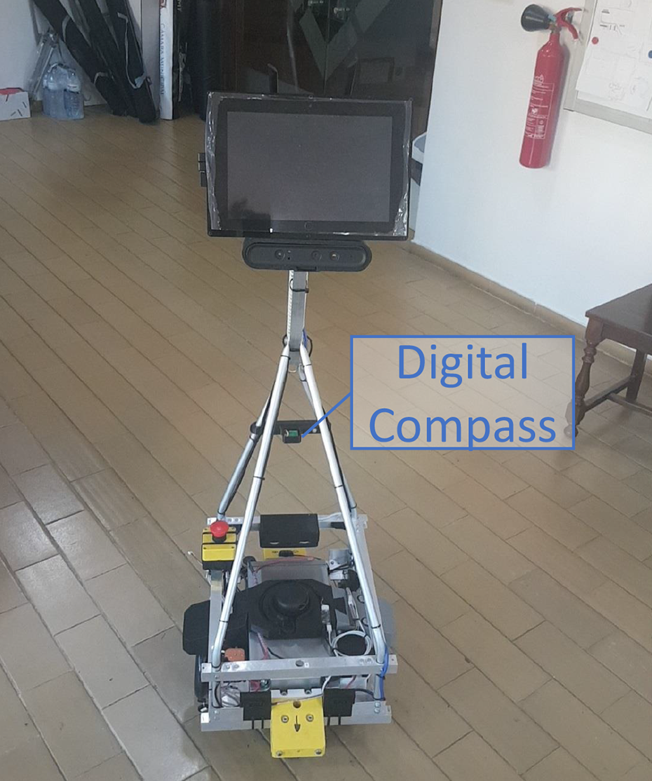
Proposed service robot after the integration of the digital compass.
A video of the experiments running at 60 times faster than real time is available at https://tinyurl.com/y3jlehw7, and in Figure 11, we provide an overview of the results collected during the 24-h trial. Once again, the robot operated continuously for at least 8-h intervals, and its two charging cycles during the 24-h experimental period lasted around 1 h and 45 min.

Overview of the 24-h long intermediate experiment. Video available at https://tinyurl.com/y3jlehw7 (60 × faster).
One of the most important aspects of this experiment is the correction of most localization issues when compared to the first test. During the whole run, we only had one mislocalization situation, as seen in the first bar. Fortunately, we were able to understand the cause of the issue after a detailed analysis of the logged robot data.
The localization issue occurs at around minute 10:40 of the above-referenced video. The hector SLAM node ran into a known problem (singular value decomposition) on a quick and sharp robot turn, in which the scan matching estimate led to a high angular difference from the prior pose estimate. This, in turn, led to a rare and unexpected interruption of the hector SLAM node, which was promptly respawned by our system automatically. However, when respawning occurred, the estimated pose was set to the origin of the hector SLAM frame of reference. This generated a discrete jump on the robot odometry estimation, which was propagated all the way up to our modified localization system (see Figure 9), resulting in a wrong global pose estimate. Therefore, the robot had to be manually localized, at minute 10:43 of the video, to recover and carry on the mission.
The integration of the digital compass and the software improvements resulted in a test with a clearly superior localization performance. The localization system is now aware of the limitations of the robot hardware and is able to filter out erroneous encoder data and fuse the odometry from different and redundant sources (encoders, digital compass, and HectorSLAM) to feed the AMCL with more accurate odometry data. Moreover, the occasional automatic re-initialization of the localization filter (Snap Map ICP) does not allow errors from more complicated slippage situations to propagate. The success of the test provided an initial validation of the localization architecture, showcasing its reliability and potential.
Another significant result extracted from this intermediate test is the lack of collisions with the environment, which is tightly related to the reduced number of localization faults when compared to the preliminary test with the standard AMCL architecture. Indeed, the modifications and improvements to the robotic system prior to the beginning of this test have properly handled factors 1–3 and hypotheses 4–5 identified when the preliminary tests were analyzed.
Still, similar to the initial monitoring test, at some points of the experiment (see for example minute 4:29– 4:53), even though localized at all times, the robot drifted endlessly in the same position and needed human assistance, that is, a “push” to break free. We were expecting this to be solved with the permanent wheel tightening and gears’ replacement, which occurred before the test. However, this was not the case, therefore a new factor was identified:
6. Sliding wheels (visually confirmed): The wheels slide in some areas of the environment leading to indefinite drifting, especially after the floor has been cleaned recently, and when the robot rotates over its own axis. The robot localization system at software level has shown to be robust to this. However, a hardware-level solution is needed to avoid human assistance.
In the next section, we describe our final improvements to the service robot for indoor monitoring, by directly addressing the remaining existing issues.
Hardware improvements
The cause of the single localization error that occurred during the intermediate trial was identified, and it was quickly fixed by checking if the hector SLAM node has restarted, ignoring its initial contribution to the odometry estimation, therefore avoiding discrete jumps. Nevertheless, this time the main changes to tackle the persistent issue of sliding wheels cannot be realistically solved at software level.
Software improvements have the potential to reduce the impact of hardware anomalies up to some extent, for example, looser wheels after long periods of operation or the progressive wear of gears, thus allowing the system to be more robust. However, the robot still gets trapped and slips indefinitely with these wheels. Wheel slippage is an issue that must be corrected either by increasing friction, guaranteeing that the four wheels touch the ground at all times, reducing from two caster wheels to just one (eventually sacrificing robot stability), or replacing the type of wheels in the robot.
Since the polyurethane wheels proved to be unsuitable to navigate in the environment’s ceramic floor and multiple slippages of the robot were observed, we added a spring-loaded gate to the caster wheels and replaced the existing driving wheels with rubber wheels with a larger surface of contact to increase the friction and avoid sliding situations. Due to the incompatibility between the wheel and gearbox connectors, further motivated by the noisy nature of the gearbox, this also led to the replacement of the whole driving kit (motor, gearbox, and wheel), with a low noise 12 V DC motor, which is much quieter than the original ones, and we expect these to overcome the occasional indefinite drifting issue.
Despite the aforementioned benefits of the new driving kit, the integrated quadrature encoders provide 2652 counts per revolution of the gearbox’s output shaft, against the 8400 of the original polyurethane wheels. Yet, we do not foresee this lower resolution to be critical for localization, due to the increased robustness of the localization architecture proposed.
Final monitoring tests
To test the modifications to the system described in the preceding section, a final 24-hexperimental trial was conducted under similar conditions to the two experimental tests that were previously reported.
Figure 12 shows an overview of the final experiment, and a video running at 60 times faster than real time is available at https://tinyurl.com/y67yv5xv. Results show a trial without manual pose re-initializations, and no permanent localization failures at all, as can be seen in the video of the experiment. With the new wheel kit, the robot does not get trapped anymore in the deployment scenario used for the prototypes, and the new gears did not become worn after the experiment. Moreover, no collisions were reported during the 24-h final test.

Overview of the 24-h long final experiment. Video available at https://tinyurl.com/y67yv5xv (60 × faster).
Another interesting result, which is directly linked to hypothesis 5, is the robustness of the proposed localization system even when several people were around the robot, severely obstructing the rotating 360° laser range finder. The robot is able to remain localized in densely human-populated areas, despite occasional disturbance and localization drifts, which were overcome by the system automatically. This is visible for instance around minute 14:35 on the video of the experiment, during an event that occurred at the technology center.
The incremental approach described in this article clearly shows a progressive improvement of the robustness of the service robot localization architecture in continuous indoor monitoring trials. Moreover, all three tests allowed us to validate a few other important aspects.
The Wi-Fi connectivity proved to be very persistent and resilient since only small failures were reported, the accumulated downtime resulted in an average of 25 s per 24-htrial. This allowed us to remotely connect to the robot during the trials via SSH to inspect the internal state of the robot, as well as monitoring the position of the robot in the environment, the camera feed, the laser scans, Wi-Fi connectivity, and battery state in real time using a different machine within the same network.
When designing the robot, the expected energetic autonomy provided was 8 h. Apparently, the results of all trials show that the autonomy is slightly above the expected range. In fact, the minimum continuous operation time observed was 8 h 11 min and the maximum was 9 h 32 min.
Conclusions and future work
In this article, we have proposed a novel design for a service robot for indoor monitoring tasks, and an innovative, reliable, and robust localization architecture, following a paradigm of software aware of hardware limitations. The localization system benefits from sensor integration and laser scan matching, being grounded on AMCL to accurately localize the mobile robot in large indoor facilities. The system was validated through an incremental methodology, in which three lengthy trials were performed, comprising progressive modifications that explicitly deal with the issues observed. This serves as a first step to propose a service robot with a long life cycle and a high mean time between failures (MTBF) so as to attain high TRL levels.
During the experimental trials to validate the system, manual actions were kept to the minimum, limited only to re-localize the robot whenever lost, pushing it in indefinite sliding situations, and to recharge its batteries, since the autonomous charging system of the project was not yet ready at this early stage of the project. A detailed analysis of results allowed us to identify the main factors to improve for subsequent trials up to the point when we were able to have a continuous test without any localization issues.
This work follows a current literature tendency as sensor fusion techniques become more popular lately, for example, see the literature 30,31 due not only to their performance but also to the increase of computation power in common machines.
The next step in the context of the STOP R&D project includes finalizing the robot shell for protection of its interior components and a more appealing presentation (see Figure 1(c)) and finalizing the assembly of the docking stations for autonomous recharging. On the software side, we would like to fine tune the navigation to swiftly handle situations when the robot is in tight spots while maintaining safety. Moreover, we will also include a more advanced artificial perception layer on the robot to detect anomalies in the scenarios, such as missing objects (e.g. fire extinguishers), modified object states (e.g. opened doors or windows), or tracking people during postwork periods. We are also working on a high-level decision-making system, allowing the robot to autonomously change its state according to external transitions, for instance, between monitoring, charging, tracking/following people, and teleoperation.
The service robot will be replicated and the system will be extended to a team of three mobile robotic units. A web-based graphical user interface will be developed to supervise the multirobot system, and we intend to run longer (>24 h) tests to evaluate the robustness and reliability of the system. Finally, due to the sensitivity of the data acquired in surveillance missions, we have been also making efforts to secure all communications of the system 32 to avoid exposing critical information.
Footnotes
Declaration of conflicting interests
The author(s) declared no potential conflicts of interest with respect to the research, authorship, and/or publication of this article.
Funding
The author(s) disclosed the receipt of the following financial support for the research, authorship, and/or publication of this article: This work was supported by the