
Abstract
Vision-based grasping plays an important role in the robot providing better services. It is still challenging under disturbed scenes, where the target object cannot be directly grasped constrained by the interferences from other objects. In this article, a robotic grasping approach with firstly moving the interference objects is proposed based on elliptical cone-based potential fields. Single-shot multibox detector (SSD) is adopted to detect objects, and considering the scene complexity, Euclidean cluster is also employed to obtain the objects without being trained by SSD. And then, we acquire the vertical projection of the point cloud for each object. Considering that different objects have different shapes with respective orientation, the vertical projection is executed along its major axis acquired by the principal component analysis. On this basis, the minimum projected envelope rectangle of each object is obtained. To construct continuous potential field functions, an elliptical-based functional representation is introduced due to the better matching degree of the ellipse with the envelope rectangle among continuous closed convex curves. Guided by the design principles, including continuity, same-eccentricity equivalence, and monotonicity, the potential fields based on elliptical cone are designed. The current interference object to be grasped generates an attractive field, whereas other objects correspond to repulsive ones, and their resultant field is used to solve the best placement of the current interference object. The effectiveness of the proposed approach is verified by experiments.
Introduction
With the rapid development of artificial intelligence, robots are more expected in our daily lives. They are required to operate in complex environments with different assignments. 1 –3 To accomplish the given task, the robot has to interact with the environment, where autonomous grasping is an important aspect. With this capability, the robot can provide better services.
In robotic grasping, the grasp detection can be determined directly on the point clouds. 4,5 Zapata-Impata et al. presented a method to find the best pair of grasping points given a three-dimensional point cloud for an unknown object, where a set of geometric rules is employed to explore the cloud. 4 Considering the raw incomplete 3D point cloud, Gori et al. first reconstruct the object in 3D and then obtain candidate triplets using discrete particle swarm optimization for three-finger manipulation. Finally, the best grasp triplet is selected. 5 Suzuki and Oka presented a method for untrained objects with a single depth image. 6 The planar surface and the object are extracted by employing random sample consensus (RANSAC), and the robot grasps the object along the principal axis obtained by principal component analysis (PCA). Such solutions are suitable for untrained objects in some tasks, such as table clearing, and they cannot handle the specific object due to the indiscrimination of point clouds. To solve this problem, the object detection provides a preferable scheme.
For object detection, visual perception is commonly used. Traditionally, the robot can use the depth and appearance features to recognize an object. 7,8 The detection accuracy may be affected by illumination variations. With the development of deep learning, researchers have proposed abundant deep networks. The representative methods include two-stage faster regions with convolutional neural networks (Faster R-CNN), 9 single-stage You Only Look Once (YOLO), 10 and single-shot multibox detector (SSD). 11 SSD discretizes the output space of bounding boxes into a set of default boxes over different aspect ratios and scales per feature map location, which possesses competitive accuracy with a fast processing. On the basis of object detection, grasp detection is then executed. A grasp detection solution is the model-based method. Morales et al. determined the best grasp based on a global model database that contains computer-aided design object models and grasp set for each object. 12 However, the construction process is time consuming. Asif et al. 13 presented a framework of hierarchical cascaded forests with CNN features to perform object recognition and grasp detection with RGB-D images. Chao et al. applied direct predictor and multimodal grasp predictor to obtain the best graspable region, where faster R-CNN and SSD are used to locate the grasp objects. 14 Chu et al. proposed a deep learning architecture to predict grasps for robotic manipulation, and the learning problem is defined to be classified with null hypothesis competition instead of regression, the deep neural network can predict multiple grasp candidates of multiple objects. 15 These methods mainly concentrate on the grasp detection of the target object and the influence of other objects on the target is seldom considered.
Actually, in everyday life environments, the scenes tend to be complex. Nevertheless, the robot should grasp the target object with the consideration of other objects. Kuehnle et al. proposed a collision-free method to grasp objects in the presence of obstacles, where each object is constructed by a 3D scale-invariant feature transform (SIFT) model. 16 A problem is its computation burden of scene model updating. Berenson et al. presented a framework to find valid grasps in cluttered environments, which consider the robot kinematics, the local environment around the object as well as the grasp force-closure quality. 17 Nagata et al. found a grasp point with grasp evaluation using geometric information about the target object with a 3D environment model around it by stereo vision. After the target object is assigned by the user, the user also determines its category from a list of the object models and selects the grasp mode from the corresponding list in sequence on the monitor. 18 For these methods, they tend to no solution in disturbed scenes, where there exist interference objects, which severely affect the grasping and the target cannot be directly grasped. Some pioneering works have been proposed to handle the grasping under disturbed scenes. 19 –21
Dogar and Srinivasa presented a push-grasp planner, which can push the target object away from clutter. 19 The object is pushed using a robot finger, and the capture region is introduced to enable the object roll into the robot hand. An assumption is that the pressure distribution is at the object’s periphery. Also, this method has a critical requirement of the contact point on the object for the finger, and an improper contact point shall lead to that the object deviates out of the hand. Different from the above push-grasp scheme, manipulating the interference object away from the target object provides another choice. Stilman et al. presented a resolve spatial constraint (RSC) algorithm for manipulation planning, 20 where the placement of an interference object is determined from feasible sampled placements in a probabilistic way. The larger the area of a region without objects is, the higher the chosen probability of sampled placements in the region is. The aforementioned placement scheme neglects the energy consumption of the manipulator and sometimes the interference object is placed at a farther position. The evaluation of placements still needs to be further improved. Zhao et al. proposed to move the interference object, whose best placement is determined based on artificial potential field. 21 One drawback is that the object pose is not considered. The object is non-inclined and it is expressed by a projected envelope rectangle on the table plane, whose two neighboring sides are coincident with Xw axis and Yw axis of the base coordinate system OwXwYwZw of the robot. Actually, the object can be placed in an arbitrary orientation, and the adaptability of this method to the object with an arbitrary orientation is poor. How to better select the placement of the interference object is still a challenge.
To achieve the matching of projected envelope rectangle and object pose, a natural solution is to generate an inclined projected envelope rectangle along the object orientation. However, it is difficult to express this projected envelope rectangle in a form of equation, and thus, the corresponding artificial potential field has to be discretely represented. This discretization in the inclined state brings in a computation burden, especially for fine-grained fields. A nondiscretized functional representation becomes crucial. In this article, a circumscribed ellipse corresponding to the minimum projected envelope rectangle is designed due to its small occupation space among the continuous closed convex curves. Then, the design principles of the potential field are presented, and they include continuity, same-eccentricity equivalence, and monotonicity. Guided by these principles, the elliptical cone is introduced and the attractive and repulsive potential field functions are then constructed according to different object types: current interference object to be grasped and other objects. Finally, the resultant potential field is acquired to determine the best placement of the current interference object.
This article is organized as follows. The problem statement is first given. Then, an object grasping method based on elliptical cone potential field model is presented. The effectiveness of the proposed method is verified by experiments.
Problem statement
This article is motivated by the robotic grasping under disturbed scenes, where the target object cannot be grasped directly and we focus on the moving of interference objects by the manipulator. Figure 1 shows an illustration, where a robot is required to use its manipulator grasping the target object. OwXwYwZw is the base coordinate system of the robot, where Ow is at the center of the robot base. We label OcXcYcZc as the camera coordinate system with its origin Oc being the center of the camera. Besides, the pixel coordinate system is expressed by o-uv. Also, the joint angles of the robot manipulator are described as θ 1, θ 2,…, θ 6.
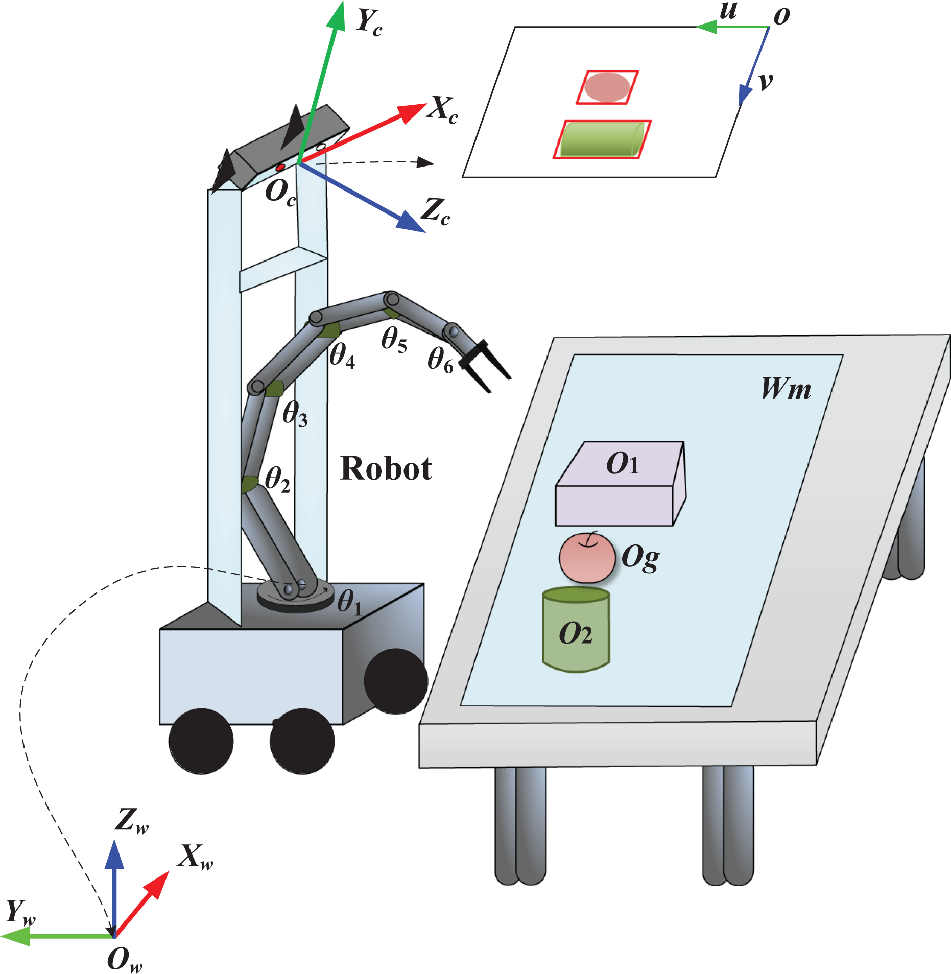
Illustration of the robot grasping the target object, where Og is the target object, O 1 is an untrained object, and O 2 refers to the detectable object. Wm describes the workspace of the manipulator.
A point p(up , vp ) in the o-uv system can be converted to cP( cxP , cyP , czP ) under OcXcYcZc according to the camera’s intrinsic matrix T = [fx , 0, uc ; 0, fy , vc ; 0, 0, 1], and its coordinate wP( wxP , wyP , wzP ) in OwXwYwZw is then obtained as follows

where
To accomplish the grasping of target object, the robot should possess the capability of object detection. In this article, SSD
11
is adopted and each detectable object is enclosed by a bounding box. In Figure 1, an apple and a cup are the detectable objects with their bounding boxes described in o-uv coordinate system. With the depth map provided by Kinect V2 camera, one can obtain the point cloud corresponding to each detectable object. In practice, the environments are complex and there inevitably exist some objects that are not trained by SSD. These untrained objects possibly disturb the grasping of detectable objects, and thus, their point cloud information is also required. The table plane where the objects are placed is firstly fitted by RANSAC,
22
and then, the straight-pass filter is applied to obtain the point clouds of the objects. And then, a 2D coordinate system OdXdYd
on the table plane is defined and it is parallel to OwXwYw
, where the projection of Od
in OwXwYw
is Ow
. To better extract the untrained objects, a prerequisite step is to remove the point clouds related to detectable objects. Then, Euclidean clustering
23
is utilized to acquire the point cloud of each untrained object. No matter detectable objects or untrained objects, with the point cloud of each object, PCA
24
shall be used to obtain the respective principal axis. Moreover, a minimum 3D bounding box
For an object Oj
, j = 1, 2,…, No
, the vertex coordinates of its 3D bounding box are calculated and then vertically projected on Wm
to form a closure region, where No
is the number of objects, Wm
refers to the manipulator’s workspace (see Figure 1) and it is a predefined zone in OdXdYd
. This closure region is bounded by a minimum envelope rectangle, which is expressed by Rs
. The four vertexes of Rs
are described as
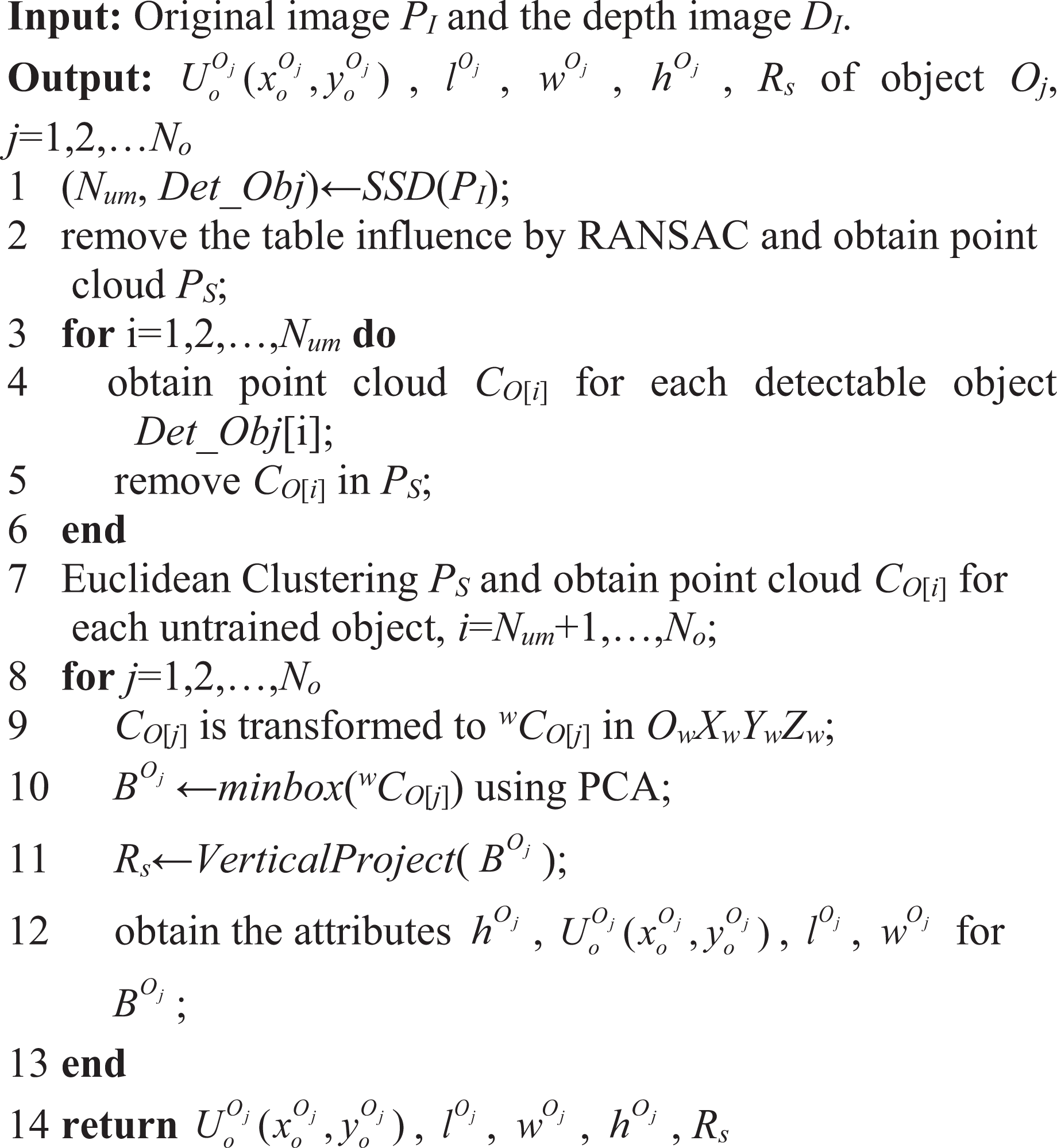
Algorithm 1 presents the information extraction process of the objects including all detectable objects and untrained objects, where Num
is the number of the detectable objects whose information is stored in Det_Obj. CO
[i] refers to the point cloud of the detectable object Det_Obj[i] for i = 1,2,…, Num
or those of the untrained objects for i = Num
+ 1,…, No
. The function minbox (
The information extraction of detectable objects and untrained objects.

Object grasping based on potential field model with elliptical cone
To achieve the grasping under disturbed scenes, the robot should move the interference objects firstly with the consideration of other objects. Artificial potential field method is a general solution to express the interaction among the objects. In reality, different objects have different shapes with respective orientation. The design of the potential field should consider the object information including its orientation and height.
Elliptical potential field
For an inclined object, the construction of the potential field is not accurate by relying on an arbitrary projected envelope rectangle, and a minimum envelope rectangle corresponding to its major axis is more preferable. Instead of adopting the rectangle-based discrete potential field, in this article, we first obtain a circumscribed ellipse for this minimum rectangle, and then, an ellipse-based continuous potential field is proposed.
As shown in Figure 2, for the minimum envelope rectangle Rs
of the object Oj
, the minimum circumscribed ellipse El
can be obtained, where F
1 and F
2 are the focal points of El
, and the points

where

The schematic minimum circumscribed ellipse El .
According to the standard ellipse equation

where
For the object Oj
, combining with

where
Substituting a and b in equations (4) into (3), the general elliptical equation of El is then acquired
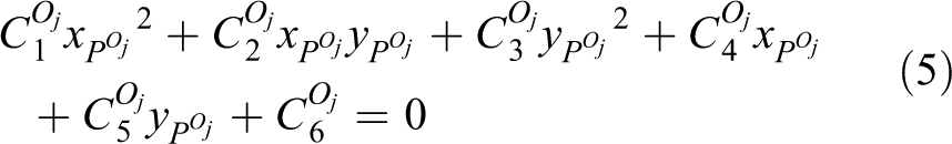
where
After the minimum circumscribed ellipse El of the object Oj is obtained, the influence of Oj can be considered by concentrically expanding El with the same eccentricity in a discrete way (see El 1 in Figure 2). However, this solution based on an incremental focal distance shall lead to a complicated calculation process. To solve this problem, a functional solution is required. Note that the potential field function is constant within the ellipse El . In the region outside El , the potential field function should conform to the following design principles:
The potential field function is continuous;
For any two positions on the plane OdXdYd , if they locate at an ellipse, whose center and eccentricity are the same as El , the influences of Oj on them are equal, which is called same-eccentricity equivalence;
The variation trends influenced by the object Oj are different for the directions of major axis and minor axis of El ;
The function is monotonically increasing if we expect that the farther a position is away from the center of El , the larger the influence of Oj is. It is referred to as attractive potential field function;
The function is monotonically decreasing if we expect that the farther a position is away from the center of El , the smaller the influence of Oj is. In this case, it corresponds to repulsive potential field function.
Calculation of the potential fields
When the manipulator cannot grasp the target object, it has to select an interference object and move it away first. The selection criterion is based on the distance to the center of the target object and smaller values represent higher priorities. The chosen interference object is called current grasped object, and other objects are subdivided into two categories: the residual interference objects and the target, and noninterference objects. The object numbers of these two categories are labeled as N r 1 and N r 2, respectively. It shall be noted that the less the current grasped object is moved, the smaller the manipulator consumes. Therefore, the influence of the current grasped object is consistent with the fourth design principle. On the contrary, every other object generates a repulsion to current grasped object, and its influence coincides with the fifth design principle.
Meanwhile, for any object Oj
with its minimum circumscribed ellipse El
, the former three items of the design principles are the basis. To satisfy these requirements, we introduce an elliptical cone
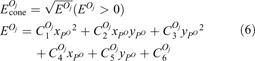
For the current grasped object Oig , its elliptical potential field function Fat should conform to the fourth design principle, and it tends to be moved along the short edge direction of projected rectangle. The attractive field of Oig is designed as follows

where dcg
refers to the distance between the object Oig
and its nearest object. μ is a given value,
Different from the object Oig
, every other object Or
generates a repulsive elliptical field

where
Considering all the objects, we calculate the resultant potential field F res as follows

where

where p represents a position in the manipulator’s workspace Wm
. If there exists more than one minimum solution, the robot shall choose the solution, which is closest to the object Oig
. Notice that the point
The flowchart of the proposed approach is shown in Figure 3. The image information and depth information of the scene are firstly provided by Kinect2. The robot recognizes the detectable objects and others are referred to untrained objects. Combining with the depth information, the point cloud of each detectable or untrained object is then obtained by Euclidean clustering. According to PCA, we acquire minimum 3D bounding box of each object including size and pose information. By comparing the Euclidean distance Dis between the target object and every nontarget object with a given threshold Dt , nontarget objects are classified into the interference objects and noninterference objects. If the number Nfer of interference objects is zero, it means that the robot may grasp the target object directly, otherwise, the robot has to move the interference objects according to the placement position solution based on elliptical cone potential fields. Note that the interference object with smaller Dis has a higher priority. Repeat the above processing until the robot seizes the target object.

The flowchart of the proposed approach.
Experiments
In the experiments, Kinect V2 is used to obtain the scene information, and a service robot with six degrees of freedom Kinova manipulator is required to grasp the target object. SSD is adopted to detect objects with 2D red bounding boxes, and then, we acquire the point clouds of untrained objects. The experiments concern the following objects: target apples, cup, beverage and box, where box and beverage belong to untrained objects.
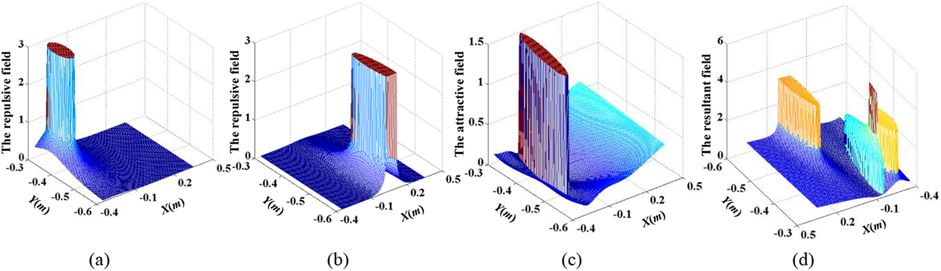
Experiment 1 considers the box and the beverage as noninterference objects. Figure 4 shows the detection result of experiment 1. Figure 5 describes the potential fields. The potential field of each object is shown in Figure 5(a) to (d), respectively, and one can obtain the resultant field, as shown in Figure 5(e). In Figure 5(b), the beverage is closed to the border of the robot workspace, and thus, the potential field seems to be cut. The video snapshots of the manipulator grasping the target apple are shown in Figure 6. It is seen that the manipulator firstly moves the cup away and places it to a new position (−0.24, −0.49) determined by equation (10), and then, the apple is grasped smoothly.
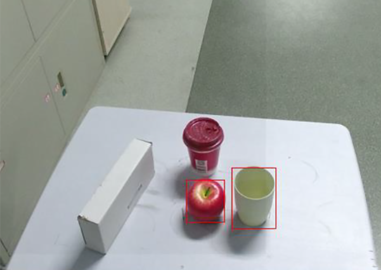
The detection result of experiment 1.

The potential fields of experiment 1: (a) The repulsive field of the apple, (b) the repulsive field of the beverage, (c) the repulsive field of the box, (d) the attractive field of the cup, and (e) the resultant field.
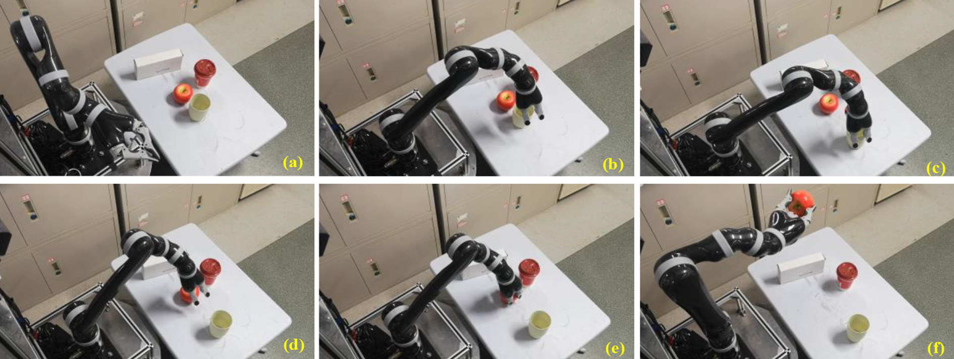
(a–f) The video snapshots of experiment 1.
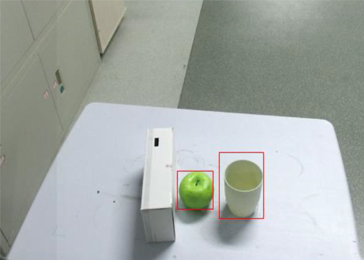
In experiment 2, the target object apple is located at the right-bottom corner of the scene. The beverage is regarded as a noninterference object and the box is seen as an interference object. Figure 7 shows the detection result of experiment 2. All the potential fields are shown in Figure 8. By combining the potential fields of all objects shown in Figure 8(a) to (c), one can obtain the resultant field, as shown in Figure 8(d). The video snapshots of the manipulator grasping are shown in Figure 9. It is seen that the manipulator firstly moves the box to a new position (−0.12, −0.46), and the apple is grasped smoothly.

The detection result of experiment 2.
The potential fields of experiment 2: (a) The repulsive field of the apple, (b) the repulsive field of the beverage, (c) the attractive field of the box, and (d) the resultant field.

(a–f) The video snapshots of experiment 2.
Experiment 3 considers two interference objects. The detection result is shown in Figure 10. Figures 11 and 12 demonstrate the potential fields and video snapshots of experiment 3, respectively. For better description of the process, it is divided into two stages: stage I and stage II. The former is to move away the interference cup, and in the latter, the interference box is moved. The potential fields of the box, apple, and cup in stage I are shown in Figure 11(a) to (c), and at this moment, the current grasped object cup corresponds to the attractive one. Based on the best placement result obtained by the resultant field shown in Figure 11(d), the cup is moved to its new placement position and the moving process is shown in Figure 12(a) to (d). After the cup is released, the robot continues to execute stage II. In this stage, the box becomes the current grasped object, and thus, it generates an attractive field, whereas the cup corresponds to a repulsive one. Note that for the target apple, it always generates the repulsive field. Combining the fields shown in Figure 11(b), (e), and (f), one can obtain the resultant field (see Figure 11(g)). On this basis, the robot grasps the box and moves it to its new placement position, and the moving process is shown in Figure 12(e) to (g). Finally, the apple is grasped, as shown in Figure 12(h) to (i).
The detection result of experiment 3.

The potential fields of experiment 3 with two-stage interference objects moving. Stages I and II correspond to panels (a)–(d) and (e)–(g), respectively. (a) The repulsive field of the box, (b) the repulsive field of the apple, (c) the attractive field of the cup, (d) the resultant field of stage I, (e) the repulsive field of the cup, (f) the attractive field of the box, and (g) the resultant field of stage II.

(a–i) The video snapshots of experiment 3.
Conclusion
In this article, a robotic grasping approach with elliptical cone-based potential field is proposed to handle the challenge from disturbed scenes. Based on the extraction results of SSD and Euclidean cluster for the detectable and untrained objects, the robot acquires the attractive or repulsive potential field of each object and determines the placements of interference objects. Compared to conventional circumscribed circle envelope, the circumscribed ellipse envelope in this article is better due to its small occupation space among the continuous closed convex curves. The form of ellipse can reflect the poses of different objects with better fitting degrees. The resultant continuous elliptical cone fields can improve the placement position of interference object. The experimental results verify the effectiveness of the proposed approach. In the near future, we shall conduct more deep research on the moving sequence of interference objects as well as the grasping in a larger environment that also relies on the navigation ability of the robot.
Footnotes
Declaration of conflicting interests
The author(s) declared no potential conflicts of interest with respect to the research, authorship, and/or publication of this article.
Funding
The author(s) disclosed receipt of the following financial support for the research, authorship, and/or publication of this article: This work was supported in part by the National Natural Science Foundation of China under grant nos 62073322, 61633020, 61633017, 61836015, and in part by the Open Foundation of the State Key Laboratory of Management and Control for Complex Systems, Institute of Automation, Chinese Academy of Sciences under grant no. 20190106.