
Abstract
This article treats the design and implementation of a multi-input multi-output fractional-order controller for a nonlinear system composed of a tendon-driven continuum mechanism. As the continuum can be deformed along all Cartesian directions, it is suitable for the application as a flexible neck of a humanoid robot. In this work, a model-based control approach is proposed to control the position of the head, that is, the rigid body attached to the top of the continuum mechanism. Herein, the system is modeled as a rigid body on top of a nonlinear Cartesian spring, with an experimentally obtained deflection characteristic which provides a simple and real-time capable model. By nonlinear feedback, the output dynamics are linearized and decoupled, which enables the design of single-input single-output fractional-order controllers for the regulation of each output independently. The design of a fractional-order
Keywords
Introduction
Continuum mechanisms provide a passive compliance as the continuum structure reacts to any kind of disturbance with a deformation. The mechanism can therefore collide with the environment without being damaged, which is termed “mechanical robustness.” Mechanisms of this kind are used as finger joints in robotic 1 or prosthetic 2 hands, quadrupedal spines, 3 humanoid necks or spines, 4 or whole robotic arms made of serially attached mechanisms. 5 Furthermore, parallel continuum robots possess a similar design, with multiple continua in between two rigid platforms. 6
Besides, the use of continuum mechanisms favors an underactuated robotic design. Underactuated robotics is an emerging research direction in the field of robotics and has the advantages of lightweight, low energy consumption, excellent performance, and broad development prospects. 7
In this work, a tendon-driven mechanism is considered with a continuum structure in between rigid platforms, whereas the system is currently used as a robotic neck of DLR’s humanoid robot DAVID (Figure 1).

Tendon-driven continuum mechanism applied as a neck in DAVID. 4
To make use of this mechanism as a component in a robot, a coordinated motion is desired. For example, during manipulation tasks or locomotion, DAVID shall perceive his environment, which requires to control the pose of the head. As the continuum structure will deform from any kind of externally applied wrench, a model-based controller is beneficial. However, rigorous models that incorporate all deformations are computationally expensive and impose a limitation on a real-time control loop.
Most recently, Chikhaoui and Burgner-Kahrs 8 outlined that “Paradoxically, while challenges regarding control of soft continuum robots were identified in the literature…, few research is clearly focused on control.” Control approaches in literature for continuum mechanisms can be classified into kinematic, static, or dynamic controllers. The majority are kinematic controllers which utilize a Jacobian to relate desired task space positions to desired actuator positions. A feedback controller is closed locally in each actuator which simplifies the implementation and reduces the effect of model inaccuracies. Model-based Jacobian based on kinematic models, 9 static models, 10 or data-driven approaches 11 are proposed. Quasistatic control approaches are presented by Bosman et al. 12 based on a volumetric finite element model and by Melingui et al. 13 based on a trained neural network and an adaptive controller. The first dynamic control approach is presented by Gravagne et al. 14 A single-input single-output (SISO) set point vibration damping controller is formulated in the configuration space, and asymptotic stability can be shown for the linearized system. An SISO configuration space impedance controller is presented by Toscano et al. 15 for a single section of the pneumatically driven bionic handling assistant. For multiple sections, Falkenhahn et al. 16 present and experimentally verifies model-based dynamic controller in the actuator space with a cascaded control architecture. The outer multi-input multi-output (MIMO) controller uses a feedback linearization to cancel the known dynamics of the model. The inner controller then ensures that the desired pressures from the outer loop are tracked accurately. A dynamic controller without model knowledge is presented by Braganza et al., 17 who apply a continuous asymptotic tracking control strategy for uncertain nonlinear systems with proved asymptotic tracking and without any model of their pneumatically driven Octarm.
To the authors knowledge, underactuation of continuum mechanisms is not treated in the dynamic controllers explicitly, whereas the kinematic and quasistatic controllers neglect dynamic effects from the continuum, end effector inertia, or the stiffness of the mechanism. Furthermore, disturbances such as unmodeled friction or external contacts cannot be addressed by kinematic and static controllers.
The model-based approach developed in this work is a dynamic controller in the task space of the continuum mechanism. The underactuation is specifically treated by a transformation to the input–output normal form, that is, linearizing and decoupling the input–output dynamics, and enables control strategies from linear control theory. In practice, the linearization and decoupling however is jeopardized by, for example, model parameter mismatches. Therefore, this work proposes to model and identify second-order linear transfer functions for the remaining output dynamics and apply an extensively robust control approach to handle the remaining coupling and nonlinearities. In this respect, the concept of fractional-order (FO) control is investigated, which extends a general linear proportional derivative (PD) controller with an additional coefficient to account for robustness and a fast transient similarly, as assessed by Deutschmann et al. 18
Since relevant works by pioneers such asOustaloup, 19 Oustaloup et al., 20 and Podlubny, 21 FO calculus has attracted research community as well as industrial community and its application in science and engineering is increasing, 22 –24 Regarding control systems, it is observed that FO controllers perform better than their corresponding integer-order controllers. 22,23,25 Another advantage is that the FO controller provides more number of tuning parameters, making it possible to incorporate additional design specifications in the controller design. 22,26
The main contribution of this work is to extend the FO controller presented by Deutschmann et al. 18 to the MIMO case by the transformation suggested by Deutschmann et al. 27 The controller proposed here is a generalized FO Proportional Derivative (FOPD) controller since, as will be demonstrated, it provides a good balance between dealing with more demanding control requirements and keeping simplicity and easy-to-tune capabilities. Our approach is examined and validated in three experiments on the real robotic neck in Figure 1.
Problem statement and modeling
A tendon-driven continuum mechanism can be used in a variety of applications that usually involve a coordinated deformation of the continuum to move the upper platform spatially. To induce this deformation of the continuum, a controller is needed. The main objective in this connection is to control the pose of the upper platform that is attached to the end of the continuum mechanism which can be described by the generalized coordinates
Rigorous mechanical models of continuum mechanisms involve nonlinear partial differential equations, 28 which result in a large number of degrees of freedom and yield that these approaches are not suitable for real-time control. 29 As outlined earlier, this work relies on a reduced nonlinear model which is based on the following assumptions.
Assumption 1
A rigid body, the head, is attached to the upper platform of the mechanism with known mass
Assumption 2
The deformation of the continuum can be modeled according to Deutschmann et al., 30 that is, resembles a nonlinear Cartesian spring system based on multivariate polynomials.
Assumption 3
The tendons are inelastic.
Assumption 4
The dynamics of the tendon tension control loop is sufficiently fast, that is, a commanded desired tendon tension is instantaneously realized by the actuation system.
Assumption 5
The state of the system
The generalized coordinates


with the following quantities: The symmetric, positive definite mass matrix The Coriolis and centrifugal matrix The vector of generalized gravitational forces The vector of generalized damping forces of the continuum The tendon coupling matrix The vector of the generalized forces resulting from a deformed continuum
Tendon tension forces

with
The unitary tendon direction vector


Schematic drawing of the tendon-driven continuum mechanism.
Input–output normal form
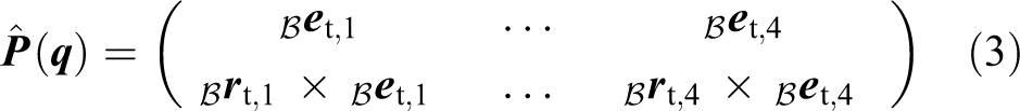
The control approach of the present article will apply the concept of FO control, which is linear and only SISO, on an MIMO system. The nonlinear part of the controller first makes use of the input–output normal form to linearize and decouple the output dynamics. Due to the underactuation, a total number of four outputs, denoted

where

With equation (6), the dynamics of

By inserting equation (7) into equation (1) and rearranging, the output dynamics follows

with


In general, the choice of outputs is a largely discussed topic as certain, favorable properties can be imposed to the input–output dynamics, cf. Isidori.
33
In the present case, the choice is motivated by the fact that the coordinates y and z are strongly coupled toward the angular motions of
Under the condition that the matrix

and

Equations (13) and (7) together are the so-called “Input–output normal form.” In the following section, the new control input
The nonlinear feedback controller (12) is only applicable if the dynamics for the remaining coordinates (7) are stable. To analyze the stability in this work, the concept of zero dynamics is applied.
33
For the constraint that the output is constant, for example,

A global stability proof of equation (14) is complex and is not treated herein. In contrast, local asymptotic stability of equation (14) is investigated using Lyapunov’s indirect method. The eigenvalues of the linearized zero dynamics (The internal dynamics are linearized at the static equilibrium
Controller design
This section treats the controller design for the linearized and decoupled output dynamics (13). By observing the real hardware, the output dynamics cannot be fully decoupled and linearized due to model parameter mismatches, unmodeled effects like tendon friction or inaccuracies in the real-time pose estimation. Therefore, the input–output characteristic is measured for each of the four outputs experimentally and approximated by second-order transfer functions for each input–output pair. The four experimentally found transfer functions
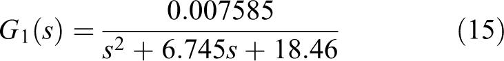


where inputs ui are tendon tensions and outputs yi are axial position for tendon i=1 and angular positions for tendons i=2,3,4.
For the control of these dynamics an FO controller is proposed, more specifically an FOPD controller of the form

with kp being the proportional gain, kd the derivative gain, and α the FO of the derivative.
Fractional order proportional integral derivate (FOPID) controllers benefit from the generalization of the orders of the derivative and integral parts and introduce these two orders in the controller structure, increasing the number of controller parameters to tune and allowing the fulfillment of more control specifications. 34 –37
In our case, the FOPD controller has three parameters to tune, that is, kp , kd , and α, and therefore three control specifications can be addressed. For the selection of these specifications we rely on the control approach previously proposed by Monje et al., 23 where the control specifications to be met are
phase margin ϕm and gain crossover frequency ωc,
robustness to gain changes around the nominal crossover frequency ωc, and
robustness to disturbances.
The equations relating the phase margin ϕm and gain crossover frequency ωc are


where
In order to achieve control robustness to gain changes, the open-loop flat phase specification is another common constraint in controller design, as demonstrated in the studies by Monje et al. 23,26 and Chen et al. 37 This specification is formulated as follows

If equation (22) is fulfilled, then the phase of the open-loop system represented in its Bode diagram is flat around the crossover frequency. This implies that variations of the gain around its nominal value will not cause a significant change of the phase margin and then the overshoot of the response will keep constant. In our system, the model gain is affected by the payloads of the device, as firstly proved in the study of Deutschmann et al. 18 Several experiments have been conducted on the neck platform with different masses at the top and after system identification, the models show a significant variation of the gain in comparison with other model parameters, whose variations can be neglected. Therefore, the flat phase property of the open loop will guarantee robustness of the system to gain/payload changes.
Taking all this into account, our control approach will be based on solving equations (20) to (22) for the FOPD controller in equation (19). This set of three equations with three unknown parameters kp , kd , and α is solved using MATLAB function FMINCON, 38 which finds the constrained minimum of a function of several variables.
For our case study, the phase margin and crossover frequency are set to


Since the results obtained are rather similar for the four tendons, we will focus on the data referring to tendon
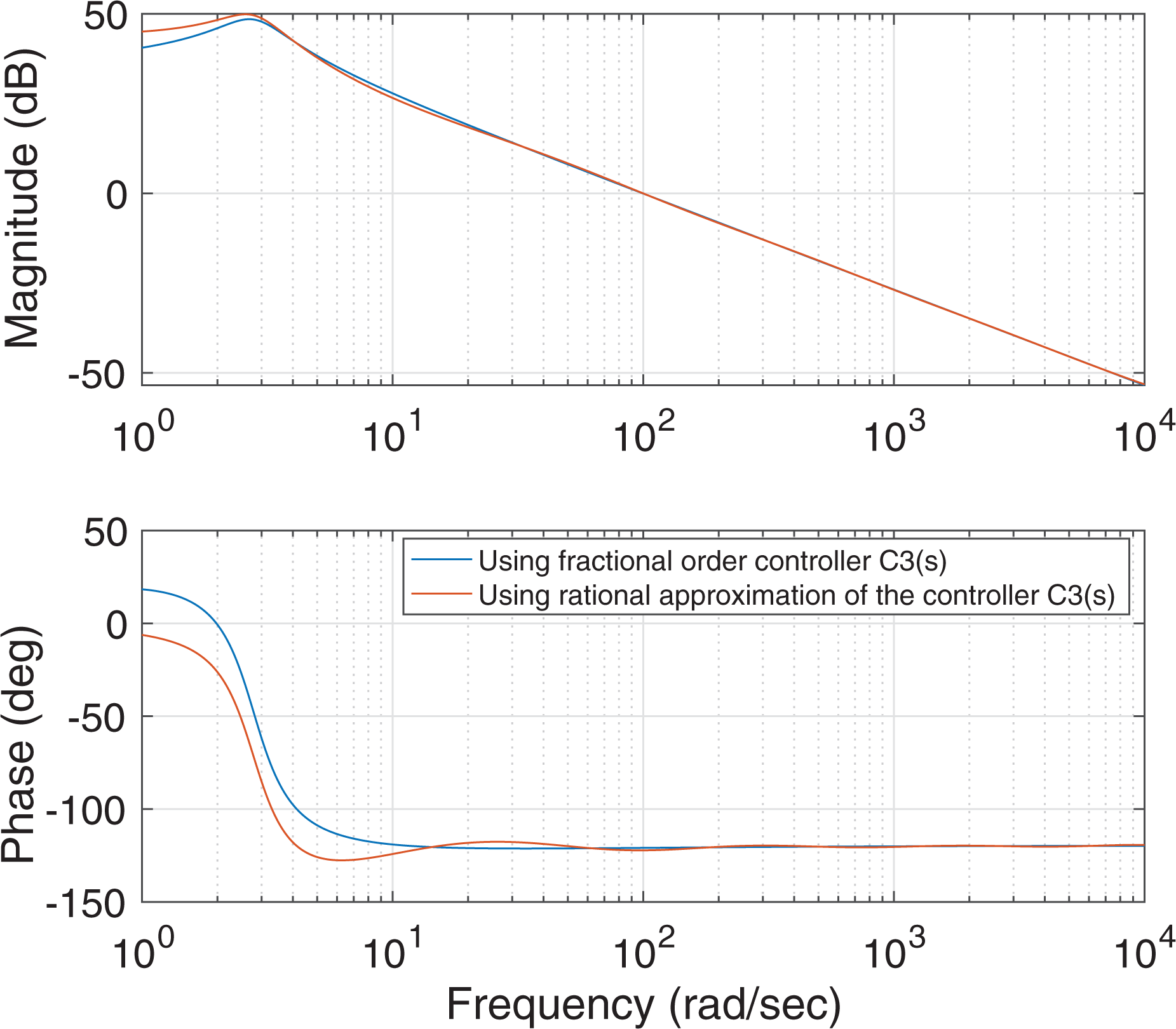
Bode diagram of the open-loop system
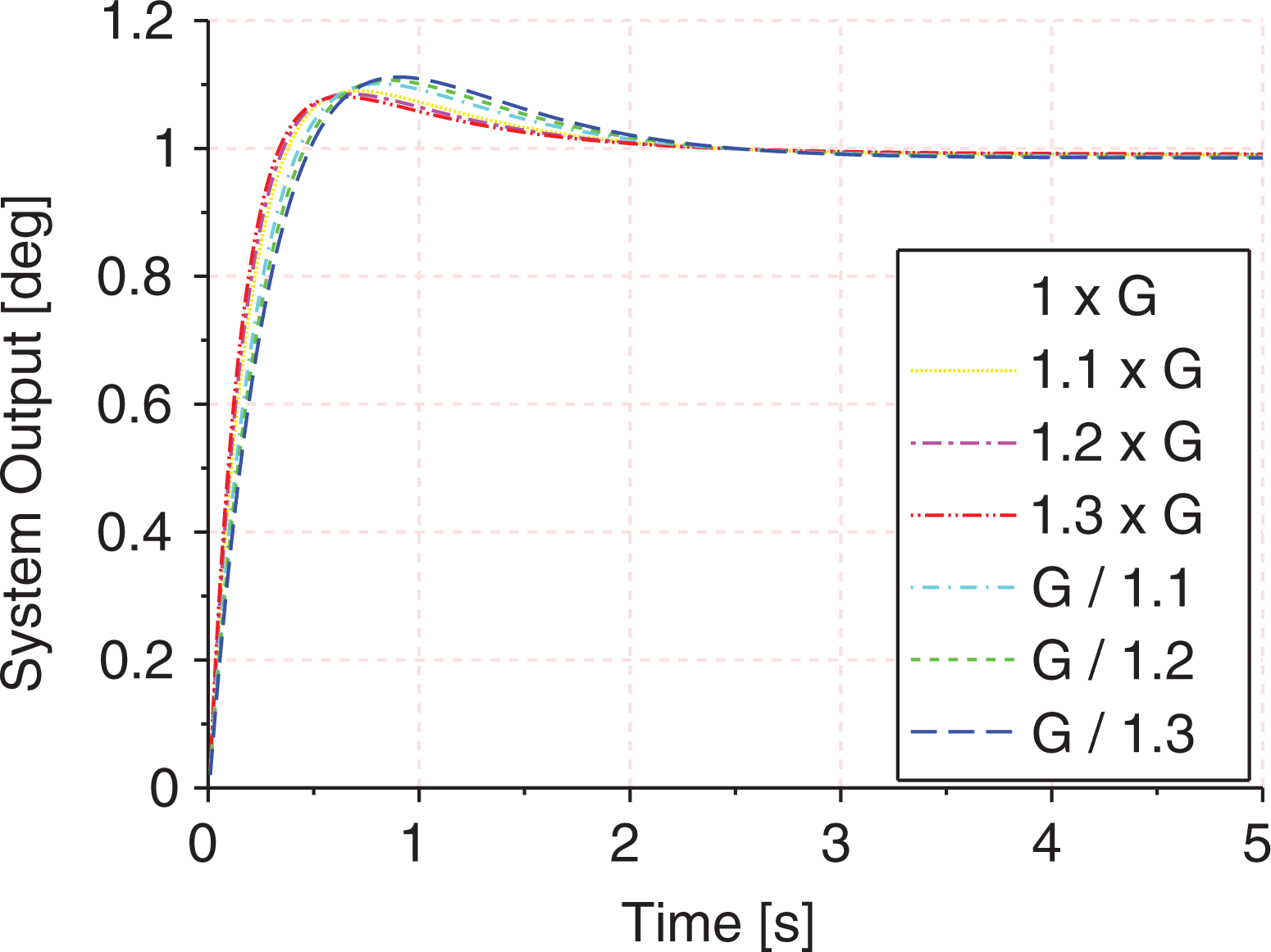
Step responses of the closed-loop system with plant G
3 and controller
Regarding the implementation of FO controllers, FO transfer functions are usually approximated by integer-order ones with a very similar dynamics, but much easier to handle. There are a considerable number of methods to find such approximations and a comparison among them is difficult to address, because even though some of them are better than others in regard to certain characteristics, the relative merits of each approximation depend on the differentiation order, on whether one is more accurate to fit a frequency behavior in a particular frequency range of interest or to fit the response in the time domain, or on how large the admissible transfer functions may be, among others. A good review of these approximations can be found in the study of Monje et al. 26
In our particular case, to implement the FO controllers in the real setup, the transfer functions in equations (23) to (26) have been approximated to those of an integer-order controller using the frequency identification method performed by MATLAB function invfreqs. A continuous integer-order transfer function is obtained which fits the frequency response of the FO controller in a frequency of two decades around the gain crossover frequency, with four poles and four zeros. Later this transfer function is implemented as a transfer function block in the MATLAB control setup in charge of running the experimental tests with the real robotic platform.
This method has been chosen due to its accuracy in the frequency range of interest, but any other of the techniques in the study of Monje et al. 26 could also be suitable for this purpose.
Experiments
This section will treat an experimental investigation of the developed control system. The steady-state accuracy, the transient behavior, and the robustness against external disturbances of the implemented controller are evaluated in three experiments which are reported in three corresponding sections respectively. Beforehand, the setup of the experiments is presented.
Experimental setup
The neck of the humanoid robot DAVID of the DLR, see Figure 1, serves as experimental platform. Thus, the rigid body of the system is the head of the humanoid, and its mass and inertia result from the design of the head, that is, the arrangement and the selection of the housings, the camera and other sensors, as well as the tendon hinges. The lower platform and the top platform are manufactured from aluminum to ensure an accurate placement of the head with respect to the rest of the humanoid robot. The continuum is modeled from silicon
39
and the surface in between silicon and aluminum is designed to ensure a firm interconnection. The geometrical shape of the continuum is cylindrical, with a radius of
Tendon force controller and pose measurement
A tendon tension controller is implemented in each actuator locally to ensure that the tendons will not go slack during motion. By feedback of the measured tendon tension forces

The control law (27) incorporates a feedforward term, a feedback term, a compensation of the dry frictional effects
For state estimation, the concept proposed by Deutschmann et al. 42 is used, which performs a nonlinear least square minimization of a pose dependent error function. For the corresponding velocities, the numerical derivative of the estimated pose is computed as the solution of the optimization problem and generates smooth pose estimates.
Set point trajectory generation
As mentioned earlier, the generalized coordinates are coupled during a motion. To command feasible desired set points for the output
The solutions of the static equilibrium equations for some desired tendon forces

are computed using an iterative approach and the desired outputs
Steady-state accuracy
The steady-state accuracy describes the remaining error between the outputs
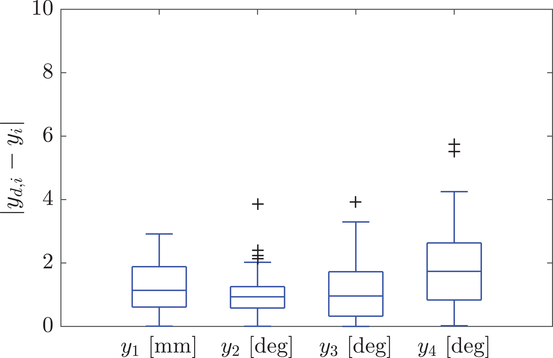
Boxplot to express the steady-state error of the four output components in
Transient behavior
The transient behavior of the closed loop is investigated by a motion sequence where the spatial testbed is driven to 10 consecutively reached set points. The transition time in between the desired set points is set to 1 s, which generates a dynamic motion. The recorded poses, belonging to this motion sequence, are depicted in the top row of Figure 6 and include typical motions of the robotic neck. The corresponding data of the hardware to assess the transient behavior are illustrated in Figure 6. Again, the componentwise output error

Transient behavior of the MIMO FOC controller that drives the system to a sequence of consecutive set points. The gray areas mark the periods at which the desired output has reached its set point. Top plot: componentwise output error
The transient behavior of the nonlinear controller is stable for the investigated trajectory, and the controller manages to move the system along the 10 desired set points with a transition time of 1 s. However, for set points 1, 3, and 9 the controller does not manage to stabilize the system to the desired set point in this short time period, which can be observed by a nonsteady control error. The highest control error is present in y
4, which coincides with the behavior previously discussed in the steady-state part of the Experiments section. By looking at the desired tendon tension forces, two important observations need to be noted. The controller demands high tension forces in the tendons in the transient of the motion, considering a maximum tolerable tension of 80 N. In case the inertia or Coriolis terms are not generated with accurate parameters, the nonlinear feedback might overcompensate these, which would result in such high tension forces during the transient. The second observation reveals that the partial feedback linearization controller desires negative tendon tension forces, which is not feasible as these cannot be realized by the tendons. As introduced earlier, a pretension
External disturbances
The robustness of the controller is examined in the following experiment and Figure 7 depicts the response of the system. Starting from the initial pose, the mechanism is driven to a desired set point

Investigation of the behavior of the closed loop while an external disturbance is applied on the system. The red areas mark the time periods where the external (manual) disturbance is applied.
Conclusions
This article has dealt with the design and implementation of an MIMO FO controller for a nonlinear system composed of a continuum mechanism currently used as a neck of a humanoid robot.
A reduced nonlinear model of the system consisting of the rigid body dynamics and an experimentally obtained approximation of the nonlinear Cartesian spring characteristics of the continuum with multivariate polynomials is used for the position control approach. By nonlinear feedback, the output dynamics are linearized and decoupled, which enables the design of SISO FO controllers for the regulation of each output independently. In theory, a transfer function with a double integrator would imply that only damping is needed to generate a flat phase for robustness. 18 However, based on observations, the output dynamics cannot be fully decoupled and linearized due to, for example, model parameter mismatches. Therefore, the input–output characteristic is identified experimentally for each output and approximated by second-order transfer functions. To emphasize the applicability, an FOPD control is tuned by specifying a flat phase (22), phase margin (20), and crossover frequency (21).
Three different experimental tests have been carried out for the study of the steady state, transient behavior, and robustness of the closed-loop system to external disturbances, respectively. The results conclude that the control system shows a rather robust behavior, enhancing the performance of the soft link when it comes to trajectory tracking and model uncertainty.
As also discussed in the Experiments section, the partial feedback linearization controller demands negative tendon tension forces, which is not feasible as these cannot be realized by the tendons. As a preliminary solution, saturation has been implemented in the control loop in order to avoid commanding negative tensions. Future research will focus on this control problem.
Footnotes
Declaration of conflicting interests
The author(s) declared no potential conflicts of interest with respect to the research, authorship, and/or publication of this article.
Funding
The author(s) disclosed receipt of the following financial support for the research, authorship, and/or publication of this article: This research was supported by the HUMASOFT project, with reference DPI2016-75330-P, funded by the Spanish Ministry of Economy and Competitiveness, and from the RoboCity2030-DIH-CM Madrid Robotics Digital Innovation Hub (Robótica aplicada a la mejora de la calidad de vida de los ciudadanos, Fase IV; S2018/NMT-4331), funded by Programas de Actividades I+D en la Comunidad de Madrid and cofunded by Structural Funds of the EU.