
Abstract
In the installation process of large-scale external cladding, the labor intensity is high, and it is dangerous and hard to guarantee good construction quality. In view of these issues, this study designs a construction robot for external cladding installation, as a better solution. First, the advantages and disadvantages of the current building external cladding hanging process are discussed. The components, suitable for automatic installation, are selected to develop an automatic installation process for the building external cladding. According to the process steps and installation action flow, the installation robot is first adjusted. After the design of a step-by-step workflow of positioning and installation, a robot with a six-degree-of-freedom string-mixing mechanism is designed. Finally, a prototype of the proposed external cladding installation robot is developed, and the system is experimentally verified under simulation conditions and real operation. The test results show that the external cladding installation robot system has a strong theoretical basis. The series-parallel hybrid six-degree-of-freedom structure is reasonable, design wise. It helps to complete the automatic installation of the building external cladding and improve the automation level of large-scale plate installations.
Introduction
The construction robot industry has developed rapidly over the past 30 years. It covers applications such as painting, welding, large container assembly, concrete prefabricated slab production lines, exterior wall finishes and inspections, floor calendering, and cleaning. At present, specialized research institutions have been thriving in Japan, the United States, Germany, the United Kingdom, South Korea, Spain, China, and other countries in the world, helping in research and development of automated building construction equipment.
The construction robot first appeared in Japan. The steel beam fireproof layer spraying SSR series robot, developed by Qingshui Company, is recognized as the world’s first construction robot to be put into operation. 1 Kashima Construction Co., Ltd has developed an auxiliary plate mounting robot, named Mighty Hand, which has a weight of 720 kg and a maximum payload of 350 kg. It is mainly used for the installation of concrete, glass, stone, and other building boards. 2 In the United States, a robot for bricklaying, called “Sam,” has been developed. It includes a conveyor belt, a robotic arm, and a concrete pump. 3 The Fraunhofer Institute for Manufacturing Engineering and Automation IPA (FhG IPA Stuttgart) has developed a fully automatic tiling robot system, using the GMF Robotics S-420F as the body of the system, with six degrees of freedom in the effective working space. The end effector of the inner robot can adjust its position and attitude. 4 GRR UK has developed a Geko250 device for wall and ceiling installations. The device is small in size, strong in carrying capacity, and has three degrees of freedom. It can be installed with a large external cladding of 250 kg. It is suitable for working in small spaces. 5 The glass siding installation robot, developed in Korea, adopts a series-parallel hybrid structure, with the characteristics of a large moving space, high payload, and high motion precision. 6 The Spanish Institute of Industrial Automation has developed an auxiliary device for installing wall plasterboard, based on human–machine cooperation. This device can assist workers to quickly install a 3000 × 500 × 90 mm3 gypsum board, which weighs 70 kg, greatly improving manual efficiency. 7 The Israel Institute of Technology has successfully developed a floor-mounting robot that uses a two-dimensional vision system, to position the floor tiles to be installed. All operations are performed by the robot, including positioning, calibration, and installation. 8 In China, research on construction robots began in the early part of this century, focusing on high-rise building cleaning, painting robots, and some construction machinery automation, but the research work is still in its infancy. 9 –12 Among them, Harbin Institute of Technology has developed a remotely controlled wall crawling inspection robot. It can be used for wall inspection and spraying of buildings or large storage tanks. Shenyang Institute of Automation of Chinese Academy of Sciences develops underwater operation robots and excavation robots. Shandong University of Science and Technology and other units have created a coal mine underground shotcrete robot.
In summary, in the field of large-scale external cladding installation, domestic and foreign research is still at early stages. Generally, the known studies are about the modification of existing construction machinery and are mostly limited to indoor operations. The installation height is also limited by the original construction machinery capabilities. The installation device is not able to fully reach its potential. At the same time, for the installation of high-rise building external claddings, the required panels are first transported to the designated floor and then installed indoors manually or using some equipment. So, the outer surface of the external cladding cannot be visually observed. Therefore, the robotization of the installation of the building external cladding and the operability of the installation work are yet to be realized and optimized, as they are still the major problems for the installation of the external cladding.
This article is under the support of the National High-Tech Research and Development Program. The key technologies of the external cladding installation robot system are studied, according to the installation process of the building board and the environmental conditions of the installation site. The aim is to develop an automated and intelligent construction device, suitable for the installation of the building external cladding. The development process of the external cladding installation robot system is presented as follows.
External cladding installation process analysis
The installation method for the external cladding has different installation processes, according to different factors such as material, function, and design. After more than 20 years of development, relatively mature construction methods and related national standards and industry standards have been formulated. 13 According to the installation and fixing method, external cladding installation is about fixing the external cladding panel or component to the external cladding support system. Therefore, before determining the construction process and the overall design of the robot, the main external cladding installation methods should be described and studied. A variety of installation and fixing methods are employed, depending on different wall types: stone external cladding, glass external cladding, metal external cladding, and so on.
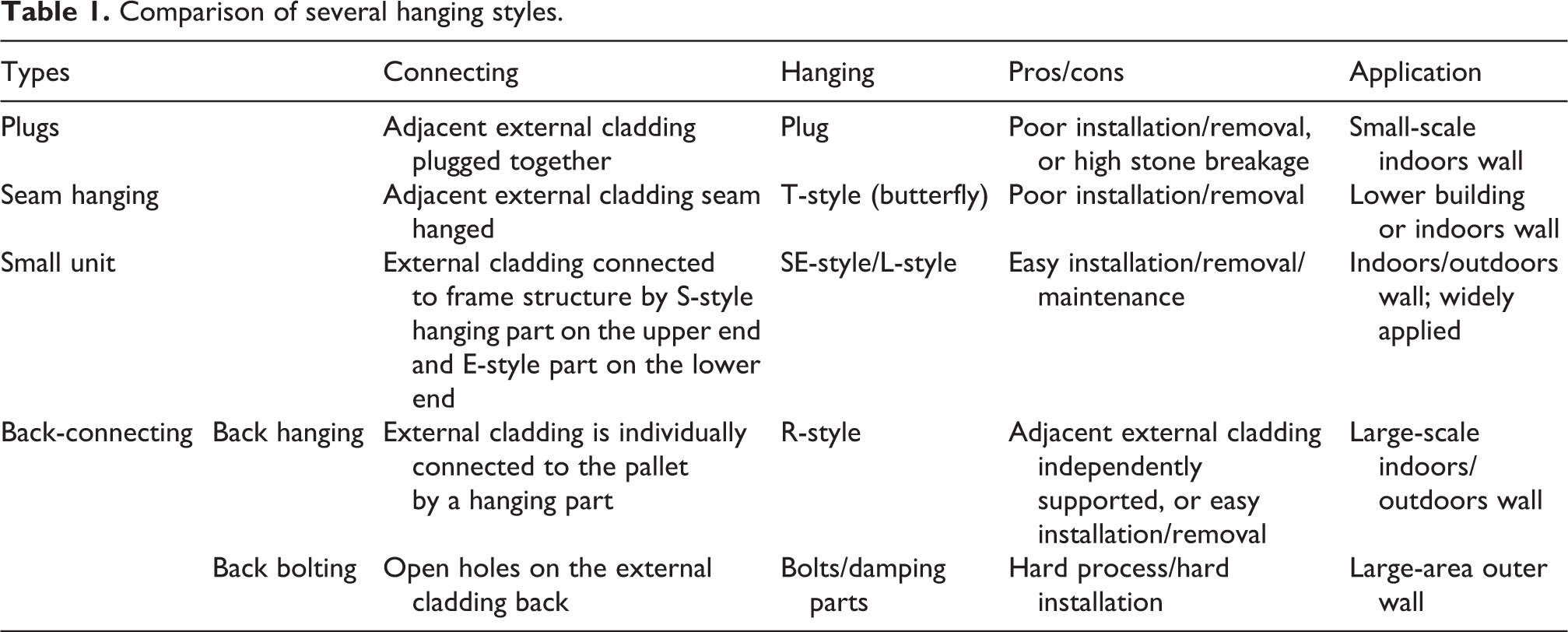
In the mid-1980s, the dry hanging installation process of stone external cladding was introduced. After 30 years of application, development, and innovation, a dry hanging technology and construction method have been established. In Table 1, the advantages and disadvantages of common pendant forms and processes are compared. Figure 1 shows the schematic diagrams of various types of pendant mounting nodes. 14 –16
Comparison of several hanging styles.

Schematic diagrams of the connection between a typical pendant and a wall: (a) fork pin dry hanging method, (b) seam hanging dry hanging method (T-shaped pendant), (c) small unit dry hanging method (SE-type pendant), (d) back hanging type (R-type pendant), (e) back bolt type, and (f) back card type hanging method.
Among the commonly used hanging parts mentioned above, the T-shaped hanging parts appeared first. They are characterized by low cost, simple process flow, and easy implementation of technology. Therefore, these parts have been widely recognized by the industry. They are also a commonly used type in stone dry hanging, where side slotting is used. The T-shaped pendant connects the plate to the frame structure, as shown in Figure 1(b). Since each pendant connects two pieces of stone, each row of stone panels, on the entire external cladding, is joined together from top to bottom, resulting in stress accumulation. Especially at the contact area, between the pendant and the plate, the stress is the highest, but the thickness of the plate is the lowest. Therefore, cracking may appear. After installation, it is impossible to replace any stone panel separately, making the maintenance work very difficult. Therefore, the stone installation method with T-shaped pendant is gradually abandoned, while more specifically, the T-shaped pendant has been banned for the decoration of high-rise exterior wall.
Due to their unique structure, SE-type pendants and R-type pendants can be easily disassembled, through the gap between adjacent external claddings, after installation, which brings great convenience to the maintenance and replacement of the external cladding. Therefore, the installation types of SE-type pendants, R-type pendants, and so on are widely used. In addition, when mounting, using SE-type pendants or R-type pendants, it is only necessary to complete on-site mounting, which suits better for a robotic automated installation. Taking into account the above factors, the SE and R type are selected for this research.
Automated external cladding process development
Through the analysis of the installation process of SE- and R-type pendants, the optimal installation action flow of SE combination pendant and R-type pendant is developed, as shown in Figure 2.

Installation process comparison: (a) SE-type pendant installation process and (b) R-type pendant installation process.
According to the installation process of the SE type and the R type, the process flow of the automated external cladding installation is shown in Figure 3. During the installation of the external cladding by the robot system, it is necessary to ensure that the external cladding is parallel to the main frame structure (wall surface) and that the upper and lower edges are parallel to the secondary frame structure. In this way, the pendant can be hung into the recess of the main pallet. At the same time, in order to realize the automatic installation of the external cladding, it is necessary to ensure the accuracy of the posture of the external cladding. Then, the position of the external cladding is adjusted, to complete the installation and positioning.
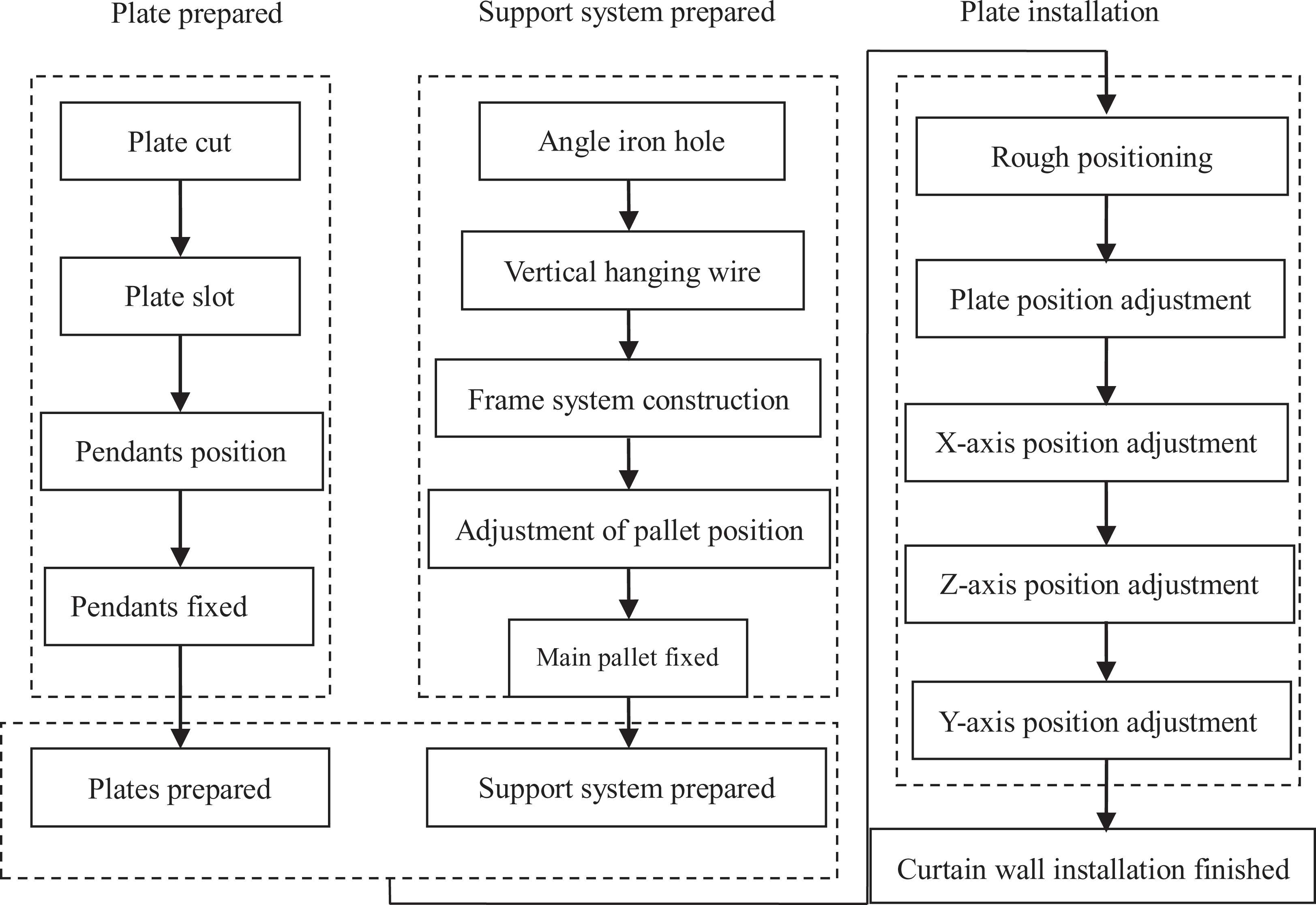
Process flow for automated external cladding installation.
Robot design of external cladding installation
Through the above analysis of the dry hanging process and the development of the automated external cladding installation process, the workflow of the installation robot is divided into two steps of attitude and position adjustment. The posture adjustment is performed first, followed by the position adjustment (Figure 4). To achieve the above workflow of installation, the robot requires six degrees of freedom.
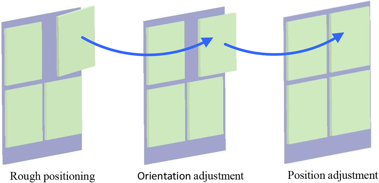
External cladding posture adjustment.
Traditional six-degree-of-freedom series-structure manipulator is used, to realize the installation and positioning of the external cladding (the mechanism diagram is shown in Figure 5). The adjustment process is as follows: First, three joints rotating around the X, Y, and Z axes are used to realize the end posture adjustment of the manipulator. In other words, the first three rotating joints (joints 1, 2, and 3) are adjusted, to make sure that the external cladding is installed parallel to the installation wall and that the upper and lower edges of the external cladding are installed parallel to the horizontal edge of the external cladding, which is already installed. The three moving joints (moving pairs X, Y, and Z) realize the adjustment of the end effector position of the mounting robot. The external cladding is also moved to the installation position, to complete the final positioning installation by the robot. In this article, the six-degree-of-freedom installation manipulator is divided into a three-degree-of-freedom position adjustment mechanism and a three-degree-of-freedom posture adjustment mechanism, conforming with the installation process of the external cladding and simplifying the installation of the manipulator mechanical and control system.

Serial robot mechanism diagram.
Although the installation manipulator with a series structure has a simple setup and a large working space, it has insufficient stability and load capacity for this occasion. Therefore, the series structure is not suitable for an external cladding installation robot system. Compared to the series structure, the parallel structure has good stability and bearing capacity, while it can reduce the weight of the installation robot itself and increase the energy-to-weight ratio. These are beneficial to the high-altitude operation of the robot. In addition, the movable platform of the parallel structure can be designed as a platform with a larger area, providing sufficient space for manual operation. The working space of the parallel mechanism is small relative to the series mechanism, but, considering the rough positioning of the moving body and the inclination of the ground, the posture-angle change of the mounting manipulator is also small. Therefore, the system uses a parallel platform, instead of the three rotating joints, in Figure 5, to realize the end posture adjustment of the robot.
Through the structural design, the system adopts the 3UPS/S parallel structure, to realize the posture adjustment of the robot, while it adopts the parallelogram structure, to realize the three-degree-of-freedom motion. This can improve the overall bearing capacity and stability of the robot. At the same time, the Z-direction coupled motion, generated by the parallelogram structure, can compensate for the Z-direction motion by interpolation. Based on the above design and research of the robot structure, a six-degree-of-freedom series-parallel hybrid installation robot system is proposed. The structure diagram is shown in Figure 6. The series-parallel hybrid structure offers the respective advantages of the large working space of the series mechanism and the strong bearing capacity of the parallel mechanism, meeting the process and performance requirements of building external cladding installation.
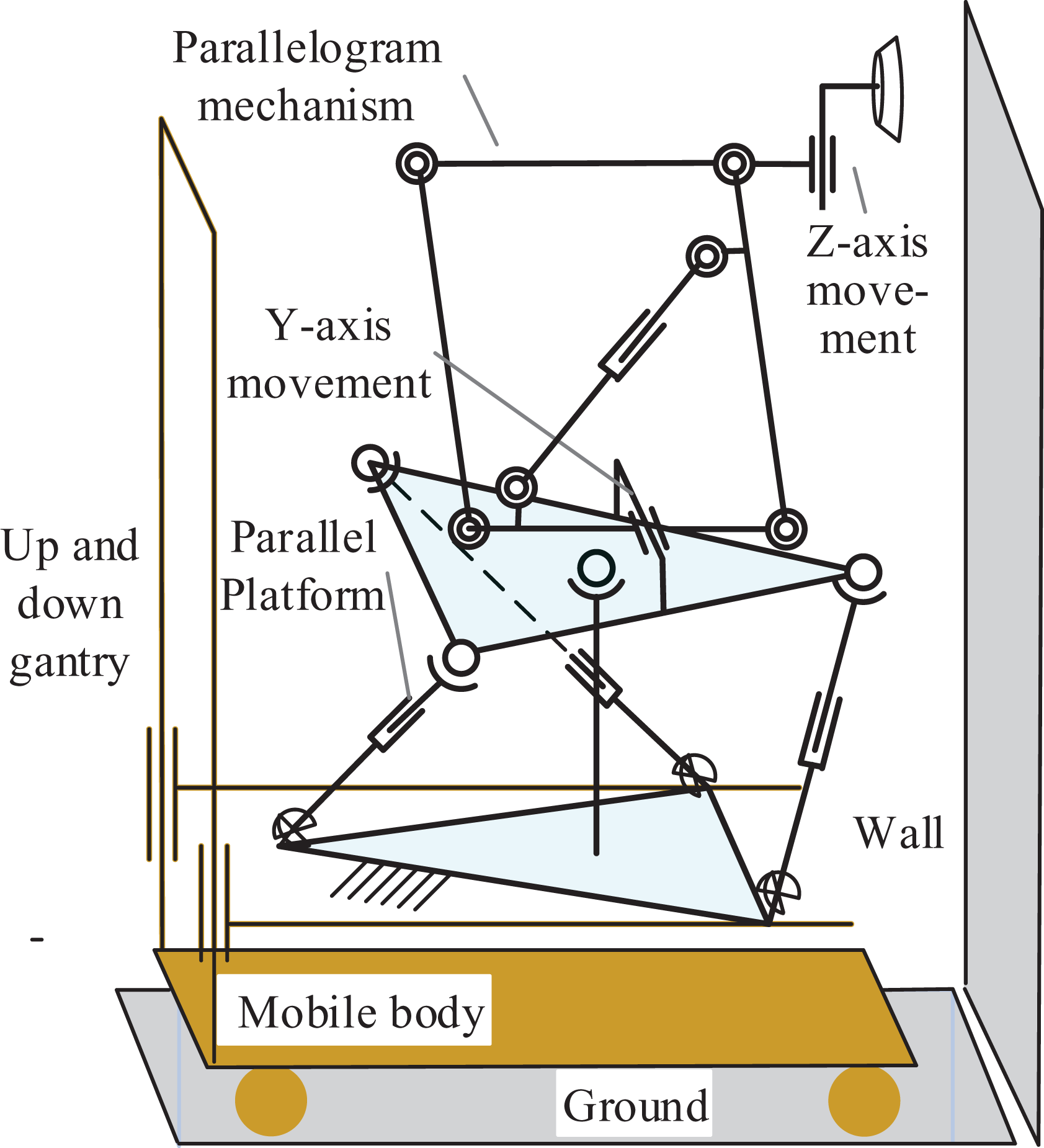
Serial and parallel robot mechanism diagram.
Moving body selection
The moving body of the mounting robot should have a large moving range and working height. The electric forklift is motion-wise flexible and has a high lifting capability, height-wise, which meet the requirements of the mobile body. Therefore, the TF20-35 electric forklift is modified for this case. The industrial control machine governs the advancement and lifting of the gantry. An ultrasonic distance measuring sensor is installed around the moving body, so that the moving body can avoid obstacles, ensuring safe travel. The electric forklift is shown in Figure 7, while the specific performance parameters of the moving body are listed in Table 2.
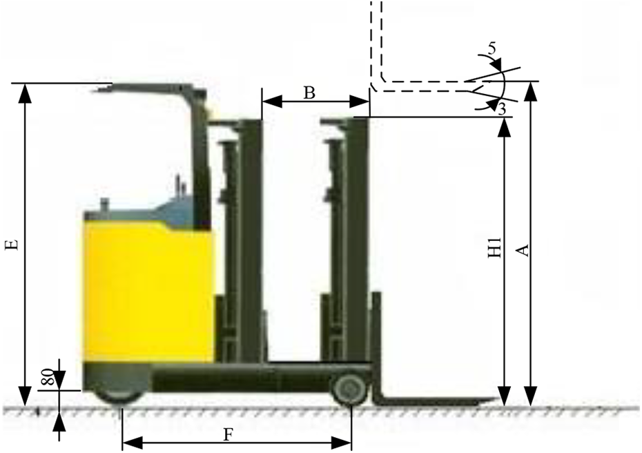
TF20-35 electric forklift dimensions.
TF20-35 performance parameters.

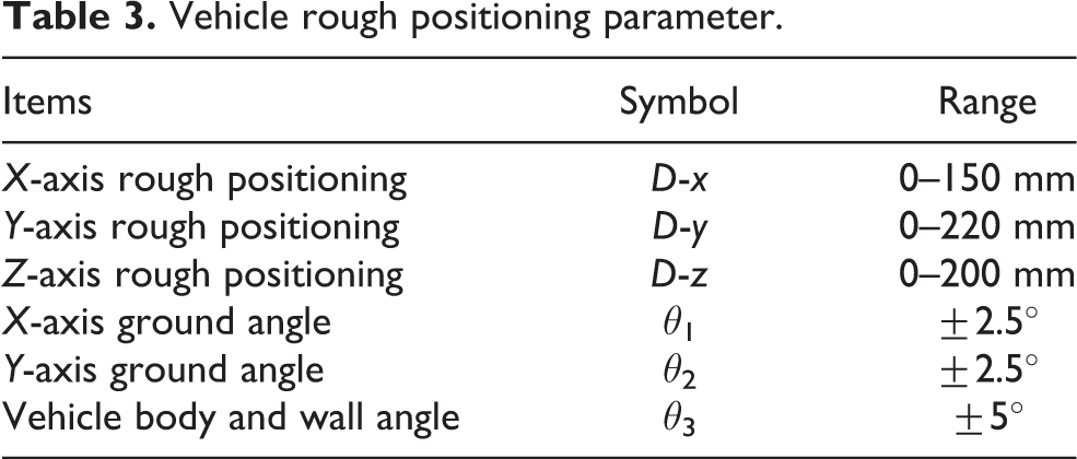
Based on the analysis of the vehicle body tilting condition, the rough positioning accuracy, and the ground slope condition of the vehicle body working environment, the relevant parameters of the vehicle body rough positioning are obtained, as the body is moving during the installation process (Table 3). The installation of the external cladding is completed by the rough positioning of the moving body and the precise positioning of the mounting robot. Therefore, the positioning accuracy of the moving body on the table is the minimum working range of the mounting robot, which provides a basis for the robot structural design.
Vehicle rough positioning parameter.
3UPS/S platform design
According to the analysis of the installation process and the research on the overall structural scheme of the robot, the robot system adopts the 3UPS/S three-degree-of-freedom parallel platform, as the first three degrees of freedom of the robot. They are used to adjust the spatial posture of the external cladding, to be installed. 3UPS/S (U: Hooke hinge; P: mobile pair; S: ball joint) three-degree-of-freedom parallel platform structure is shown in Figure 8. The structure includes static platform and moving platform, connected through a constrained branch and three drive chains. 17 Three Hooke hinges are installed on the static platform, whose positions constitute an equilateral triangle centered on the restraining branch. The center of the moving platform is connected with a fixed support rod, through the ball joint, to form a constrained branch of the platform. Three ball joints are mounted on the platform, whose positions form an equilateral triangle centered on the constrained branch. 18 The installation positions of the three Hooke hinges on the static platform and the three ball hinges on the moving platform correspond to each other. The three Hooke hinges and the three ball hinges are respectively connected by three telescopic electric pushrods. The driving components, constituting the platform, can drive the parallel-rotating platform to a specified posture. This is realized by controlling the expansion and contraction of the three electric pushrods. When the parallel platform is in the initial position, the equilateral triangle, as determined by the three ball joints on the moving platform, is opposite to the equilateral triangle corner, as determined by the three hammers on the static platform. The electric pushrod is in the middle of the stroke. The 3UPS/S parallel structure has four branches to support it, with excellent mechanical properties, making it very suitable for applications with relatively large loads, while it simplifies parallel decoupling operations. 19,20

Schematic diagram of the overall structure of the parallel platform.
Three-degree-of-freedom moving mechanism design
The function of the three-degree-of-freedom moving mechanism is to realize the positioning and installation of the external cladding. It is completed through the movement in three directions, after the parallel platform is leveled. The three-degree-of-freedom moving mechanism of the mounting robot includes a parallelogram mechanism and two moving pairs along the Y-axis and the Z-axis. The function of the parallelogram mechanism is to realize the motion of the mounting robot perpendicular to the wall, in the X-axis direction. The Z-direction coupling motion, generated during the movement, is compensated by the Z-direction moving mechanism. The mechanism ensures that the external cladding always maintains a vertical translation of the moving platform attitude. The Y-direction mobile system is directly mounted on the parallel platform, with an effective stroke of 220 mm. Since the operating platform allows for an operating space for the operator, the drive screw in the Y direction is placed below the platform. The Z-direction moving part function realizes the movement of the end effector, in the Z direction, while it compensates for the coupling movement of the parallelogram mechanism, in the Z direction. A schematic diagram of the obtained three-degree-of-freedom moving mechanism is shown in Figure 9.

Schematic diagram of the overall structure of the three mobile mechanisms.
The linear guide screw and servomotor of the Y-axis direction moving pair are directly mounted on the parallel platform, described above. The screw is located below the parallel platform, in order to save space. The movement in the X-axis direction is realized by the movement of the parallelogram mechanism, while the lower ends of the vertical two rods are respectively connected to the slide table of the Y-axis, through the rotating shaft. Both ends of the electrically actuated pistons are respectively connected to the rods of the four-bar mechanism and the Y-axis slide table, through the rotating shaft, serving as driving members of the parallelogram mechanism. The Z-axis slide is driven by the Z-axis servomotor, through the lead screw, while it moves along the linear guide, to achieve vertical movement, perpendicular to the moving platform. The parallelogram mechanism designed in this article can increase the movement space in the X direction. Then, the actuator, mounted on the upper end thereof, can be raised to a comfortable height for human operation, which benefits the human–machine cooperative installation operation.
The overall structure of external cladding installation robot
The above design of the overall mechanical structure of the installation robot completes the robot system design. The specific model of the installation robot and the overall physical form are as shown in Figure 10. In addition, in order to ensure the safety of manual operation, protective devices, such as guardrails and limit positions, should be designed around the operator workspace. Moreover, when installing the robot system, it is necessary to move the lifting device of the main body, so that the robot is raised to a certain height.

The external cladding installation robot: (a) the structure of installation manipulator and (b) overall appearance of installation robot.
External cladding installation tests
In order to verify whether the parameters and functions of the external cladding installation robot prototype meet the requirements of automated building external cladding installation, in an effort to experimentally improve the robot, a virtual test site is set up, to install and test the installation robot. According to the process characteristics of the dry hanging installation of the external cladding and the on-site inspection of the construction site, a construction environment simulation site is set up. The installation of the external cladding, in the virtual site, enables the automated installation of the building external cladding and it verifies the effectiveness of the proposed installation robot. 1. External cladding to be installed
A plate with dimensions of 600 × 800 mm2 and a thickness of 30 mm is selected as the main installation object, as shown in Figure 11(a). In addition, in order to verify the maximum size of the panel that can be installed on the external cladding installation robot, a plate of 1000 × 1500 mm2 is selected for the maximum size installation test, as shown in Figure 11(b). The height of the experimental site is greater than 5 m, which allows the operating machine to be lifted to the maximum height.

Installation of experimental plates: (a) plate 600 × 800 mm2 and (b) plate 1000 × 1500 mm2.
2. Construction of the main keel
According to “JGJ133-2001 Metal and Stone External Cladding Engineering Technical Specification,” a 50 × 50 mm2 angle steel is selected for the main frame structure and the subframe structure. According to the size of the external cladding and the gap between the installation external cladding and the carrying capacity of the frame, the design distance of the main frame is 810 mm, while the spacing of the secondary keel is 610 mm and 1510 mm, as shown in Figure 12.

The main/subframe structure.
3. Selection of pendants
The SE-type pendant is selected for the test pendant, as shown in Figure 13. Because of its unique structure, SE-type pendants can be easily removed, through the gap between adjacent external claddings, after installation. This brings great convenience to the maintenance and replacement of the external cladding, which is very suitable for the automated installation of external cladding.

SE-type combination pendant.
4. Installation test
The installation test is carried out using two types of plates. One has a size of 600 × 800 × 30 mm3 and a mass of 40 kg. The other has a size of 1000 × 1500 × 18 mm3 and a mass of 70 kg. The series-parallel robot performs the automated installation operation test, according to the following process: adsorption of external cladding; rough positioning of moving body-leveling of parallel platform; fast approaching installation position; parallel platform leveling again; slow positioning installation; installation completed, as shown in Figure 14. The test proves that the external cladding installation robot, developed in this article, can achieve the expected goal.
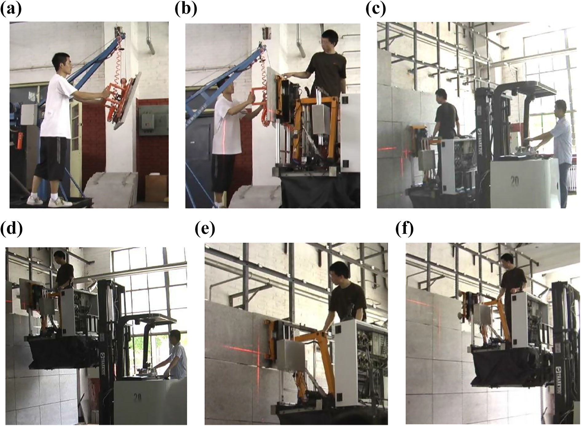
Robotic plate dry mounting: (a) plate hand assisted; (b) absorption plate; (c) body positioning; (d) body positioning; (e) plate positioning installation; (f) installation completed.
5. Installation accuracy test
In order to fully measure the positioning accuracy of the robot, the respective measurement should be carried out in three directions of X, Y, and Z, for different positions and loads, as shown in Figure 15. The end effector repeatedly moves to the specified target position during tests. The dial indicator measures the accuracy error of the target position, after each movement stops, along the X direction. The same method is used to measure the positioning accuracy in the Y and Z directions, providing the robot positioning accuracy. The robot positioning accuracy is under no-load and under load. The measurement data is shown in Table 5 and Table 6.

Robot accuracy measurement: (a) no-load measurement and (b) load measurement.
Measurement results (mm) of no-load target position (60, 100, 150).

Measurement results (mm) of load 35 kg target position (60, 100, 150).

Technical parameters of the external cladding installation robot system.

The technical parameters of the external cladding installation robot system, measured during the installation experiment, are listed in Table 6, verifying the feasibility of the robot structure design.
Conclusion
In this article, a full literature review on the research status quo and direction of construction robots is presented, especially the external cladding installation robots. The current research hot spots and existing problems of architectural robots are outlined. Through the analysis and comparison of the installation process of building external cladding, the robot construction process is established. It lays the foundation for the overall scheme design of the installation robot.
In this article, according to the functional requirements of the external cladding installation, the robot system adopts a mobile body structure to mount the manipulator. It realizes the installation of the external cladding in a large space, without the need to set up a scaffold. Aiming at the installation requirements of large-sized external cladding, an appropriate manipulator is developed. It is featured by a six-degree-of-freedom series-parallel hybrid mechanism. The manipulator has a high load carrying capacity and rigidity, while it can carry up to 70 kg. The form of a manipulator mechanism that adjusts the position, after adjusting the attitude, is proposed. It not only conforms with the installation process of the external cladding but also simplifies the system-motion calculation and control.
The robot for building external cladding installation, as developed in this article, provides automatic construction equipment for the building decoration industry. It adapts to the needs of special industries. It is domestic, to a certain degree, while it is capable of operating in complex construction environments. The robot brings change to the traditional manual and labor-intensive installation mode, while it gives solution to difficult realization of large-sized and heavyweight fragile external cladding, in the construction, without the need for scaffolding. It meets the operation requirements for diversification in building external cladding installation. In a word, the robot creates a new situation in the construction and decoration, while it lays the foundation for a subsequent series of multifunctional construction robots and applications.
Footnotes
Authors’ note
DY and YL are co-first authors of the article.
Declaration of conflicting interests
The author(s) declared no potential conflicts of interest with respect to the research, authorship, and/or publication of this article.
Funding
The author(s) disclosed receipt of the following financial support for the research, authorship, and/or publication of this article: This work was supported by National Natural Science Foundation of China (U1813222) and National Key Research and Development Project (2018YFB1306900).