
Abstract
Modeling and control for a novel coaxial ducted fan aerial robot in-ground-effect is presented in this article. Based on experiments using the ducted fan bench test, the fitting curve of the ground effect thrust of the ducted fan aerial robot at different heights is obtained. In addition, the flow field simulation results of the prototype with ground effect at different heights can be obtained using computational fluid dynamics software. A simplified model of the prototype for control can be designed based on several reasonable hypotheses that are established using blade element and momentum theory. To compensate for the disturbance associated with ground effect, a nonlinear disturbance observer is designed to estimate the disturbance, and control structure of the closed-loop system is composed of a nonlinear disturbance observer combined with a double-loop proportion–integration–differentiation controller. The results of several numerical simulations and experiments demonstrate the effectiveness of this controller structure. The performances of tracking trajectory and system stability are improved significantly, compared to the situation that the ground effect is not compensated for.
Keywords
Introduction
Given its vertical takeoff and landing capability, in addition to its high maneuverability, unmanned aerial vehicles (UAVs) are widely used in operating platforms for various tasks. In military applications, UAVs have the advantages of concealment, strong reconnaissance capability, and low cost. They can be widely used for military tasks such as reconnaissance and attack. In civilian applications, they can be used for communication relay, meteorological monitoring, disaster monitoring, and several other fields. With the increase in demand, the usage scenarios of UAVs have gradually changed from simple open environments to indoor and confined environments. This also implies that the movement and control of UAVs are changing from an environment-independent relationship to situations whereby the physical interaction with the environment must be considered. The main challenge when UAVs operate in confined spaces is proximity effects, such as ground effects. The proximity effect impacts UAVs and affects the flight performance of the system. In addition, in some situations, when the UAV is operated close to the object surfaces, the system becomes unstable. The UAV rotor blades drive peripheral airflow when they rotate. When the rotor approaches objects in the environment, the airflow interactions between the rotor and the surrounding solid boundary affects the free diffusion of the airflow, which is most pronounced in hovering and low-speed UAVs.
The study on the ground effect mainly focus on height control and aerodynamic analysis. 1 Initially, the study of ground effect was aimed at helicopters and there are several studies on ground effect for these aircraft. 2,3 Over time, there has been some progress in the study of the ground effect for fixed-wing aircraft. 4,5 In recent years, the study of the ground effect for multirotor UAVs has gradually emerged.
Most studies consider multirotor UAV control to avoid ground effect by keeping the aircraft as far away as possible from obstacles. However, the ground effect is inevitable when the multirotors are operated during near the object surface. For the landing and hovering of a multirotor with the influence of the ground effect, a dynamic linear controller is used, and the height is estimated using a Bayesian filter. 6 The adaptive controller and a height estimator are used to compensate for the disturbance caused by the ground effect of the multirotor, but it is worth noting that the measurements of an ultrasonic sensor are critical to the system. 7 The trajectory of the quadrotor landing is tracked by using a robust height controller. 8 The results indicate the performance in the presence of the ground effect has been improved for height tracking.
However, research on the ground effect of UAVs for ducted fan structure is limited. 9 Compared to open-rotor UAVs, the ducted fan aerial robot can operate in more confined, complex, and unknown scenes. Due to the existence of the duct, direct contact of the rotor blade with the outside world can be avoided; therefore, it has better safety performance. In addition, when the rotor blade size is the same, a ducted fan will generate an increment thrust compared to an open rotor due to the effect of airflow in the lip. 10 Given these advantages, a duct structure aircraft is more suitable for use in confined environments than open rotors.
To better estimate and compensate for ground effect, an in-ground-effect (IGE) model for motion control of aircraft is necessary. Given that the main operation considered in this article is hovering, the IGE model is steady state when the power is constant. The model can represent the relationship between the IGE thrust and the distance between the rotors and the ground surface. An accurate IGE model implemented into the controller design can improve the performance of the prototype.
Previous authors have obtained the IGE model of an aircraft by empirical aerodynamic analysis. Mahony and Hamel 11 used the approximation of the velocity ratio to estimate the rotor thrust variation IGE model based on the study of Prouty. 12 Cheeseman developed an empirical IGE model, and the validity has been proven in numerous experiments. 13,14 A quasi-steady IGE model for the helicopter was presented by Hayden. 3 Li et al. 15 presented a new IGE model for the quadrotor based on Cheeseman’s IGE model, which is based on the aerodynamic interference between the four rotors and introduces a coefficient to correct the ground effect model. However, these studies are all conducted on helicopters or multirotors, which is usually applied to a height of z > 0.5 R, where R denotes the radius of rotor.
Considering the special structure of the ducted fan aerial robot in this article, there will be aerodynamic interference between the two rotors of same ducted fan during the ground effect. The IGE model of the helicopter and the quadrotor are not suitable for the ducted fan aerial robot. As such, a ducted fan test bench is designed wherein the ground effect of the prototype is tested at different heights, and the thrust variation is analyzed. Compared to the previous IGE models, the contribution of this article is that an accurate IGE model was obtained with a wider effective range that is suitable for a coaxial ducted fan structure aircraft. The IGE model can be used to access the system performance and the prototype dynamics with ground effect. In addition, the partial ground effect is discussed and studied in this article. It occurs when the ducted fan aerial robot is close to the surface or obstacles in the environment, and only one of the ducts are under the influence of the ground effect, but not two. As far as the authors’ knowledge, the study of partial ground effects based on ducted structure aerial robot has barely been studied before.
In recent years, there have been several studies on the estimation of the external wrench by a nonlinear disturbance observer for a quadrotor, 16,17 which is suitable for estimating external disturbances. 18 However, disturbance observers have been used in a few instances to estimate the effect caused by the environment. A nonlinear disturbance observer is proposed in this article to estimate the disturbance caused by ground effect. Finally, based on simulations, the proposed nonlinear disturbance observer (NDO) combined with a double-loop proportion-integration-differentiation (PID) control structure is shown to effectively address the disturbance for improved closed-loop performance.
The contribution of this article mainly includes two parts. One is to propose an IGE model for a novel coaxial ducted fan aerial robot, which is different from the IGE model of the helicopter and the quadrotor. At the same time, the aerodynamic analysis and dynamic model of the prototype are considered. The other is to propose a control structure that combines a double-loop PID controller with a nonlinear disturbance observer to estimate and compensate for aerodynamic disturbance to guarantee good performance of our robot IGE. The proposed controller structure shows better performance than traditional PID controller in the presence ground effect.
The rest of the article is structured as follows: the aerodynamic influence of a ducted fan IGE is shown in the second section; the simplified dynamic model of the prototype is proposed in the third section; the nonlinear disturbance observer is designed in the fourth section; simulation analysis of the prototype in some different situations are presented in the fifth section; some experimental results are presented in the sixth section; the seventh section presents the main conclusions and considers future prospects of this research.
Aerodynamic influence of ground effect on the prototype
In previous studies, we have conducted a series of related work on ducted fan aerial robots. 19 –21 With the continued progress of the research, the structure of the prototype is constantly changing. Based on the continuous optimization and the attempt to perfect the structure of the prototype, the resulting novel prototype mechanism is shown in Figure 1.

Novel prototype mechanism.
Similar to the multirotor UAV, the pitch and yaw moments of the aerial robot are generated by the speed difference between the front and rear ducted fan rotors. The rolling moment of the entire machine is generated by the control surface at the bottom. In addition, the ducted fan aerial robot presented in this article can carry manipulators and other tools for different tasks, to achieve hovering observations and operations close to an object in a confined environment.
Analysis of aerodynamic performance considering ground effect
When the prototype generates ground effect, the rotor will generate an increment thrust with a constant power. The increment thrust is tightly associated with the distance from each rotor to the object surface. In this article, when the prototype hovers in the near-ground region, due to the ground effect, the thrust changes, which affect the stable state of the prototype. This effect is also closely related to the distance from the ground surface to each of the ducts. It is necessary to experimentally obtain this relationship.
Due to the symmetry of the prototype structure, a single ducted fan with a coaxial rotor is used instead of the prototype for testing. Considering that the distance between the front ducted fan and the rear ducted fan is sufficiently large, the aerodynamic interference between them can be ignored. The complete duct test bench is shown in Figure 2.

Ducted fan test bench.
In Figure 2, it is observed that the test bench is made of aluminum alloy and the total weight is 50 kg. As a result of the weight, when the bench is in normal operation, it will be almost free from external interference, which can effectively ensure the accuracy of the data obtained by the test. The force sensor is applied for directly measuring the thrust generated by the ducted fan. The thrust and torque of the rotors are measured by the two-component balance, and the speed of the rotor is measured by the rotary encoder.
In this article, a constrain board is used instead of the ground surface. The change in the height of the ducted fan from the ground is represented by the change in the distance between the constrain board and the ducted fan. The experimental IGE model and several empirically IGE models are shown in Figure 3.
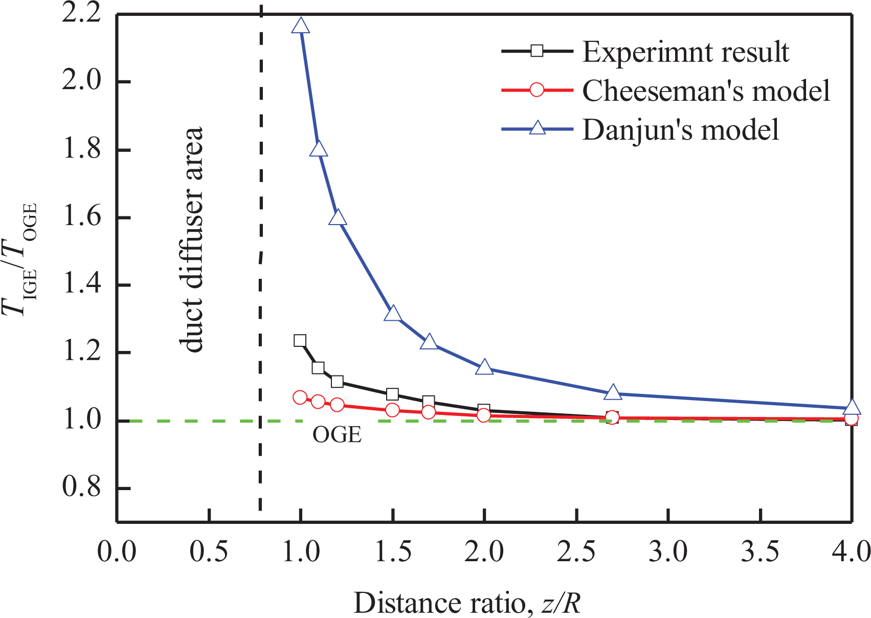
Comparison of some different IGE model. IGE: in-ground-effect.
The thrust ratio between IGE and out of ground effect (OGE) for constant power at different distance ratios is shown in Figure 3. In this study, z denotes the height from the center of the upper rotor to the ground surface, and R denotes the radius. Based on several experiments at different distance ratios, z/R, the fitting curve of the thrust ratio between IGE and OGE for constant power is obtained, the form of the fitting model is
The form of the fitting model is
Analysis of flow field mechanism for ground effect
In “Analysis of aerodynamic performance considering ground effect” section, the thrust ratio at different heights for the ground effect is obtained. Considering the special structure of our prototype, it is different from the quadrotor. During the ground effect, there is mutual interference between the duct, the rotors, and the ground. It is necessary to analyze the flow field for the IGE for different heights of the prototype. Given that the distance between the front duct and the rear duct is sufficiently large, the flow field interference can be ignored. A single ducted fan with a coaxial rotor is used instead of the prototype for flow-field analysis. The flow field of the prototype at different heights can be analyzed using the computational fluid dynamics (CFD) software, and the analysis results are presented in Figure 4.

Velocity cloud of ducted fan with ground effect at different heights: (a) z/R = 2.7; (b) z/R = 1.7; (c) z/R = 1.2; (d) z/R = 0.9.
Figure 4 shows that with the decrease in the height from the ground (from (a) to (d)), the deflection of the downwash flow increases and the effective flow area Ae at the duct diffuser area decreases. The airflow diffusing outward from the ducts interacts with the airflow returning from the ground, and a ground vortex is generated under the duct. When the relative height z/R is reduced, the ground vortex becomes more intense. In addition, when the relative height z/R is reduced to a certain value, the airflow diffusing outward from the tips will interact with the airflow returning from the ground, which generates a tip vortex. The ground vortex and tip vortex adversely affect the aerodynamic stability of the prototype. Given that a prototype needs to perform near-the-ground hovering operation, the controller should be designed to maintain its stability.
Ducted fan aerial robot IGE dynamics
Ducted fan aerial robot rigid body dynamic
To design the controller for our prototype to compensate for the ground effect, we need to obtain a system dynamic model. The states and the input variables of the ducted fan aerial robot are shown in Figure 5. There are several reported studies on the modeling of the duct structural aerial robot. 10,24 However, the structure of our prototype is very different from these models. In our previous study, the second generation of the ducted fan aerial robot was modeled. 19 The modeling method was based on blade element and momentum theory. The prototype structure and modeling method used in this article are similar to that of Zhang et al., 19 but there are some differences between them. The most important difference is that the rolling moment of the prototype is generated by the control surface at the bottom, whereas the rolling moment of the model in Zhang et al. 19 is generated by the cyclic pitch.

State and input variables of prototype.
Given that the main operation of the aerial robot in this article is hovering, the aerodynamic drag can be ignored. Considering the front duct as an example, the resultant force and torque of the system are written as equations (1) to (3). In the interest of brevity, the details of the derivation are not provided.
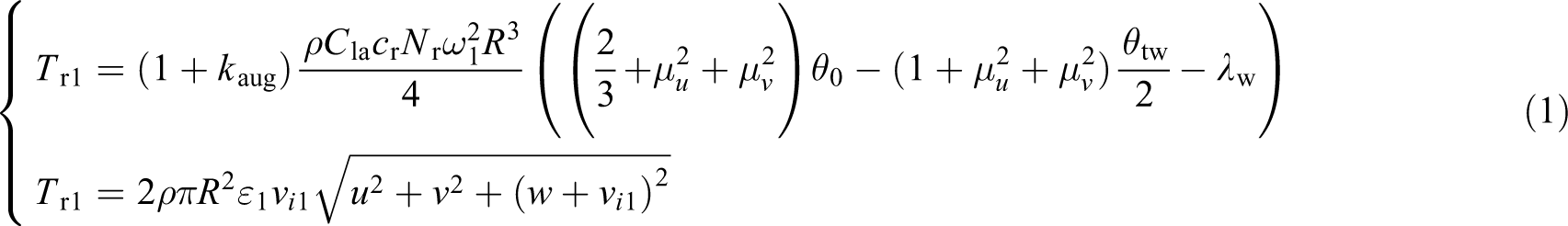

where

where j = 1 for the upper rotor and j = 2 for the lower rotor,
Simplified model of ducted fan aerial robot
The system model obtained in “Ducted fan aerial robot rigid body dynamic” section is too complicated in its current form and its solution involves solving many unknown parameters. Considering that the main condition of the prototype is used in low speed, the values of

Then, equation (1) can be simplified as follows
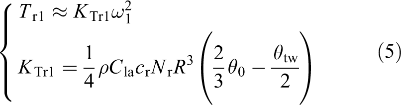
where K Tr1 denotes the overall parameters of the thrust characteristics of the upper rotor. The moment simplification of rotors is similar to the simplification of the force; the roll moment and pitch moment are expressed as


where K LMr1 and K LMr2 are the aerodynamic moment coefficients of the two rotors, respectively. From the symmetry of the prototype structure, the moment coefficient in the roll and pitch directions is equal. The reactive torque of the prototype can be written as follows

where K Qr1 and K Qr2 are aerodynamic reaction torque coefficients of two rotors, respectively. The values of K Trr1, K Trr2, K LMr1, K LMr2, K Qr1, and K Qr2 can be determined by system identification. Via the process of simplification, the related expressions between the resultant thrust, the resultant moment, and the four rotors speed can be obtained as follows
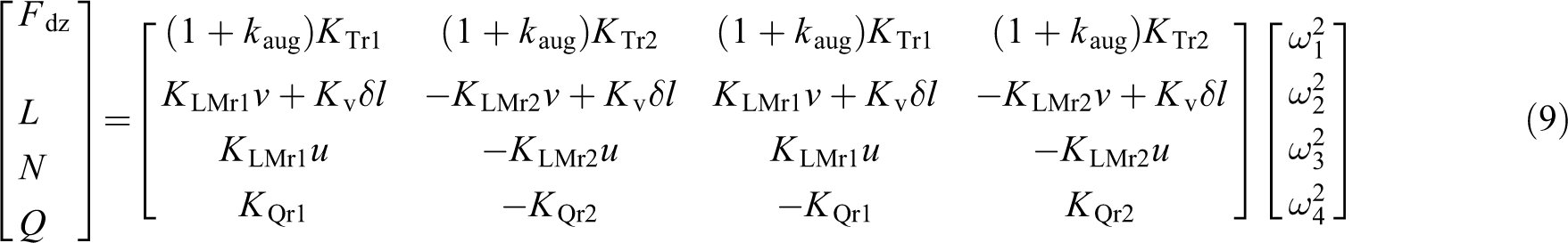
where δ is the control surface deflection angle,
Ducted fan aerial robot dynamics for ground effect
Using equation (9), the thrust model of our prototype without ground effect is obtained. However, when the prototype is hovering close to the ground, the relationship between the resultant thrust, the reaction torque, and four rotors speed is no longer valid. The thrust model is rewritten as follows

where f GE(z) denotes the ground effect factor, which can be used to obtain the increment of the system’s thrust. In this article, f GE(z) depends on the height z of each ducted fan to the ground surfaces.
Using the modeling process, the motion state of the system includes the line velocity, angular velocity, and three Euler angles in the body frame. Therefore, the system state is written as

To decouple the different channels of the system, we design a double-loop PID controller, which is widely used as a baseline control scheme. 25 The attitude and position controllers are designed as follows

where ex
, ey
, and ez
are the position errors of three directions, respectively.

where

where

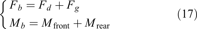
where K mix is the mix control matrix. When gravity isn’t considered, the resultant force of a system in the body frame is expressed as

Considering gravity, the resultant force and resultant moment can be written as
Nonlinear disturbance observer design for ducted fan aerial robot
The body frame of prototype and inertial frame can be shown in Figure 5. The OGE model input can be written in terms of the force


R nb is the rotation matrix form the body frame to the inertial frame, expressed as
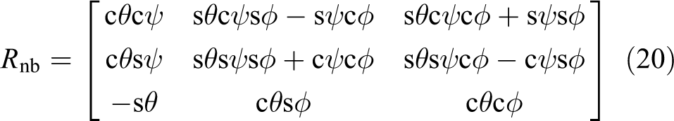
where m denotes the prototype’s mass, g denotes the gravity acceleration,

where

and
The nonlinear disturbance observer can be designed as

where

The observer error is defined as

Therefore

Equation (26) can be written as

From equation (27), we can find that the choice of

Taking the time derivative of equation (28), we get the following

By substituting equation (29) into equation (23), we obtain

The structure of the nonlinear observer can be seen in Figure 6, which can be written as


Structure of the nonlinear observer.
The nonlinear observer is designed using equation (31) to estimate the ground effect. We can define an auxiliary function as

c denotes a constant observer gain. The

The globally asymptotic stability of the observer can be proven in Chen et al. 27 The closed-loop system complete control structure can be seen in Figure 7.

The complete control structure of the system: (a) outer loop control and (b) with the NDO inner loop system G.
Simulation results
Simulation of ground effect
The simulations are based on the simplified model of the prototype and the thrust change at different heights for the ground effect. Due to the structural symmetry of the ducted fan aerial robot, when the front and rear ducts hover at the same height to produce the ground effect, only the disturbance force along the z-axis should be considered, and the disturbance force of the x and y axes is ignored. Therefore, some of the vectors in the fourth section can be written as
To obtain the simulation results for the ground effect of a double-loop PID controller and a PID controller combined with the NDO, the desired trajectory should be given. In this article, we set up the desired trajectory in which the aerial robot fly to 0.6 m height and moves to x = 1 m and y = 0.8 m. Considering that we need to analyze the impact of the ground effect on the simulation due to height variations, we set the prototype to continue to track a sinusoidal trajectory in the height direction after flying from 0 m to 0.6 m. The upper limit height is 0.8 m and the lower limit height is 0.4 m, the reference input of the three directions are written as

The position tracking results of the closed-loop system in two different conditions are shown in Figure 8.

Tracking results of PID controller without ground effect and with ground effect: (a) tracking results of well-tuned PID parameter without ground effect and (b) tracking results for the same PID control parameter with ground effect.
Figure 8(a) and (b) shows the simulation results of the PID controller with and without ground effect, respectively. Noticing that in these two scenarios, the desired trajectory, the controller structure, and the controller parameters are all same. Compared to OGE, the double-loop PID controller cannot compensate for the disturbance caused by ground effect, which is a larger tracking error for the height. The maximum tracking error for the height is 6 cm. It is worth noting that both the NDO and the ground effect compensator are deleted in this simulation.
Given that the NDO is independent of the reference trajectory, the NDO and ground-effect compensator are designed, as shown in Figure 7(b). The NDO can be applied to estimate force and moment caused by the ground effect, and the measurement results are subtracted from the command PWM sent to the actuator. The tracking results for the PID combined with the NDO control structure with ground effect are shown in Figure 9. It is worth noting that both the NDO and ground effect compensator are used for this simulation.
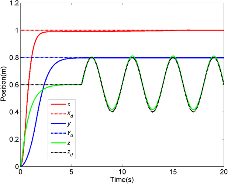
Tracking results of the PID combined with the NDO control structure with ground effect.
It is evident from Figure 9 that the maximum tracking error for the height is 1.8 cm. Compare to the PID control, the PID combined with the NDO control structure can effectively compensate for most of the disturbance caused by ground effect and reduce tracking error at different heights. The residual tracking error may include the ground effect compensator error.
In addition, the tracking error of the x and y directions is small and almost unchanged in Figures 8(a) and (b) and 9, which also show that the ground effect has little effect on the x and y directions of the ducted fan aerial robot. The first reason is that the x–y plane final position is a fixed point. The second is that due to the structural symmetry, there is no height difference between the front and rear ducts, which is insufficient for the generation of a disturbance moment that affects the x and y directions.
Simulation for partial effect
In “Simulation of ground effect” section, we discussed the situation where two ducts of the prototype are subjected to ground effects. Given that the prototype is suitable for use in complex environments, a special phenomenon may also occur. In this situation, the front ducted fan with the ground effect and the rear ducted fan without the ground effect can be called the partial ground effect. In this situation, the front ducted fan with the ground effect and the rear ducted fan without the ground effect are what we call the partial ground effect. According to the literature, 28 the relationship between the thrust increment and the duct area under the ground effect is approximately considered to be linear. Figure 10 shows the prototype under the partial ground effect.

Ducted fan aerial robot under the partial ground effect.
As we can see from Figure 10, in this situation, the object under prototype is an obstacle or a step; owing to the presence of ground effects, the front duct receives a thrust increment ΔT ge, which generates a counter-clockwise tilting moment M ge about the y-axis and keeps the prototype away from the flat surface. This partial ground effect may induce a significant disturbance, so the PID combined with the NDO control structure can be used to compensate for disturbance. The simulation condition is set as follows: the prototype starts at the position of the centroid at x = 0, moves along the x-axis, sets the obstacle at x > 1.75 m, and sets the reference trajectory to x = 2.2 m. When the prototype reaches its destination, the front duct is above the obstacle and the rear duct is suspended. The simulation diagram is shown in Figure 11.

Prototype hovering in a point under the partial ground effect.
The response results obtained in the simulations for a comparison of the controllers are shown in Figure 12.

Hovering under partial ground effect: comparison of controllers (z/R = 3): (a) tracking result of the x position and (b) response of pitch angle.
As observed in Figure 12, a black line is set as the desired trajectory for the x-coordinate, and the brown line is set as an obstacle initiation. When the value of the x-coordinates is over the brown line, the prototype will produce the partial ground effect. It is evident from Figure 12 that compared to OGE, the other two controllers cannot completely compensate for the disturbance caused by the partial ground effect. However, for partial ground effects at z/R = 3, the prototypes of two control structures can eventually maintain stable hovering. In addition, compared to the PID controller, the PID combined with the NDO control structure can more effectively compensate for the disturbance, and the steady-state error of the position tracking is also smaller.
To evaluate the impact of partial ground effects on the performance of the prototype, the relative distance is reduced to z/R = 2, and the simulation is conducted under the same conditions as in Figure 12. The simulation results of position tracking and pitch angle response can be seen in Figure 13.

Hovering with partial ground effect: comparison of controllers (z/R = 2.0): (a) tracking result of the x position and (b) response of pitch angle.
Comparing Figure 13 to Figure 12, it is evident that the tracking error is larger, and the pitch angle is also greater under both controllers. This indicates that the partial ground effect will have a more serious impact when the relative distance z/R is reduced. As observed in Figure 13(a), the PID controller cannot track the desired trajectory and will cause repeated oscillations that lead to prototype unstable. Compared with the OGE, the PID combined with the NDO control structure also cannot track the desired trajectory accurately, and there is a steady-state error. However, the prototype can still achieve stable hovering.
Experiments
After repeated debugging, the proposed control structure that combines a double-loop PID controller with a nonlinear disturbance observer in this article is implemented in the open-source flight control framework auto pilot mega (APM), and the main hardware composition of the experimental prototype is shown in Figure 14. The entire system consists of an integrated flight control module, airborne auxiliary sensors, a wireless data chain module, and a remote console. The integrated flight control module can meet the needs of the secondary development of the flight control algorithm and can be very convenient to implement the control algorithm proposed in this article. The airborne auxiliary sensors can improve the system’s perception and provide high-precision data such as position and attitude. The wireless data chain module is used for real-time communication between the prototype and the ground station. The remote console is mainly used for remote control and communication of the prototype.

The main hardware composition of the experimental prototype.
The entire experimental environment is conducted mainly indoors. During indoor experiments, the position information of the prototype can be obtained from the optical flow module. However, due to the limitations of the vision algorithm and camera hardware, the optical flow module has low measurement accuracy and can only measure relative position shifts without being able to obtain reliable global coordinates. Therefore, we use OptiTrack motion tracking system for position measurement of prototype in indoor environment. The system is a professional six degrees of freedom object tracking, high-precision optical device that supports real-time and off-line processing of six degrees of freedom data of the object and is a standard optical attitude measurement system tailored for engineering, scientific research, and other applications, as shown in Figure 15.
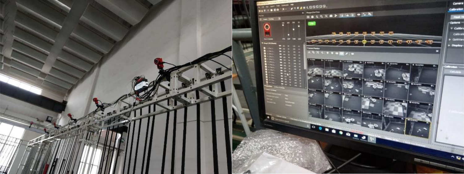
The OptiTrack motion tracking system.
At the same time, when the prototype is equipped with the required hardware as shown in Figure 1, let it hover in the experimental field which is equipped with the OptiTrack motion tracking system. When the prototype is experimented without ground effect, the double-loop PID control structure is used to control the prototype and gives a ramp reference signal 1.9–1.4 m in the height direction at 9–14 s. When the prototype is experimented with ground effect, two different control structures are used to control the prototype and give a ramp reference signal 0.9–0.4 m in the height direction at 9–14 s. The experimental results are shown in Figures 16 to 18.

Experimental tracking results of well-tuned PID parameter without ground effect.

Experimental tracking results of well-tuned PID parameter with ground effect.

Experimental tracking results of the PID combined with the NDO control structure with ground effect.
It can be seen from Figures 16 to 18 that the experimental results are similar to the simulation results. Compared to OGE, the double-loop PID controller cannot compensate for the disturbance caused by ground effect, which is a larger tracking error for the height, the maximum error is 0.085 m and the RMSE is 0.0382 m. Compared to the PID control, the PID combined with the NDO control structure can effectively compensate for most of the disturbance caused by ground effect and track the height command more accurately at different heights, the maximum error is 0.046 m and the RMSE is 0.0214 m.
At the same time, as known from the simulation results Figures 12 and 13, the difference between the two control structures at z/R = 3 is not great, so to highlight the practical effect of comparing the two control structures, a wooden board parallel to the ground is placed at a distance of z/R = 2 below one ducted fan when prototype hovering at 23–29 s, and experiments are carried out for two control structures for the prototype, respectively. The experimental results of evolution of the prototype pitch angle are shown in Figure 19, where the brown rectangular background represents the wooden board is placed below one of the ducted fan.

The experimental results of prototype hovering with partial ground effect: comparison of controllers.
As can be seen from the experimental results in Figure 19, the experimental results are similar to the simulation results of Figure 13(b). The PID controller combined with NDO control structure has a smaller pitch angle and smaller system oscillation amplitude in the presence of partial ground effects than the double-loop PID control structure and ultimately returns the prototype to a stable state. Experimental results show that the control structure of the PID controller combined with NDO control structure can effectively compensate for the disturbance caused by partial ground effects. The reason for the larger pitch angle in the experimental results compared to the simulation results is the presence of wind gusts and other external noise disturbance under the experimental conditions.
Conclusions
Considering a ducted fan aerial robot hovering near the ground, disturbance can occur due to the generation of ground effect. The aerodynamic performance and flow field of the prototype are analyzed at different heights, and a simplified model of the prototype that can be used for control is established. Based on the prototype model, a PID combined with the NDO control structure is designed, and the tracking and stability performance of the prototype with ground effect and partial ground effect situations are analyzed. According to some simulation and experimental results, it is demonstrated that the PID combined with the NDO control structure can be used to compensate for ground effect.
There are still some areas that should be investigated further with respect to the proposed disturbance observer. For instance, when the ducted fan aerial robot needs to operate in a more restrictive environment, the PID combined with the NDO control structure may not maintain steady hovering of the prototype, and a more suitable control structure should be found. However, we can optimize the disturbance observer architecture to address different problems. At the same time, the uncertainty-risk situation also should be considered as a study plan for future. 29,30 Moreover, the ducted fan aerial robot in channel effects and the influence due to changes in the aerodynamic parameter can also be studied in the future.
Footnotes
Declaration of conflicting interests
The author(s) declared no potential conflicts of interest with respect to the research, authorship, and/or publication of this article.
Funding
The author(s) disclosed receipt of the following financial support for the research, authorship, and/or publication of this article: This research is supported by the National Natural Science Foundation of China (No. 51505031).