
Abstract
Wheeled walking mechanism has the advantages of high mobility and low rolling resistance, but it is easy to sink and slip when working in soft and muddy terrain. Tracked walking mechanism has the advantages of high passability and stability, but it has the problems of difficult steering and slow walking speed. In order to make the walking mechanism possess a combination of passability, stability, and mobility, a coordinated variable wheel-track walking mechanism was designed. The coordinated variable triangle track can change the landing area through the deformation structure to improve the ability of the walking mechanism to adapt to different terrains. The kinematics equation of the wheel-track walking mechanism was established, and the front wheel steering angle equation during motion was derived. Based on RecurDyn software, the motion simulation of the walking mechanism was carried out under the conditions of straight walking and turning on the flat ground, climbing hillsides, and crossing ditches. The simulation results show that the coordinated variable wheel-track walking mechanism has the mobility of wheeled walking mechanism and the passability and stability of the tracked walking mechanism. The stability and climbing ability of the wheel-track walking mechanism was better when the coordinated variable triangle track in the stretch state, and the mobility and steering ability was better in the contraction state.
Keywords
Introduction
With the development of economy and the demand of society, various kinds of walking mechanisms adapted to different kinds of terrain have sprung up, which can be roughly divided into leg type, track type, wheel type, compound type, and so on. Legged walking mechanism has strong adaptability and obstacle resistance ability, but its structure is too complex, it has some shortcomings such as low moving efficiency and difficult control. 1 –3 Wheeled walking mechanism has the advantages of strong bearing capacity, fast-moving speed, simple control, and flexible steering. However, when working in soft, muddy, snow, and other special terrain, the tire will sink and slip. Tracked walking mechanism has strong obstacle-crossing performance, high passing performance, but its walking speed is slow, and the wear of track is serious when turning. 2 –4 Compound walking mechanism has many sets of transmission systems, which are suitable for some special environments, but its structure and control are complex. 2 –6 An underactuated variable structure crawler robot is designed in the study by Zhang et al., 7 which improves the obstacle surmounting performance of the crawler mechanism to a certain extent, but it does not solve the problems faced by the crawler mechanism. Variable structure track mostly involves the problem of state constraint. A method is proposed to deal with the problem of state constraint of underactuated system in the study by Chen and Sun. 8 It can be used for reference in the control problem of variable structure track.
A kind of wheel-track walking mechanism was designed for improving the passability and stability in complex terrain. The front wheel of the wheel-track walking mechanism is common tire and the rear wheel is coordinated variable triangle track. While retaining the mobility of the wheeled walking mechanism, the passability and stability of the walking mechanism are improved. 9 The coordinated variable triangular track can change the landing area, which solves the problem of too slow walking speed and too large steering resistance. Figure 1 is a schematic view for the structure of a coordinated variable wheel-track walking mechanism. The wheel-track walking mechanism is different from the traditional walking mechanism in the past. It can change the structure of the track according to different working conditions, and then it can cross the obstacles purposely. The key of this design is how to determine the size of the landing area before and after the change of the coordinated variable triangular track. We determined the length of the track on the contraction state by calculating the maximum pressure that the road can withstand when the walking mechanism is unloaded and determined the length of the track on the stretch state by calculating the maximum pressure that the road can withstand when the walking mechanism is full loaded. Then assist the verification through simulation. In addition to the difficulty of the design of the coordinated variable triangular track, the relationship between the steering angle of the front wheels and the speed of the two tracks is also a problem to be solved. The simulation results show that the design is reasonable and feasible.

Structure of a coordinated variable wheel-track walking mechanism.
Structure and design of wheel-track walking mechanism
Structure of wheel-track walking mechanism
In this design, the front wheel is designed as common tire for reducing the steering resistance and improving the mobility of the walking mechanism. At the same time, it solves the problem of heavyweight and low mobility of the walking mechanism caused by the track.
Because the load of the walking mechanism is mainly in the rear axle, and the load on the rear wheel will change greatly under the condition of no load and full load, the coordinated variable triangular tracks are adopted in the rear wheels to improve the walking mechanism’s passability and load performance. The triangular track design is coordinated and variable. It can control the expansion of the telescopic hydraulic cylinder according to the terrain, and change the landing area of the track, so as to control the mobility and passability of the walking mechanism in harmony. 10 –14 As the landing area of the track becomes smaller, the resistance of the ground to the track becomes smaller, the steering torque becomes smaller, and the mobility of the walking mechanism is improved. As the landing area of the track becomes larger, the stability of the walking mechanism becomes higher, the pressure between the track and the ground is reduced, and the passability of the walking mechanism becomes better. The coordinated variable triangular track can control the expansion and contraction of the telescopic hydraulic cylinder according to the change of the walking mechanism’s load, realize the change of the landing area, and meet the load performance and improve the mobility at the same time. Figure 2 is a schematic view for the stretch state and contraction state of the coordinated variable triangular track.

(a) Stretch state and (b) contraction state of the coordinated variable triangular track.
Design of wheel-track walking mechanism
According to the specifications, dimensions, air pressure, and load standards of GB/T 2977-2016 truck tires, the light truck tires of type 5.50R13LT were selected.
The design of coordinated variable triangular track is the key to the design of this wheel-track walking mechanism. The main components of coordinated variable triangular track include integral bracket, swing bracket, telescopic hydraulic cylinder, slider, driving wheel, supporting wheel, tension wheel, guiding wheel, and tension device. As shown in Figure 3, the integral bracket, the swing bracket, the slider, and the telescopic hydraulic cylinder are connected together to form the deformation mechanism of the coordinated variable triangular track. The integral bracket and the swing bracket are articulated together. One end of the telescopic hydraulic cylinder rod body is connected with the integral bracket, and the other end of the cylinder body is connected with the slider. The inner part of the swing bracket is a hollow cavity and the slider can slide in the cavity. When the telescopic hydraulic cylinder is in telescopic motion, it will drive the slider to slide in the hollow cavity of the swing bracket. At the same time, the slider will force the swing bracket to swing around the articulated center, which will lead to changes in the landing area of the track.

Schematic of deformation mechanism in the (a) stretch state and (b) contraction state.
Track width is determined by the average grounding pressure, and the two are inversely proportional. The commonly used empirical formulas are as follows

where b is the track width, mm, and W is the rear axle load, N. The rear axle load W may be taken as 24,000 N at full load. b = 251.8–307.8 mm can be obtained from equation (1) and the track width b may be taken as 300 mm.
Track gauge is the distance from left track to right track and it is generally proportional to the width of the track. The commonly used empirical formulas are as follows

where d is the track gauge, mm. d = 1050∼1350 mm can be obtained from equation (2) and the track gauge d may be taken as 1200 mm.
The grounding length of track should be determined according to the average grounding pressure and the track width. Theoretical formulas are as follows

where L 0 is the grounding length of track, mm, and p is the average grounding pressure, kPa. The average grounding pressure of construction machinery is 30–70 kPa and the average grounding pressure p may be taken as 50 kPa.
When fully loaded, the rear axle load W may be taken as 24,000 N. The coordinated variable triangular track is in the stretch state, and the grounding length L 0 = 800 mm can be obtained from equation (3).
When no load, the rear axle load W may be taken as 18,000 N. The coordinated variable triangular track is in contraction state, and the grounding length L 0 = 600 mm can be obtained from equation (3). 15,16
The coordinated variable triangular track gear train includes driving wheel, supporting wheel, guiding wheel, and tensioning wheel. The driving wheel is mounted on the top of the integral bracket to drive the track forward. Three supporting wheels, two mounted on the integral bracket and one mounted on the swing bracket, support the weight of the whole track and transfer the weight of the walking mechanism to the ground. The guide wheel is mounted in the front of the integral bracket to support the track and to ensure that the track links are wound with the gear train in the course of movement. The tension wheel is mounted on the tension bracket to ensure the proper tension of the track. 15,17
Kinematics analysis of wheel-track walking mechanism
When the wheel-track walking mechanism steers, the front wheels conform to the Ackerman steering principle, but the tracks need to conduct differential steering according to the front wheels angle. We need to deduce the relationship between the front wheels’ angle and the rotation speed of the track driving wheels. In order to deduce this relationship and study the kinematics relationship of wheel-track walking mechanism in horizontal plane, the kinematics model of wheel-track walking mechanism during motion was established. 13,18 –22 The kinematics model only considers the kinematics relationship of the vehicle, but does not consider the dynamic relationship that affects the motion. For the convenience of research, the following assumptions are made to facilitate the construction of the model: (1) The wheel-track walking mechanism is assumed to have planar motion, without considering the vertical motion, pitch, and roll of the walking mechanism; (2) the track does not change the state of stretch and contraction, that is, the length of the track does not change during motion; and (3) the wheel-track walking mechanism is low-speed driving, and the lateral displacement is zero.
The motion state of wheel-track walking mechanism is mainly composed of coordinate


Plane of wheel-track walking mechanism motion relation. Note:
The following equations can be obtained from geometric relations in Figure 4

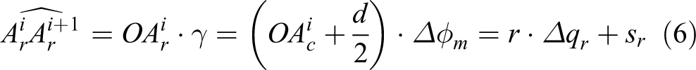
where r is the radius of the driving wheel of track,
Adding equations (5) and (6), we get

Substituting from equation (4) into equation (7), and dividing both sides by Δt. At the same time, taking the limit of Δt, we get

Subtracting equation (6) from equation (5), we get

Substituting from equation (4) into equation (9), and dividing both sides by Δt. At the same time, taking the limit of Δt, we get

Making a perpendicular crossing point O on the bottom edge
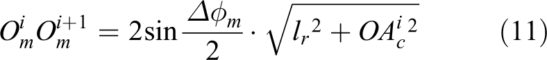


Substituting from equation (12) and


Substituting from equations (15) and (16) into


Taking the limit of Δt for equations (12) and (13), and substituting from equations (16) and (17) into equations (12) and (13), we get

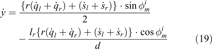
The equations of kinematics model are equations (10), (18), and (19).
The following equations can be obtained from geometric relations of triangle

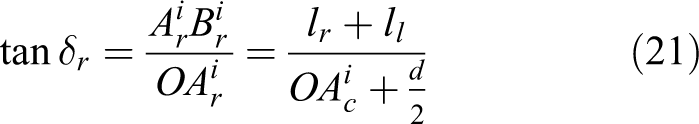
Substituting from equations (8) and (10) into equations (20) and (21), we get


Equations (22) and (23) are the equations to be satisfied for the steering angles of the left-front wheel and the right-front wheel of the wheel-track walking mechanism during motion. The equations are the theoretical basis of steering coordination of wheel-track walking mechanism
Motion simulation based on RecurDyn
Creation of simulation model
RecurDyn is a new generation of multi-body dynamics simulation software and has a toolbox to create a track subsystem, so it is more suitable for the motion simulation analysis of various tracked walking mechanisms. The software uses recursive algorithm to simulate and solve, with high efficiency and great stability. 18,23 –26 And different from other multi-body dynamics simulation software (e.g. Adams), RecurDyn software has its own tire and track module, which is more suitable for the simulation research of wheel-track walking mechanism.
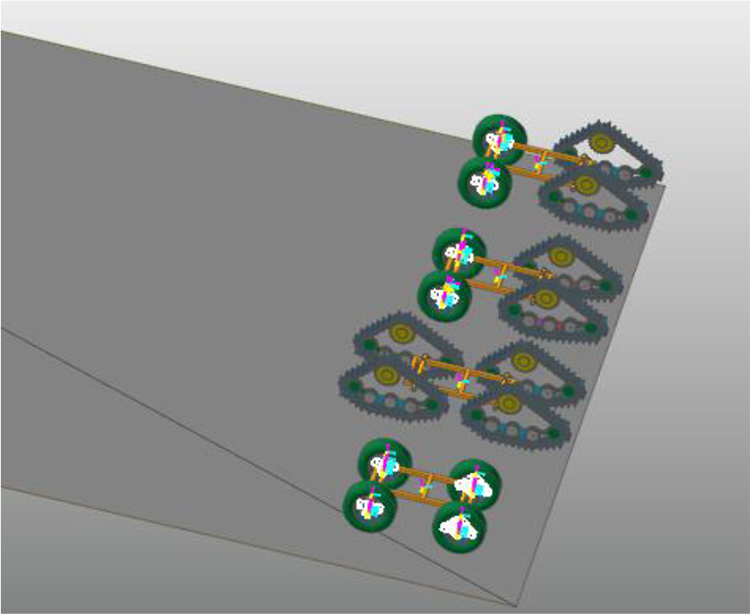
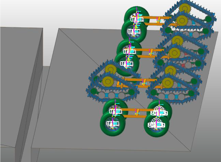
The frame model was created in UG software and imported into RecurDyn. Then, two models of coordinated variable triangular track under the stretch and contraction state were created by using the track toolbox in RecurDyn, and they are constrained on the rear axles of the frames, respectively. The front tire models were created by using tire toolbox and constrained it on the front axles of the frames. The created simulation model is shown in Figure 5.

Schematic of simulation model.
Complete pavement creation in Professional-Body-Ground module. The complex pavement conditions, such as flat land, slope, and trench, were created by using Professional-Body-Ground toolbox. The pavements were set as dry pavement.
Simulating and analysis of straight working on flat pavement
The driving function of driving wheel is: step (time, 0.1, 0, 2, 180 d) (d is the shorthand for degree). The function meaning is that the driving wheel is not driven within 0–0.1 s, the driving angular velocity of driving wheel is from 0 d/s to 180 d/s within 0.1–2 s and the driving angular velocity of driving wheel is 180 d/s after 2 s. The walking mechanism fall on the ground freely within 0–0.1 s, moved forward with uniform acceleration within 0.1–2 s and moved at a uniform speed after 2 s.
In order to compare the velocity characteristics of the coordinated variable triangle track in the two states of stretch and contraction state, the velocity–time curves of the walking straight were exported, as shown in Figure 6.

The velocity–time curves of the walking straight.
The blue curve is velocity–time curve of the walking mechanism in the stretch state, and the green curve is velocity–time curve of the walking mechanism in the contraction state. It can be seen that the walking mechanism is in acceleration state in the first 2 s, and there is no significant difference in acceleration performance between the two states, both of which are about 2.5 m/s2. The velocity of walking mechanism fluctuates steadily at 0.45 m/s in the stretch state after 2 s and fluctuates steadily at 0.5 m/s in the contraction state. Thus, the walking mechanism has higher walking speed and better mobility in the contraction state under the same driving angle velocity. The main reason may be that the coordinated variable triangle track has a larger grounding area and brings about a larger friction resistance in the stretch state, which leads to a lower speed of the walking mechanism.
In order to compare the stability of the walking mechanism in the stretch and contraction states, the amplitude of vibration angular velocity of the walking mechanism in the straight walking was exported, as shown in Figure 7. The amplitude of vibration angular velocity can reflect the stability of the walking mechanism during walking to a certain extent.
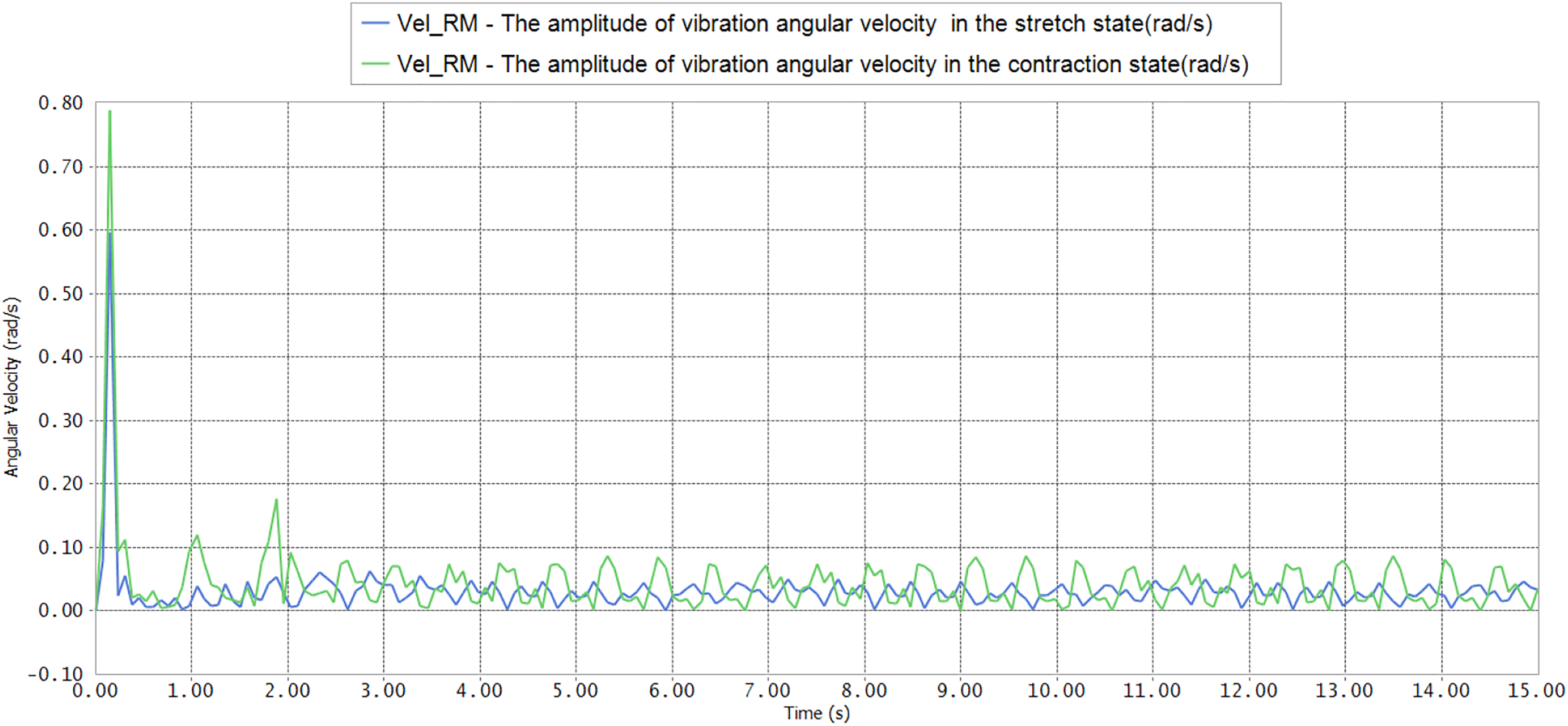
The amplitude of vibration angular velocity of walking mechanisms.
The blue curve is the amplitude of vibration angular velocity of the walking mechanism in the stretch state, and the green curve is the amplitude of vibration angular velocity amplitude curve of the walking mechanism in the contraction state. Obviously, when the walking mechanism starts, the amplitude of vibration angular velocity is larger. After 2 s of speed stabilization, the average vibration angle is 3.1 rad/s in the stretch state and t the average vibration angle is 4.4 rad/s in the contraction state. The stability of the wheel-track walking mechanism in the stretch state is better than that in the contraction state obviously. The reason for this phenomenon is that the ground area of the coordinative variable triangle track in the stretch state is larger and the mass center of the track moves down at the same time. These two reasons lead to the better stability of the walking mechanism in the contraction state.
The driving torque–time curves were exported, as shown in Figure 8. 25 The blue curve is the driving torque–time curve in the stretch state, and the green curve is the driving torque–time curve in the contraction state. By comparison, the fluctuation range of green curve is obviously larger than that of blue curve after 2 s. The driving torque is stabilized after 3 s, the peak value of the driving torque pulse in the contraction is about 420 N·m and the peak value of the driving torque pulse in the stretch is about 270 N·m. The average torque of the driving torque is 156 N·m in the stretch state and the average torque of the driving torque is 175 N·m in the contraction state. That is to say, when the driving angle velocity is the same, the driving torque in the stretch state is lower than that in the contracted state.

The driving torque–time curves of driving wheels.
Generally, the velocity of the walking mechanism in the stretch state is lower than that in the contraction state by given the same driving speed. But the stability of the walking mechanism and the driving torque in the contraction state are lower than that in the stretch state.
Simulating and analysis of steering working on flat pavement
The steering of the tracked walking mechanism is realized by differential speed between left and right tracked tracks. 26,27 In order to verify the steering performance of the coordinated variable wheel-track walking mechanism, the drive function of the left driving wheel was given: step (time, 0.1, 0, 2, 180 d); the drive function of the right driving wheel was given: step (time, 0.1, 0, 2, 120 d). The function meaning is that the driving wheels are not driven within 0–0.1 s, the walking mechanisms fall on the ground freely; the driving angle velocity of the left driving wheel is from 0 d/s to 180 d/s within 0.1–2 s and the driving angle velocity of the right driving wheel is from 0 d/s to 120 d/s within 0.1–2 s; the driving angle velocity of the left driving wheel is 180 d/s and the driving angle velocity of the right driving wheel is 120 d/s after 2 s.
In order to compare the steering efficiency of the coordinated variable wheel-track walking mechanism in the stretch state and the contraction state, the direction angle curves of the walking mechanisms were exported, as shown in Figure 9.
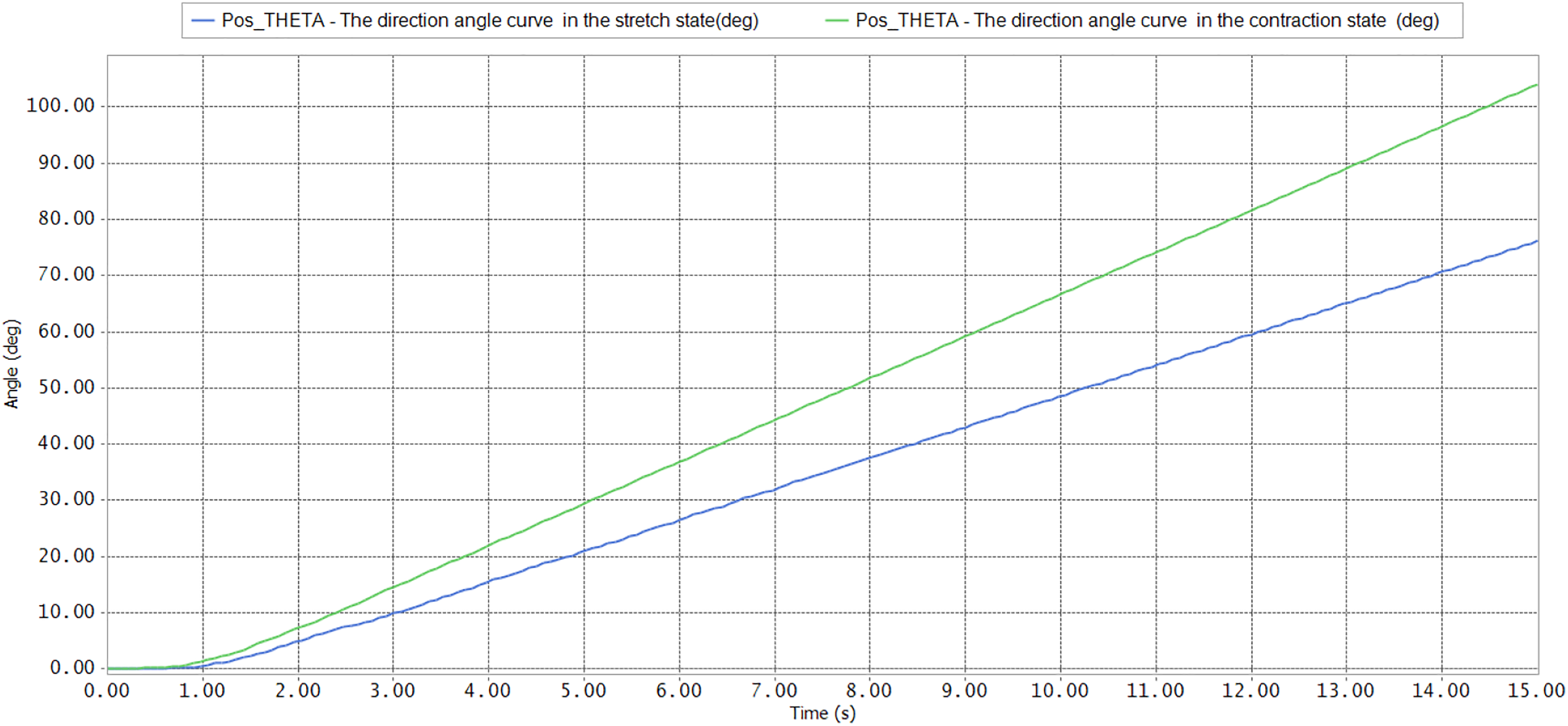
The direction angle curves of the walking mechanisms.
The blue curve is the direction angle curve of the walking mechanism in the stretch state and the green curve is the direction angle curve of the walking mechanism in the contraction state. In 15 s, the steering angle of the walking mechanism increases by about 77° in the stretch state and increases by about 104° in the contraction state. Obviously, the change rate of the direction angle of the walking mechanism in the contraction state is higher than that in the stretch state. It can be concluded that the steering efficiency of the walking mechanism in the contraction state is higher than that of the walking mechanism in the stretch state. In some curves with higher curvature, turning can be carried out in the contraction state. The reason for this phenomenon is that the ground area of the coordinative variable triangle track in the contraction state is smaller, which results in a smaller steering resistance of the ground to the track in the contracted state, which is also consistent with our original intention.
The last section summarizes the kinematics rules that the steering angles of front tires should conform to during the motion of the wheel-track walking mechanism. The front tires should be in the pure rolling state and the lateral force is 0 N during steering when the steering angles of the front tires satisfy the equations (22) and (23). However, the steering angle is difficult to satisfy the equations (22) and (23) due to the difficulty of measuring the slip of the tracks accurately during walking and the limitation of the steering mechanism. Therefore, the front tires will inevitably be subjected to lateral force during steering. In order to compare the lateral force of the front tires of the walking mechanism in the stretch and contraction states, the steering angles of the front tires were not given in the simulation, so as to compare the impact of differential steering on the front tires.
The tires lateral force curves were exported, as shown in Figure 10. The blue curve and the green curve are the lateral forces on the left tire and the right tire in the stretch state, respectively. The red curve and the yellow curve are the lateral forces on the left tire and the right tire in the contraction state, respectively. The simulation results show that the average lateral force of the left tire in the stretch state is 293 N, the average lateral force of the right tire in the stretch state is 687 N, the average lateral force of the left tire in the contraction state is 97 N, and the average lateral force of the right tire in the contraction state is 79 N. Obviously, when the tires are steering, the lateral force on the tires in the contraction state is less than the lateral force on the tires in the stretch state. Generally, when the steering is in a contraction state, the lateral force of the tire is smaller. It is conducive to prolonging the service life of the tires.
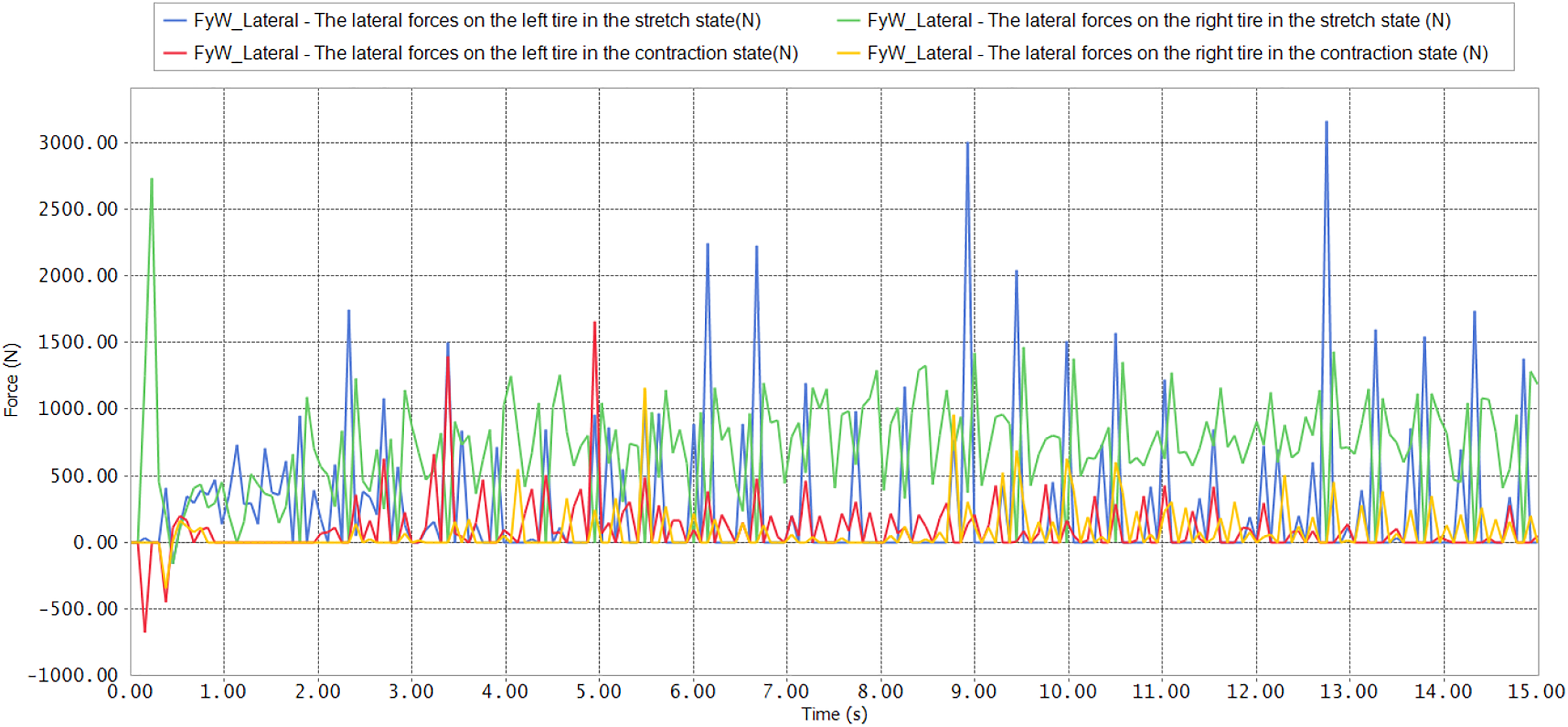
The lateral force curves of the front tires.
The driving torque–time curves were exported, as shown in Figure 11. 25 For the convenience of comparison, only the driving torque–time curves of the left tracks in two states were compared.

The driving torque–time curves of driving wheels.
The blue curve is the driving torque–time curve in the stretch state and the green curve is the driving torque–time curve in the contraction state. As can be seen from Figure 11, the driving torque in the contraction state is less than that in the stretch state obviously. The driving torque is stabilized after 3 s, the peak value of the driving torque pulse in the contraction is about 600 N·m and the peak value of the driving torque pulse in the stretch is about 350 N·m. The simulation results show that the average value of the driving torque in the contraction state is 207 N·m, while the average value of the driving torque in the stretch state is 400 N·m. When the walking mechanism is in contraction state, the grounding area of the track is smaller, which results in smaller driving torque and better steering performance.
Simulating and analysis of climbing slope
In order to verify the climbing performance of the wheel-track walking mechanism, the climbing performance of the wheel-track walking mechanism, the tracked walking mechanism, and the wheeled walking mechanism were compared. 28 As shown in Fig. 12, the schematic view of climbing for these types of walking mechanisms. The climbing simulation analysis was carried out on the 20° slope and the 30° slope. The velocity of driving wheels of the wheel-track walking mechanism and the tracked walking mechanism is 180 d/s. Considering the radius ratio of tire and the driving wheel, the velocity of rear driving wheel of wheeled walking mechanism is 78.8 d/s. By comparing the two climbing conditions, it is found that the wheel-track walking mechanism in the stretch state and the tracked mechanism can climb over the 30° slope, and the climbing performance of the tracked mechanism is better than that of the wheel-track walking mechanism in the stretch state. At the slope of 20°, the wheel-track walking mechanism in both states and the wheel-track walking mechanism can pass through the slope, but the wheeled walking mechanism cannot pass through the slope. In general, the climbing performance of the wheel-track walking mechanism is significantly better than that of the wheeled walking mechanism. And the climbing performance of the wheel-track walking mechanism in the stretch state is slightly better than that in the contraction state.
Schematic of climbing for the four types of walking mechanisms.
The climbing velocity curves of these walking mechanisms of climbing 20° slope were exported, as shown in Figure 13.

The climbing velocity curves of these walking mechanisms of climbing 20° slope.
The blue curve is the climbing velocity curve of the wheel-track walking mechanism in the stretch state, the green curve is the climbing velocity curve of the wheel-track walking mechanism in the contraction state, the red curve is the climbing velocity curve of the tracked walking mechanism, and the yellow curve is the climbing velocity curve of the wheeled walking mechanism. The simulation results show that the average climbing velocity of the wheel-track walking mechanism in the stretch state is 3.9 m/s, that of the wheel-track walking mechanism in the contraction state is 3.7 m/s, that of the tracked walking mechanism is 3.8 m/s, and that of the wheeled walking mechanism is −4.6 m/s. From the analysis of the results, the climbing velocity of the wheel-track walking mechanism in stretch state is slightly better than that of the tracked walking mechanism; the climbing velocity of the tracked walking mechanism is slightly better than that of the wheel-track walking mechanism in the contraction state; and the climbing velocity of the wheeled walking mechanism is negative because it is in the downslide state during the climbing, so it cannot climb the slope. Obviously, the climbing ability of the wheel-track walking mechanism is qualitatively changed compared to the wheeled walking mechanism, but there is not a significant gap compared with the tracked walking mechanism (even the wheel-track walking mechanism has the better climbing ability in the stretch state than the tracked walking mechanism). Therefore, the wheel-track walking mechanism improves the climbing ability while retaining the mobility as much as possible.
Simulating and analysis of passing trench
As shown in Figure 14, the schematic view of passing trench for these types of walking mechanisms. The width of trench was set to 500 mm. The simulation results show that the tracked walking mechanism and the wheel-track walking mechanism can pass the trench smoothly, but the wheeled walking mechanism cannot pass the trench. It can be seen that the passing trench performance of wheel-track walking mechanism is also improved to a certain extent compared with the wheeled walking mechanism.
Schematic of passing trench for the four types of walking mechanisms.
The body heights of several walking mechanisms during passing trench were exported. As shown in Figure 15, the change of body height can reflect the stability of the walking mechanism during passing trench. 23,29

The body heights of several walking mechanisms during passing trench.
The blue curve is the body height change curve of the wheel-track mechanism in the stretch state, the green curve is the body height change curve of the wheel-track mechanism in the contraction state, and the red curve is the body height change curve of the tracked mechanism. The stability of passing trench of the wheeled mechanism was not discussed here because the wheeled walking mechanism cannot pass 500 mm trench. About 4.5 s, the height of the body of the wheel-track walking mechanism decreases, which is caused by the front wheel tires sagging when the walking mechanism passes the trench. But the height of the body of the tracked walking mechanism changes smoothly at 4.5 s. About 8.5 s, the track of the walking mechanism began to pass the trench, and the body of the three walking mechanisms suddenly rose. The wheel-track mechanism in the contraction state rose sharply and lasted a long time, followed by the wheel-track mechanism in the stretch state, and the tracked walking mechanism was most smooth.
In summary, the stability of passing trench of the tracked walking mechanism is better than that of the wheel-track walking mechanism, and the stability of passing trench of the wheel-track walking mechanism in the stretch state is better than that in the contraction state.
Conclusion
In this article, a coordinated variable wheel-track walking mechanism was designed. Unlike the general wheel-track walking mechanism, the track of the coordinated variable wheel-track walking mechanism adopts a coordinated and variable triangular track. The landing area of the coordinated and variable triangular tracks can be changed. Different states of the coordinated variable triangular tracks are selected according to different road conditions and load conditions. In order to solve the relationship between the steering angle of wheels and the speed of tracks in the steering process of the wheel-track walking mechanism, the kinematics equation of the wheel-track walking mechanism was established, and the steering angle equation of the front tires was derived. Based on RecurDyn software, the simulation analysis of the coordinated variable wheel-track walking mechanism under different working conditions was carried out. Several conclusions can be drawn from the motion simulation: The motility of the coordinated variable wheel-track walking mechanism in the stretch state is better than that in the contraction state. The stability of the coordinated variable wheel-track walking mechanism in the stretch state is better than that in the contraction state. The driving torque of the driving wheel is higher in the contraction condition with same driving angular velocity. The wheel-track walking mechanism solves the problem of low climbing ability of the wheeled walking mechanism. Even on a 20° slope, its climbing ability is better than that of the tracked walking mechanism, because the mass of the wheel-track walking mechanism is less than that of the tracked walking mechanism and the sliding force is less. The wheel-track walking mechanism can pass trenches which the wheeled walking mechanism cannot, but the stability of passing trenches is lower than that of the tracked walking mechanism.
Footnotes
Author’s note
Liguo Zang is also affiliated with College of Engineering, Nanjing Agricultural University, Nanjing, Jiangsu, People’s Republic of China.
Declaration of conflicting interests
The author(s) declared no potential conflicts of interest with respect to the research, authorship, and/or publication of this article.
Funding
The author(s) disclosed receipt of the following financial support for the research, authorship, and/or publication of this article: This work was supported by the National Natural Science Foundation of China (grant number. 1605215), the China Postdoctoral Science Foundations (grant number. 2018M630593,2019T120450), Research Foundation of Nanjing Institute of Technology(grant number. CKJA201906), and Qing Lan Project.