
Abstract
In this work, geometry-based finger kinematic models for joint rotation configuration are proposed. The purpose of the work is to provide an effective means of describing an individual-specific finger motion during flexion or extension movements as precisely as possible. Based on the finger’s geometric postures that are observed when fingers naturally grasp a cylindrical object with a circular cross-section, its geometric relation between each phalanx of a finger and the object is extracted, and forms of contact between them are taken into consideration to secure more degrees of freedom for representing finger motions and are parameterized in the model development. A parameter identification approach is adopted to find model parameters that can be used to describe an individual-specific grasping style. For the validation of the proposed models, a set of optical motion capture experiments is performed. From the simulation study, one can see that the models provide one of the feasible and viable solutions to imitate the human finger’s flexion and/or extension movements.
Keywords
Introduction
The motion of the hand that implements object manipulation or grasp (prehension) is based on the function of fingers. Understanding the actuations of flexion or extension motions of fingers is required to replicate and implement those movements in various fields. Thus, finger kinematic models have widely been studied in a variety of research/industrial sectors, such as for human fingers simulation, 1 finger motion coordination, 2 –4 virtual hand modeling and simulation, 5 –9 articulated human hand, 10,11 prosthetics, 12 for example. The finger models need to have the ability to express a naturalistic finger posture depending on the degree of flexion of the finger. Since the finger posture is determined solely on flexion or extension motions, it is required that the models should be able to provide the angular position of each joint as they make a gesture. To cope with these needs, in our recent work, 9 a geometry-based finger kinematic model is proposed. It is inspired by a finger posture observed when the hand grasps round-shaped cylinders. Geometric relationships created between the finger and the object are taken into account. Based on the relationships, the formulas that can calculate joint rotation angles of the finger are derived. In calculating each rotational angle of joints, only one parameter is, namely a radius of a hypothetical circle, involved, in spite that the long finger has three degrees of rotational freedom. This simplicity in configuring the finger posture allows the model to be utilized in robotic finger/hand control systems design for multi-finger coordination. Another work for finger-kinematic model developments was performed by the same authors. 13 In this work, finger postures observed during grasping various cylindrical objects with different cross-sections from the family of conic sections are considered. In addition, four types of contact style are introduced and incorporated in the geometric relations to express various contact styles of the hand during flexion/extension movements. Although the approach is similar to the one used in the previous work, 9 the joint rotation configuration of a finger is numerically obtained since the geometric relations are represented by systems of nonlinear equations. The contribution of the work is to provide a numerical framework for finger kinematic models and to introduce a grasping pattern change scheme using the proposed finger kinematic models. On the basis of recent research, two types of generalized finger kinematic model are proposed in the work by defining two forms of contact. Furthermore, parameterization of their specific features in the geometric point of view is made while sticking to the existing geometric approach. This article is aimed to derive finger kinematic models that are able to describe individual-specific flexion/extension movements by generalizing the contact styles discussed in our previous works. 9,13 To this end, this article is organized as follows. In the second section, geometry-based finger kinematic models that can provide the joint angle configuration of a finger are proposed. Two types of contact conditions are defined. Their geometric features between the phalanges of a finger and the object are used to derive finger kinematic models. This notion is realized in the models by introducing the so-called contact style parameters. In the third section, a parameter estimation scheme is utilized to find an optimal contact style parameters with which individual-specific finger movements are best described. Its parameter estimation results are discussed. Finally, the fourth section concludes the article with a summary of the work.
Finger kinematic model for joint angle calculation
An overview and modeling scheme
Finger kinematic models in the work are intended to provide a joint rotation configuration for the finger posture during flexion or extension of the human hand (See Figure 1). The contribution of the present work, compared to our previous works, is to generalize the “forms of contact” between the phalanges of a finger and the object for providing an effective means of describing an individual-specific finger motion. Two types of contact location are assumed: During flexion or extension, the object is held firm on (1) the grooves of finger joints (see Figure 2) and (2) the flesh that lies between two joints (see Figure 3). In the figures, schematics of an index finger simulating the finger posture and surrounding geometry in different forms of contact are given. The forms of contact are interpreted as the way in which phalanges interact with the object during flexion/extension motions.

Finger posture in the geometric viewpoint. Notes: The dotted lines represent proximal, middle, and distal phalanges, respectively. The origin is on the MCP joint.

Schematic of finger posture for type I model. (a) Photograph of finger posture and (b) its schematic representing the forms of contact adopted.

Schematic of finger posture for type II model. (a) Photograph of finger posture and (b) its schematic representing the forms of contact adopted.
To endow the models with the capability to describe contact styles, the parameter set
The finger kinematic models proposed in the work can be construed as a generalized version of the previous models, which are capable of providing more degrees of freedom (DOFs) to precisely describe finger’s flexion/extension motions for an individual-specific grasping style. The ideas from our previous works are compared with the proposed models and their comparative features are listed in Table 1. In the following sections, two finger kinematic models with different forms of contact are proposed and discussed.
Comparison of geometry-based kinematic models for joint rotation configuration of a finger.a
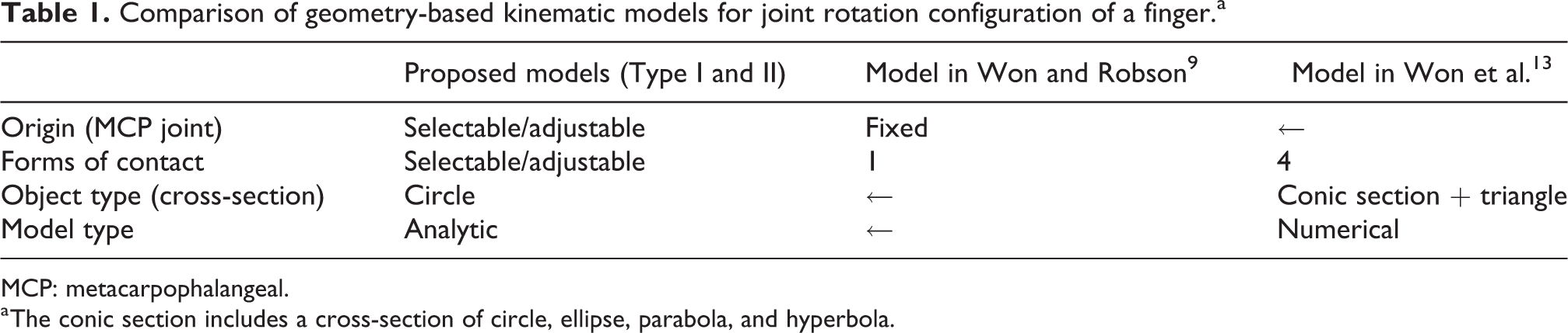
MCP: metacarpophalangeal.
a The conic section includes a cross-section of circle, ellipse, parabola, and hyperbola.
Basic assumptions
Human long fingers (index, middle, ring, and pinky fingers) have three joints: MCP joint, proximal interphalangeal (PIP) joint, and distal interphalangeal (DIP) joint. Each finger has four DOF (flexion/extension in DIP, flexion/extension in PIP, and flexion/extension and abduction/adduction in MCP joint). 14 For simplicity in the present work, it is assumed that only flexion/extension motion in the MCP joint is considered, which leads to a finger model with three degrees of rotational freedom motion.
Geometry-based modeling: Type I
Figure 2 depicts a schematic for the finger kinematic model which hereafter is named type I. It is assumed in the model that during flexion/extension motions each contact takes place at a point on the line segment which is in parallel to the groove in-between adjacent phalanges and its length is the same as the thickness of the joint (denoted by dotted circles in the figure). As mentioned earlier, this assumption can be materialized by introducing contact angles. q 1 represents the angle between the proximal phalanx and the virtual line where the grove in-between the proximal and middle phalanges forms, and q 2 respectably. q 3 is the angle between the distal phalanx and a virtual groove assumed to be attached to the fingertip, which is used to determine the angle of the DIP joint.
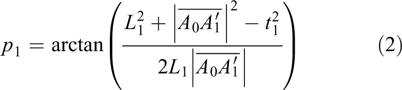
Based on the geometry of a finger in Figure 2(b), the rotational angles in the finger joint configuration can be obtained by trigonometric angle formulas (e.g. law of cosine). Before proceeding, let us define the bias angle

where Ox and Oy are the coordinates of the MCP joint of the finger under consideration.
For the triangle
where
For the triangle

where
The rotational angle

For the triangle

where
Similarly, for the triangle

where
For the triangle

where
The rotational angle

For the triangle

where
Finally, for the triangle
where
For the triangle

where
The rotational angle

From the joint angles for each R, the trajectory of fingertip

Geometry-based modeling: Type II
Figure 3 shows a schematic of finger posture for type II model proposed in the work. Type II model is designed so that each contact point is on the line perpendicular to the corresponding phalanx and its distance between the contact point and its phalanx is taken as the thickness of the neighboring joint. Similarly, contact angles are introduced to reflect the geometric configuration.
Based on the contact configuration defined in Figure 3(b), type II model is derived. For the triangle
where
For the triangle

where
The rotational angle

For the use in the calculation of the PIP joint angle, the following quantities are calculated in advance for the triangle

where
Similarly, for the triangle
where
For the triangle

where
The rotational angle

For the use in the calculation of the DIP joint angle, the following quantities are calculated in advance for the triangle
where
Finally, for the triangle

where
For the triangle
where
The rotational angle

Small discussion
The joint angles in each model are confined to a working range of
Type I (represented by the set of equations (4), (8), and (12)) and type II (by the set of equations (16), (20), and (22)) models represent one-DOF joint rotation configuration of the human fingers, respectively. Given the anthropometric dimensions of a finger and the contact style parameters, the joint rotation configuration of a finger can be simply determined by a single control parameter R. By providing different values of R with respect to time, flexion/extension of a finger can easily be derived. Furthermore, it is worth to note that the given models have no constraints on the angles between joints (i.e. not coupled) and each joint angle is independently determined by just a single parameter.
Thanks to these features, it is thought that these models can describe inter-joint coordination and interfinger coordination functions of the human hand 2,10,15,16 and can also be applied in various fields, such as grasp algorithm development 17,18 and robotic hand control systems design. 19 –21
Validation of finger kinematic models
The capability of the proposed models to represent a naturalistic behavior of the human fingers during flexion/extension movements is investigated. To do this, a set of optical motion capture experiments has been conducted. Optical markers were attached on the index finger of a subject where the joints are and the movement of the finger was recorded as shown in Figure 4. The subject was ordered to make several consecutive flexion and extension motions to acquire data with more intrinsic features of finger motion for the subject. From the motion capture data, joint angles of the finger were extracted and the fingertip trajectory was calculated using equation (13). To see how much the proposed models are able to represent a finger motion of the subject, the fingertip trajectory in the Cartesian space from each model and the captured data for the subject were compared. For the comparison purpose, contact style parameters are arbitrarily selected for the models each in consideration of physical appearance of the index finger of the subject participated in experiments (see Table 2). Comparison results are shown in Figure 5. From the figures, one can see that the models show the availability to replicate finger motions with a high degree of agreement except in a full flexion region. Disagreement in this region leads us to utilize parameter estimation methods. In the following section, the parameter estimation of contact style parameters in each model is described.

Photograph of the motion capture validation process.
Contact style parameters for model validation.


Experimental versus model results for: (a) type I and (b) type II models.
Contact style parameter estimation
Problem formulation
In this section, contact style parameters that can accurately represent a subject’s finger motion are obtained through parameter estimation methods.
The problem of parameter estimation for the proposed finger kinematic models is formulated as a least square optimization problem

where

where
Parameter estimation results
The optimal parameters ξ* after least square optimizations are listed in Table 3 and their results are shown in Figure 6. Through the process of parameter estimation, the characteristic features of the proposed models can be described as follows: Although parameter estimation results may vary depending on the choice of search bounds, individual-specific parameters for representing finger motions of subjects can be obtained through parameter estimation processes. The contact angle q
3 of type I model is the one indicating the direction of the virtual groove attached to the fingertip, which has no physical meaning and only is used to calculate the angle of the DIP joint. The simulation results show that the optimal q
3 follows the lower value of the search bounds, and the other two values of q
1 and q
2 are not significantly affected by the change in the value of q
3 during the parameter estimation processes. It is noted that q
3 can be used to fine tune the trajectory of the fingertip in a full flexion region. In reality, the direction of the actual finger groove varies during flexion/extension: However, since contact style parameters from the parameter estimation process are fixed, type I model seems somewhat lacking in describing the overall trajectory of the fingertip (in a full flexion region, especially). On the other hand, the points of contact when a finger wraps an object are observed to be little varied. Thus, it is likely that type II model with fixed parameters reflects best the characteristics of finger movements.
Optimal parameters for the models.a

a lb and ub are the lower and upper values of search bounds.

Experimental versus model results for: (a) type I and (b) type II models. Note: Contact style parameters are obtained through parameter estimation.
Conclusion
In the work, geometry-based finger kinematic models that can be utilized to describe flexion/extension movements of a finger are proposed. Based on a finger posture observed when the hand grasps a cylindrical object, the geometric relationship created between the fingers and the object is modeled. Two types of forms of contact are assumed. The so-called contact style parameters are introduced to give more DOFs in describing individual-specific finger movements. Following the assumptions made, two types of model are derived and their capabilities to simulate finger motions are evaluated with measurements from optical motion capture experiments. Furthermore, a parameter estimation scheme is employed to find an individual-specific set of contact style parameters. From the comparison of models and experimental results, one can see that the proposed models have a capability to represent individual-specific finger movements of the hand. Furthermore, it is highly likely that the models have possible areas of application to the robotic/artificial hands design.
Footnotes
Declaration of conflicting interests
The author(s) declared no potential conflicts of interest with respect to the research, authorship, and/or publication of this article.
Funding
The author(s) received no financial support for the research, authorship, and/or publication of this article.