
Abstract
When autonomous underwater vehicle following the wall, a common problem is interference between sonars equipped in the autonomous underwater vehicle. A novel work mode with weighted polling (which can be also called “weighted round robin mode”) which can independently identify the environment, dynamically establish the environmental model, and switch the operating frequency of the sonar is proposed in this article. The dynamic weighted polling mode solves the problem of sonar interference. By dynamically switching the operating frequency of the sonar, the efficiency of following the wall is improved. Through the interpolation algorithm based on velocity interpolation, the data of different frequency ranging sonar are time registered to solve the asynchronous problem of multi-sonar and the system outputs according to the frequency of high-frequency sonar. With the reinforcement learning algorithm, autonomous underwater vehicle can follow the wall at a certain distance according to the distance obtained from the polling mode. At last, the tank test verified the effectiveness of the algorithm.
Keywords
Introduction
Nowadays, water conveyance tunnels have been an important transportation route in hydraulic engineering. 1 When detecting the wall crack in the water conveyance tunnels, the ability of following the wall at a certain distance is the basic premise of autonomous underwater vehicle’s (AUV’s) safe operation. 2 Ranging sonar is widely used in obtaining the distance of obstacles, its principle is the transducer actively emits acoustic waves and obtains the distance information of obstacle by receiving the echo reflected by the obstacle. 3 Efficient access to stable and accurate distance data is an important performance index of the ranging sonar.
The water conveyance tunnel inspection AUV (AUV-T; Figure 1) in this study is equipped with eight ranging sonars. The ranging sonars are mounted on the top, bottom, left, and right positions of the bow and stern to measure the distance of the AUV from the surrounding walls. The model of the sonars is DYW-50/200-NB with a range of 0.6–120 m at 200 KHz. Their half power angle is 7.5°. If the channel width is less than 0.6 m, the stability and accuracy of the sonars will decrease rapidly due to the interference caused by the echo.
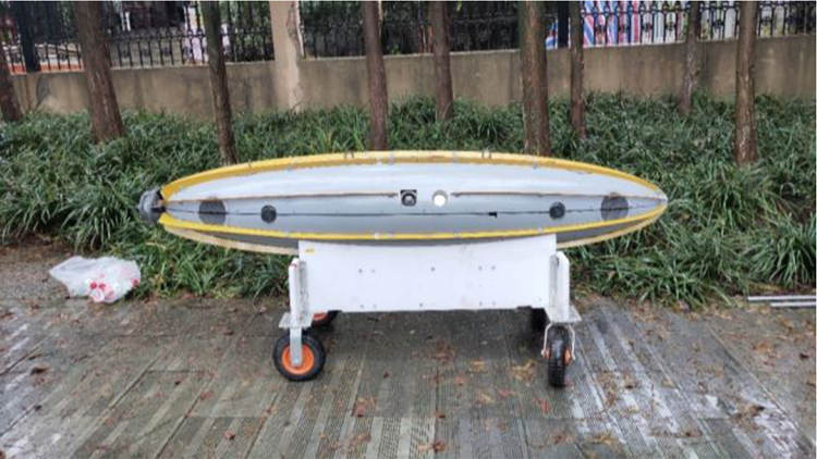
“AUV-T” equipped with eight sonars. AUV-T: tunnel inspection autonomous underwater vehicle.
Usually, the working mode of the ranging sonar is that a plurality of sonars emit acoustic waves simultaneously at a fixed frequency and acquire obstacle information, 4 but there will be interference in the sonar information in different directions. Experiments show that the stability and accuracy of the ranging sonar data will decrease rapidly with the decrease of the channel width after the channel width is lower than a certain threshold, and even the data become erroneous. Although the use of polling mode of the ranging sonar can avoid the interference between the sonar, but the frequency of access to data will be greatly reduced, thus reducing the AUV obstacle avoidance efficiency. By reducing the polling interval, the efficiency can be improved, but when the channel is narrow, shortening the polling interval can cause mutual interference between the sonar and cannot obtain accurate data.
On the other hand, the different sampling frequencies of the different sensors output by the dynamic weighted polling mode (DWPM) will cause asynchronous problems. From the engineering point of view, the existing time registration methods, such as least squares, extrapolation, maximum entropy, and so on, have some limitations and one-sidedness. These methods use the sampling frequency of the low-frequency sensor as the standard, reduce the utilization rate of the measured data, and reduce the accuracy of the system, so that the weighted polling mode proposed in this article has lost its meaning.
Recently, there have been many researches on the application of sonar interference and reinforcement learning in AUV. Ohya et al. constructed two ultrasonic ranging systems to investigate the influence of characteristics of the sensing system. 5 The characteristics of the system differ from each other. Li et al. proposed the ultrasonic ranging method using discrete chaotic phase modulated signal. 6 The chaotic phase modulated signal showed the property of sharp autocorrelation and flat cross-correlation. Kleeman presented the sonar system which can produce accurate measurement and on-the-fly single cycle classification of planes, corners, and edges. 3 This article showed how to use double pulse coding of transmitted pulses to simultaneously suppress interference and classify. Kleeman proposed the approach to rejecting interference between sonar systems which was based on identifying a transmitter by sending a double pulse with known separation. 7 The ability was demonstrated by the experiment. Browne and Kleeman proposed the sonar ring refreshing at 60 Hz for 5.7-m range. 4 It can result in lower latency and denser measurements. Huang et al. designed the environment states and obstacles avoidance behaviors, 8 then the reinforcement learning was used to select the state–action combinations. Simulation results showed that AUV can meet the requirements of safe navigation. Liu et al. adopted the reinforcement learning to control AUV, 9 Q-learning, back-propagation neural net, and artificial potential were integrated to implement avoidance planning for AUV. The simulation test verified the validity and feasibility of the motion planning.
It can be seen that the current research on sonar is mostly limited to the improvement of sonar performance, and it is difficult to solve the problem of mutual interference between sonar due to narrow channel, while the application of sonar information in AUV is limited to obstacle avoidance research, and there is basically no relevant research on wall following. Combining with the current sonar working mode and the shortcomings of the above existing situation, a DWPM for multi-sonar AUV is proposed in this article. In this mode, the ranging sonar works in a DWPM, the system can independently identify the environment complex situation, dynamically establish the environment model and switch the working frequency of the sonar. Through the polling mode, the interference between the sonar can be avoided, the data accuracy of the loudness can be improved. The system establishes the corresponding dynamic weighted frequency equation according to the velocity component and the obstacle distance in each sonar direction, and dynamically adjusts the working frequency of the sonar to ensure that the sonar adaptively improves or reduces the working frequency according to the environment variable in the current direction. When the speed is faster or the obstacle is closer, the obstacle distance information in the current direction can be quickly acquired. Through the interpolation algorithm based on velocity interpolation, the data of different frequency ranging sonar are time registered to solve the asynchronous problem of multi-ranging sonar, and the system is based on the frequency of the high-frequency sonar to output the obstacle distance. This approach avoids the asynchronous problem due to the noncoincidence of the multi-sonar sampling frequency and can perform efficient data output. When following the wall, the distance between AUV and wall obtained according to polling mode is taken as the input of reinforcement learning algorithm. According to the output action command, AUV performs the corresponding yaw movement, so as to realize the wall following.
The rest of the article is organized as follows. The multi-sonar DWPM steps are presented in the second section. In the third section, the data fusion and time registration algorithm are proposed. The application of reinforcement learning in AUV wall following is shown in the fourth section. Then the results of the experiments are given in the fifth section, and quantitative analysis is performed later. Finally, the sixth section concludes and summarizes the article.
Dynamic weighted polling mode
The multi-sonar weighted polling mode steps presented in this article are shown in Figure 2.

Weighted polling mode.
Static safe distance
The static safety distance means the positioning error area in the sonar mounting direction. 10 Usually, the positioning error area of AUV is an ellipse. As shown in Figure 3, the parameters of ellipse include the standard deviation, variance, spreading factor, and AUV heading angle of the ranging sonar. Here is the equation


Safety alert distance. (a)
In the equation,
Safety alert distance
The alert distance threshold equation consists of the static part and the velocity part. Here is it

In the equation, hi stands for the security alert distance threshold of AUV in the direction of i (including the bow, stern, port, starboard, same as below), d stands for the static safe distance, ai stands for the static distance correction factor, vi stands for the velocity, and bi stands for the speed–distance correction factor.
Dynamic sonar sampling frequency
The safety distance triggering factor in the dynamic sonar sampling frequency equation is determined by the relationship between the obstacle distance detected by the sonar and the safety alert distance. Here is the equation

In the equation, fi stands for the sonar sampling frequency in the direction of i, f 0 stands for the basic sampling frequency of the sonar, h stands for the safe distance trigger factor, vi stands for the velocity, mi stands for the speed–frequency correction factor, si stands for the obstacle distance detected by the sonar, ni stands for the distance–frequency correction factor, and g(x) is the external interface function.
When the safety alert distance threshold is not reached, the AUV will poll at the basic sampling frequency. At this time, the obstacle information will not trigger the local obstacle avoidance plan. When the safety alert distance threshold is reached, the mode of sampling frequency will be triggered. The system will take different sampling frequencies for the sonar in different directions depending on the speed in different directions and the distance of the obstacle. In addition, the equation sets the unified external interface function g(x) for the sampling frequency adjustment under complex conditions. If the voltage is low, the sampling frequency of all the sonar can be reduced by the external interface function to reduce the energy consumption. g(x) is set to 1 when no external interface function is required. Through the interface function, the system can refer to the AUV state and the sea condition information to realize the quadratic precision adjustment of the sampling frequency of the sonar.
Data fusion and time registration
There are three cases of weighted polling mode as shown in Figure 4.

Data fusion and time registration.
Mode 1
When the distance in all directions is greater than the safety alert distance, the sonar will be polled according to the basic sampling frequency fa . At this time the poll mode taken is the bow and the port sonars launch sound waves firstly, after the interval time ta , the stern and the starboard sonars launch sound waves.
Mode 2
When the sonar in some or all directions takes the dynamic sampling frequency so that the sampling frequency of the sonar in each direction is the same (the sampling frequency is fb ), the sonar will work in the polling mode. At this time the poll mode taken is the bow and the port sonars to launch sound waves firstly, after the interval time tb (tb < ta ), the stern and the starboard sonars launch sound waves.
Mode 3
When the sonars in some or all directions take the dynamic sampling frequency and the sonar sampling frequencies in the respective directions are not exactly the same, the sonars will sample at the respective frequencies. In order to avoid the interference of the sonar in the relative direction, the following algorithm is used.
Assuming that the two sonars in the relative direction are 1 and 2, respectively, the real-time sampling frequency is

The smaller real-time sampling interval is
In the above three cases, the asynchronous problem is generated due to the sampling frequency of the sonar, and the time registration is performed by the fusion algorithm based on velocity interpolation. Normally, the AUV is slow and the speed will not change suddenly. Therefore, the distance information in the low-frequency signal can be interpolated according to the corresponding speed component and time interval in the direction, so that the system can output the frequency according to the frequency of the high-frequency signal.
Assuming that the frequency of the high-frequency signal is f h, the total time of operation is t h, the frequency of the low-frequency signal is f l, the total time of operation is t l, the component of velocity in its direction is v l, then the output distance based on velocity interpolation is here

In the equation, sl
stands for the obstacle distance obtained by interpolation of low-frequency sensors and
Application of reinforcement learning in AUV wall following
AUV wall following is achieved by adjusting the heading of the AUV when detecting the wall crack in the water conveyance tunnels. AUV sails in tunnels with unknown environmental information, therefore, the desired heading cannot be set in advance. AUV obtains desired heading in real time through reinforcement learning algorithms. The input of the reinforcement learning algorithm is the distance of the AUV from the wall. AUV obtains the accurate distance from the wall according to the DWPM, and output the appropriate desired heading. Combined with reinforcement learning
11
and artificial potential field,
12
reinforcement learning algorithm is used to achieve the optimal control of wall following task. In this article, BP neural network and Q-learning algorithm are combined.
13
–15
The output of each network corresponds to the Q value of an action, that is,

Only on the premise of getting the optimal strategy can the above formula be established. In the learning phase, the error signal is

where

The choice of action is reflected by the value of strengthening function, and the external strengthening value is determined by the potential field method. Firstly, the resultant force of AUV at time t is calculated as follows

As shown in Figure 5, dt
is the distance from AUV to the wall calculated by DWPM at time t, and d
0 is the desired distance, that is, the following distance from AUV to the wall. Then the resultant force of AUV at time


Resultant force of AUV. AUV: autonomous underwater vehicle.
The evaluation function of following distance between AUV and wall is defined as

When
The following behavior of AUV to the wall is divided into nine actions, including turning left with the maximum output, turning left 30°, turning left 20°, turning left 10°, direct flight, turning left 10°, turning left 20°, turning left 30°, and turning right with the maximum output. In the process of wall following, AUV obtains the accurate distance from the wall according to the DWPM and selects the appropriate actions using reinforcement learning algorithm. Through certain control strategies, 16 –18 such as fuzzy dynamic surface control 19 and backstepping sliding mode control, 20 –22 AUV can achieve precise wall following in accordance with control instructions.
Experiment
As shown in Figure 6, in order to verify the effectiveness of the DWPM of sonars proposed, experiments are carried out in the pool. The sonar is fixed on a special customized support along the four directions of up, down, left, and right, and then the bracket is fixed on the x–y carriage. The aerial vehicle can realize the precise motion control in the two-dimensional plane. Therefore, the motion of AUV can be simulated by the x–y carriage.

Pool test of sonar polling mode with x–y carriage.
As shown in Figure 7, the DWPM of sonar is realized by the software written based on Visual C++ 6.0, the working frequency of sonar is controlled by the software, and the data of multiple sonars are obtained.

Sonar data acquisition software.
As the upper sonar is close to the water surface, the upper and lower sonar have slight interference, so the left and right sonar data are taken as an example for analysis. The data obtained from the dock test (about 5 m wide) under static state is shown in Figures 8 and 9. “L” indicates the distance obtained by the left sonars, and “R” indicates the distance obtained by the right sonars.
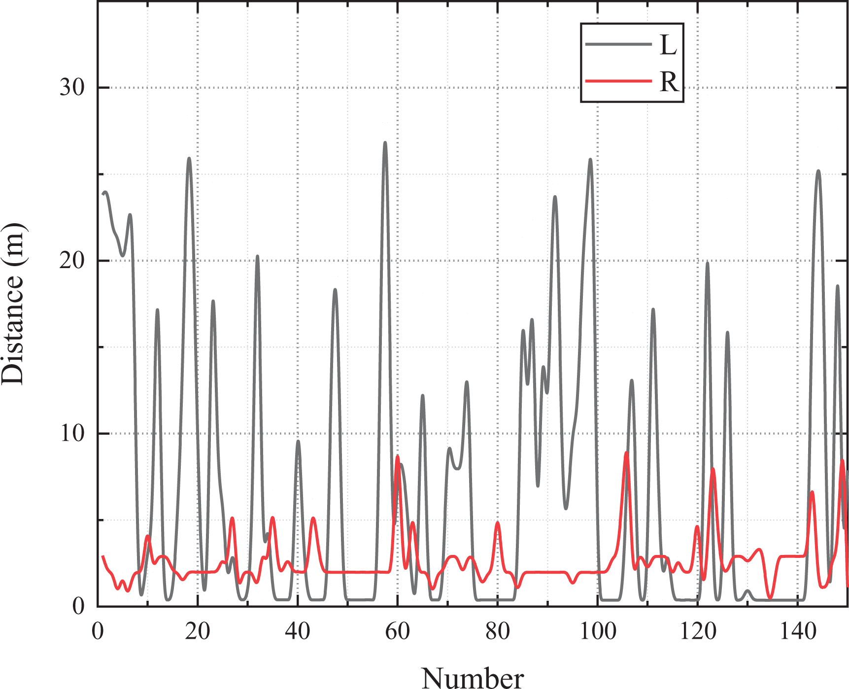
Sonar data in non-polling mode.
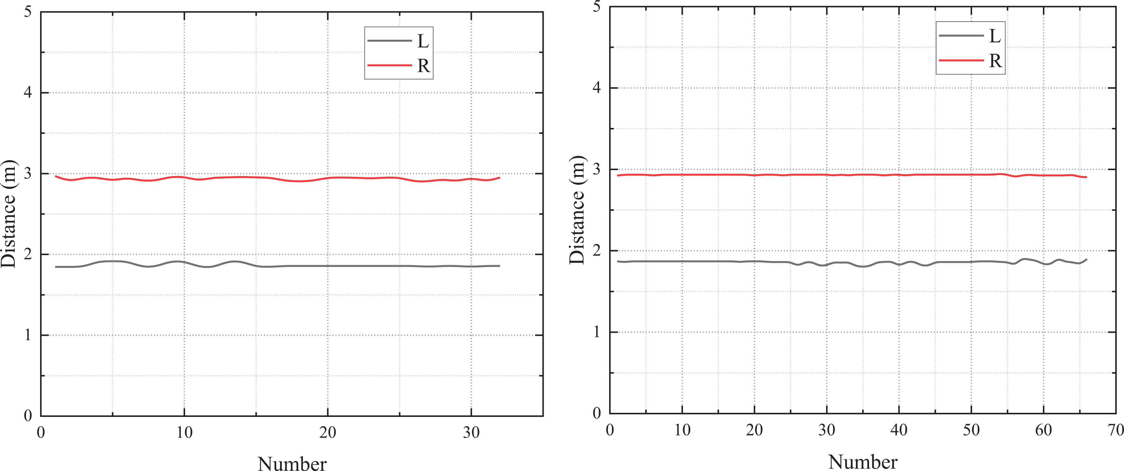
Sonar data in polling mode (conventional polling mode on the left and DWPM on the right). DWPM: dynamic weighted polling mode.
The conventional polling mode refers to the polling work after the same time interval between the left and right sonars. When the polling mode is not used, the interference between the sonars is relatively large. The standard deviation of the left and right sonar is 9.52 and 1.92, respectively.
The standard deviation of the left and right sonar with conventional polling mode is 0.027 and 0.023, respectively, and the standard deviation of the left and right sonar with DWPM is 0.023 and 0.007, respectively. DWPM can obtain more data in the same time under the premise of ensuring the same stability and accuracy as the conventional polling mode.
In the pool (about 30 m wide), the x–y carriage moves in X and Y directions simultaneously (Y direction along the sonar sound direction, X direction perpendicular to the sonar sound direction). The speed in x direction is

Sonar data obtained when the vehicle is moving.
When
As shown in Figure 11, the reinforcement learning algorithm is verified in the pool, and the effectiveness of following the wall is shown in Figure 12.

Verification test in the pool.

Wall following effect in pool test.
It can be seen that AUV can follow the wall stably through the motion instructions obtained by the reinforcement learning algorithm, and the following error is less than 0.5 m. The reinforcement learning algorithm proposed in this article is effective.
Conclusion
Through the multi-sonar weighted polling mode proposed in this article, we can obtain the wall distance information dynamically and efficiently and avoid the mutual interference between the sonar. Through the time registration algorithm based on the speed interpolation, we can avoid the asynchronous problems caused by sensor frequency inconsistency. In the process of wall following, the distance between AUV and wall obtained according to the DWPM is used as the input of reinforcement learning algorithm, and the corresponding yaw motion is executed according to the output action, so as to realize the wall following. Finally, the effectiveness of the algorithm proposed in this article is verified by the pool test.
Footnotes
Declaration of conflicting interests
The author(s) declared no potential conflicts of interest with respect to the research, authorship, and/or publication of this article.
Funding
The author(s) disclosed receipt of the following financial support for the research, authorship, and/or publication of this article: The work was supported in part by the China National Natural Science Foundation (Nos. 51779057, 51709061), and the Equipment Pre-research Project (Project Number 41412030201).