
Abstract
In this article, the hydraulic drive unit that drives the movement of the joint of a legged robot was researched, aiming at improving the control accuracy of the position-based impedance control system with dual input and single output. The state feedback control containing more state information of the system was adopted to replace the traditional output feedback and proportional-integral-derivative (PID) control, through the real-time calculation of the time-varying parameters of the servo valve flow, the nonlinear state space expression of the system was derived, the state feedback matrix and the input transformation amplifier were obtained and the full-dimensional state observer was designed. The experimental results show that the designed full-dimensional state observer can track the state variables of the actual system better. Compared with the traditional output feedback and PID control, state feedback control performs better in aspects of accuracy and system dynamics for the position-based impedance control system, which can further improve the compliance performance of the robot.
Keywords
Introduction
Robots can replace humans to perform heavy, repetitive, dangerous, and other tasks. According to the different tasks to be accomplished, the types of robots are also different. The mobile types of robots include wheeled robots, 1 crawler robots, 2 legged robots, 3 –5 and so on. Hydraulics, 6 –8 pneumatics, 9,10 and motors 11,12 are often used to drive legged robots. The hydraulic-driven legged robot has obvious discontinuous support characteristics. Compared with other motion-type robots, it has better adaptivity for unknown and nonstructural environments. Hydraulic drive mode further enhances the performance of load capacity and motion of the robot. The leg joints of the robot are driven by a highly integrated servo valve-controlled hydraulic drive unit (HDU), which mainly includes a hydraulic cylinder, a small servo valve, a position sensor, and a force sensor. The most representative hydraulic-driven legged robots include BigDog, 13 wildCat, 14 Atlas, 15 HyQ, 16 SCalf, 17 Legged Squad Support System (LS3), 18 and StarlETH. 19
During the movement of the legged robot, the interaction between the foot and the ground will inevitably have rigid collision and impact. The excessive collision force will not only damage the body of the robot and its accompanying electronic equipment but also affect the stability of the robot during the movement. Therefore, the legs of the legged robot should have certain compliance characteristics to reduce the collision force during the interaction of the foot and the ground. Position-based impedance control, where the inner loop adopts position control and the outer loop adopts impedance control, is one of the commonly used methods in active compliance control, and the overall compliance performance is determined mainly by the performance of the control inner loop. As for the legged robot performance requirement, to achieve the desired compliance performance of the impedance control system, the desired stiffness and the desired damping of the outer loop need to be achieved in the system, and the control accuracy of the inner loop of the system position control needs to be maximized. Many domestic and foreign scholars have studied position-based impedance control and applied it to the compliance control of the robot. Won and Kim proposed a disturbance observer (DOB)-based backstepping control that improves the position tracking performance in the presence of both friction and load force in an electrohydraulic system. 20 To reject the dynamic disturbances in some multiple degree-of-freedom manipulators driven by electrohydraulic actuators, Guo et al. proposed state feedback control (SFC) of the cascade electrohydraulic system based on a coupled DOB with backstepping. 21 When position-based impedance control is applied to the HDU, position-based impedance control is more difficult due to the strong inherent nonlinearity of the hydraulic system and time-varying parameters. To improve the position-based impedance control performance of the HDU and to ensure that the leg of the robot has good compliance performance, it is necessary to improve the control performance of the position control inner loop. Although many scholars have performed extensive research work on position systems and put forward corresponding control methods, such as fuzzy control, 22,23 intelligent control, 24 sliding mode control, 25 –27 hierarchical control, 28 and robustness control, 29 for the tracing accuracy, response speed, and disturbance rejection ability of the system. However, these control methods are not practically applied to position-based impedance control of hydraulic-driven legged robots, and the robot has a diversity of given signals, large differences in environmental stiffness, and various loads during actual motion. Whether the control is still effective in the position-based impedance control of HDU remains to be studied further. In the previous research, the analysis researches the serial-parallel composition on dynamic compliances from both position control inner and impedance outer loop. 30 Aiming at the position-based impedance control system of the HDU, the disturbance rejection controller was designed based on the traditional PID controller to improve the control performance of the position inner loop. 31
When the HDU applied in each joint of the robot leg adopts impedance control, it should have high response ability and control accuracy, so that the robot leg can have better compliance to quickly buffer the excessive collision force during the time when the foot of the robot contacts with the ground and to improve the overall stability of robot movement. In this article, HDU was investigated. The control performance of the position-based impedance control system with dual input and single output was studied. The SFC was adopted to replace the traditional output feedback and PID control, aiming at improving the control performance of the system. The research focuses on the following points: First, the nonlinear state space expression of the position-based impedance control system of HDU is derived. Second, the state feedback matrix of the system is solved by the unlimited time output regulator in the optimal control, and the input transformation amplifier is designed for the larger steady-state error of the system. Third, a full-dimensional state observer is designed to observe the state variables of the real system in real time. Fourth, the force sensor is adopted to estimate the time-varying parameters of the servo valve flow in real time. The state feedback matrix, input transformation amplifier, and state observer output error feedback matrix are calculated in real time to complete the SFC of the system. Finally, the tracking ability of the real system state variables by the full-dimensional state observer is verified on the HDU performance test platform, compared with the traditional output feedback and PID control, and the effectiveness and advantages of SFC are verified.
Application of position-based impedance control on the HDU
Introduction of the HDU
The HDU, a kind of highly integrated, valve-controlled and symmetrical cylinder, is an actuator on the leg joint of a robot. The quadruped robot prototype, the single-legged hydraulic drive system, and HDU developed by the author’s unit are shown in Figure 1(a) to (c), respectively.
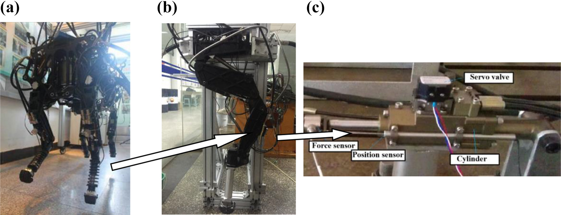
The quadruped robot prototype, single-legged hydraulic drive system and HDU performance test platform. (a) Quadruped robot prototype, (b) single-legged hydraulic drive system, and (c) HDU. HDU: hydraulic drive unit.
Introduction of a position-based impedance control system for the HDU
The active compliance control is adopted to buffer the excessive collision force generated during the movement of the legged robot. When the foot of the robot is in contact with the ground, the sensor detects an excessive impact and causes the leg of the robot to actively retract to alleviate collision and impact. Position-based impedance control is one of the most widely used active compliance control methods, the principle of which is shown in Figure 2.

Position impedance control schematic diagram.
As shown in Figure 2, when the foot end of the robot is not in contact with the ground, that is, there is no load force on HDU (regardless of gravity), the detection value of the force sensor is zero, the impedance position deviation Xe is zero, and the output position XP traces the input position Xr under the action of the control inner loop, and the position control is realized. When the robot foot contacts the ground, the force sensor of HDU detects the corresponding collision force, and the impedance position deviation Xe is formed by the impedance characteristics of the outer loop, and at this time, the input of the position inner loop is the desired position Xd,
In this article, the impedance position error of the position-based impedance control system is expressed as follows

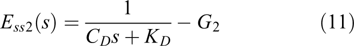
where Xe is the impedance position deviation, FL is the external load force, CD is the desired damping of the system, and KD is the desired stiffness of the systems is Laplace Operator.
State space expression of impedance control system for HDU
Since the actual effective working area of the servo cylinder in HDU is much smaller than the actual effective working area of the ordinary hydraulic cylinder, the slight change of the output flow of the servo valve will directly affect the output position and speed of the piston rod. The linearization method is used to deal with the specific working point of the slide valve part in the servo valve, which cannot truly reflect the flow output characteristics of the whole dynamic process of the servo valve. Therefore, this article preserves the pressure-flow nonlinearity of the servo valve and derives the state space expression of the position-based impedance control system of the HDU.
The mathematical model of each link of the HDU adopted in this article is the same as the mathematical model of each link of the HDU established by the author in the previous period.
30
–32
To reduce the length, this article will not repeat them. According to the mathematical model of the HDU established in the previous period, five linearly independent system variables are selected as the state variables of the control system for the position-based impedance control system. These variables are
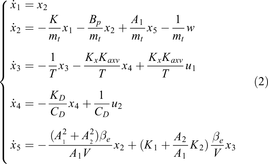
where
where Kd is the equivalent flow coefficient, xv is the servo valve spool position, ps is the system supply oil pressure, p1 is the left chamber pressure of the servo cylinder, p2 is the right chamber pressure of the servo cylinder, p0 is the system return oil pressure, W is the area gradient, A1 is the nonrod cavity area of the asymmetric servo cylinder, A2 is the rod cavity area of the asymmetric servo cylinder, xp is the piston position of the servo cylinder,
Thus, equation (2) can be expressed as follows

where
According to the derivation of the state space expression of the position-based impedance control system, the system block diagram can be established, as shown in Figure 3.

Block diagram of position-based impedance control system.
According to the derived state space expression of the position-based impedance control system, the “rank criterion” is adopted to judge the observability of the system, and the “PBH rank criterion” is adopted to judge the controllability of the system. 33 Analysis of the position-based impedance control system is observable and controllable, and the proof process is not listed in detail due to length limitations. SFC adopts the state variables of the system for feedback control, so that the poles of the system are assigned to the desired position to improve the dynamic response and control accuracy of the system. Therefore, SFC needs to complete two parts of research: First, to obtain the state feedback matrix. Second, to obtain the state variables of the system.
Introduction of SFC
Construction of state feedback matrix
Obtaining the state feedback matrix is one of the key problems of SFC. 34,35 When the desired poles of the system are known, the pole assignment method is generally adopted to obtain the state feedback matrix of the system, but for high-order systems, it is difficult to obtain the desired poles. Therefore, it is not appropriate to adopt the pole assignment method to obtain the high-order state feedback matrix of the system. The position-based impedance control system is an infinite-time output tracker problem among the linear quadratic problems. At present, there is no strict general solution to the infinite time output tracker, but the output tracker and the output regulator have the same feedback structure. Therefore, this article solves the state feedback matrix through the infinite-time output regulator.
For the infinite-time output regulator of the linear time-invariant system, the control objective is to design the optimal control law so that the system error and the control energy are simultaneously minimized, so the performance indicators are shown as follows
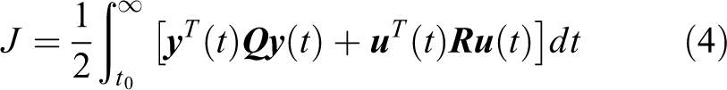
where
By constructing the Hamiltonian function, the state feedback matrix can be obtained as follows

where the
Assuming the reference input vector

After the state feedback is introduced to the original position-based impedance control system

The system represented by equation (7) can be abbreviated as
Block diagram of position-based impedance control system with state feedback.
Design of input converter amplifier
When the state feedback matrix of the system is determined, the tracking error of the system is also determined. To improve the steady-state accuracy of the control system, the input transformation amplifier F is introduced. The input transformation amplifier is obtained with the goal that the steady-state error of the system be equal to zero. After adding the input transformation amplifier F to system

Block diagram of the state feedback control system with input converter amplifier.
Assume the state feedback matrix


According to equations (8) and (9), the error transfer functions of the two inputs of the system are obtained as follows

When time tends to infinite, the system reaches a stable state. At this time, the steady-state error of the system is determined according to the final value theorem, as follows


Since the expected steady-state error of the system is zero, both equations (12) and (13) are zero. Combined with the equations from equations (8) to (13) and MATLAB auxiliary calculation, it can be obtained as follows

Design of the full-dimensional state observer
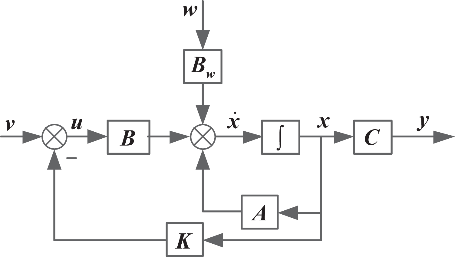
The obtained system state variable is another key problem for SFC. In real systems, due to the limitation of equipment space and economy, it is impossible to obtain all state information of the system. As a result, it is difficult to realize and popularize the SFC. In this article, the full-dimensional state observer 28 is adopted to track and observe the five state variables of the system. After adding the full-dimensional state observer, the system block diagram is shown in Figure 6.
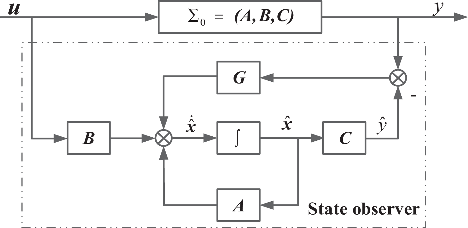
System block diagram with state observer.
As shown in Figure 6, the full-dimensional state observer has two inputs: one is the input of the real system, and the other is the difference between the output of the real system and the output of the state observer. The reaching speed of the observed state variables and real system state variables can be controlled through the output error feedback matrix G from the state observer. Therefore, the design of the full-dimensional state observer is based mainly on the selection of the matrix G. Generally, when the closed loop pole of the state observer is n (n > 1) times as much as the desired pole of the controlled system,
36
the convergence speed of the state observer and accuracy meet the requirements. From the previous analysis, the state feedback matrix
Assume that the expected poles of the position-based impedance control system of HDU are p1, p2, p3, p4, and p5, respectively, and the expected pole of the full-dimensional state observer is k times as much as the expected pole of the position-based impedance control system, then the expected characteristic polynomial of the full-dimensional state sensor is as follows

After adding the state feedback, the characteristic polynomial of the full-dimensional state observer coefficient matrix

Through equations (16) and (17) with the same power coefficient

A position-based impedance control system for HDU is formed by combining the state feedback matrix, the input transform amplifier, and the full-dimensional state observer, and the block diagram of the SFC system with full-dimensional state observer is formed, as shown in Figure 7.
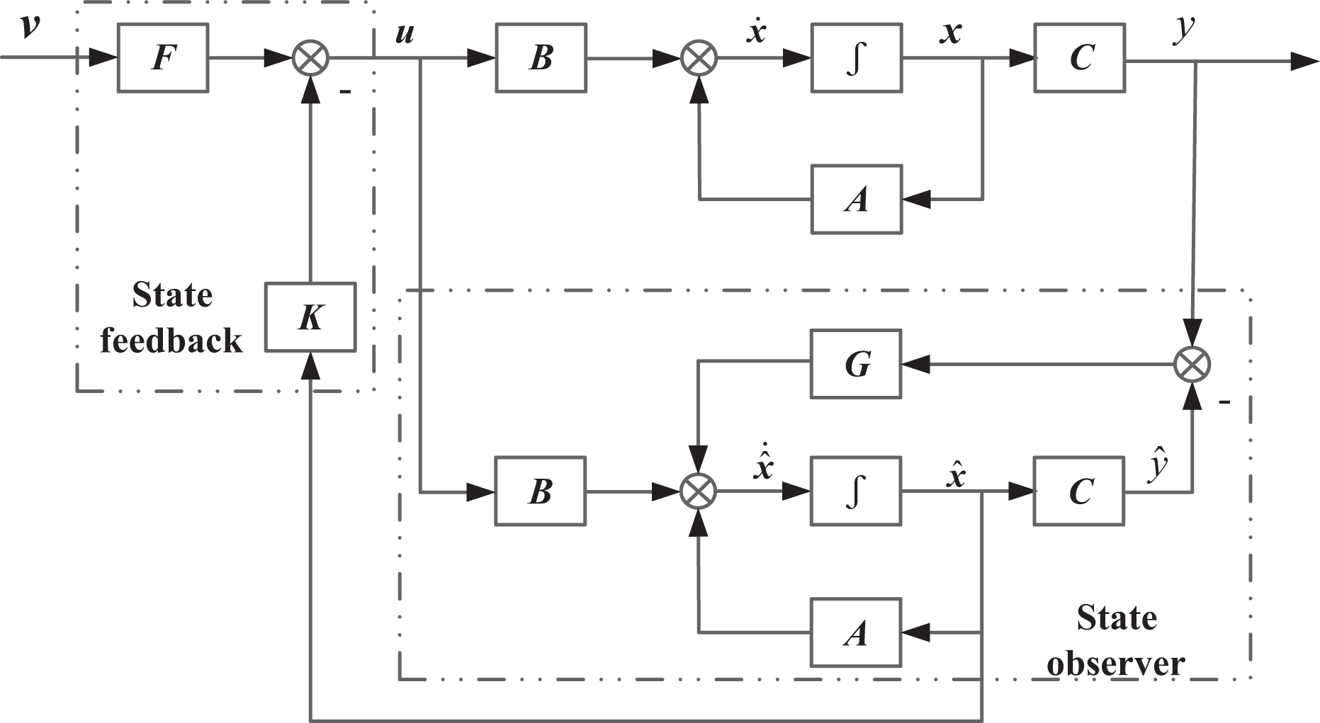
Block diagram of state feedback control system with full-dimensional state observer.
Estimation of time-varying parameters of servo valve flow
In this article, to reduce the influence of servo valve flow linearization on the accuracy of the model, the nonlinearity of the servo valve pressure flow is preserved, and the nonlinear state space expression of the system is derived. Therefore, the state feedback matrix, input transformation amplifier, and the output error feedback matrix of the state observer obtained in this article are all time-varying matrices. To carry out the SFC of the system, it is necessary to estimate the time-varying parameters of the servo valve flow in real time and calculate three time-varying matrices in real time.
Assume the load pressure of the system is


Regardless of the compressibility and leakage of the oil, when the cylinder rod of the hydraulic cylinder protrudes outward, that is,

equation (21) is simplified as follows

Combined with equations (22) and (20), then

Combined with equations (23) and (5), then

Regardless of the compressibility and leakage of oil, when the hydraulic cylinder rod is retracted, that is,

equation (26) is obtained by simplifying equation (25) as follows

Combined with equations (26) and (20), then

Combined with equations (27) and (2), then

In summary, according to equations (22) and (26),
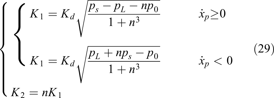
where the load pressure can be expressed as
equation (29) shows that the force sensor can estimate the flow time-varying parameters of the servo valve in real time, and the state feedback matrix, the input transformation amplifier, and the output error feedback matrix of state observer can be calculated in real time. Finally, the SFC of this article is formed.
Experiment
Introduction to the experimental system
The experimental system adopted in this article is the HDU performance test platform, as shown in Figure 8.
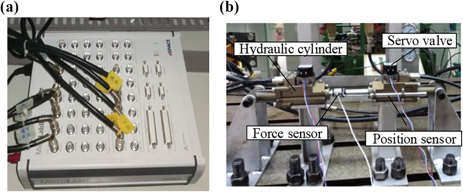
Physical diagram of controller and top-to-top mechanism. (a) dSPACE controller and (b) experimental system top-to-top mechanism.
As shown in Figure 8(b), the HDU on the right side is the test system, where the system performs position-based impedance control to verify the SFC. The left HDU is the experimental loading system, which is adopted for force servo control and used to apply load to the position-based impedance control system of the left HDU.
Experimental results
The experiments in this article are divided into two parts: First, to verify the effectiveness of the full-dimensional state observer. Second, to verify the effectiveness and advantages of SFC by comparing output feedback with PID control.
Experiment for full-dimensional state observer
At the initial moment of all experiments in this article, the piston rod position of HDU is set at 25 mm. To verify the tracking ability of the full-dimensional state observer to the state variables of the experimental system, the experimental conditions presented in Table 1 were designed to verify the full-dimensional state observer. Because the experimental system could not provide all the state variable information, in this article, the full-dimensional state observer is verified by combining the simulation model of HDU position-based impedance control. The model is built with MATLAB/Simulink software (MATLAB/simulink 2016b) and modified by experiments, which can better represent the real system. To reduce the length, this article does not elaborate on the modeling process.
Experimental verification of full-dimensional state observer.

When the system inputs the 4 mm step signal under condition without load, the curve shown in Figure 9 is obtained. When the system inputs the 6 mm amplitude and 2 Hz sinusoidal input signal under conditions without load, the curve shown in Figure 10 is obtained. When the system inputs the 6 mm amplitude, the 2 Hz sinusoidal input signal under the condition with 500 N amplitude and 0.5 Hz load force, the curve shown in Figure 11 is obtained.

The 4 mm step signal under condition without load. (a) Position comparison curve, (b) velocity comparison curve, (c) spool position comparison curve, and (d) load pressure comparison curve.

The 6 mm amplitude and 2 Hz sinusoidal input signal under condition without load. (a) Position comparison curve, (b) speed comparison curve, (c) spool position comparison curve, and (d) load pressure comparison curve.

The 6 mm amplitude, 2 Hz sinusoidal input signal under conditions with 500 N amplitude and 0.5 Hz load force. (a) Position comparison curve, (b) speed comparison curve, (c) spool position comparison curve, (d) impedance position comparison curve, and (e) load pressure comparison curve.
Panel (a) in Figures 9 to 11 show that the full-dimensional state observer has high tracking accuracy for the output position of the experimental system, and the position tracking curve basically coincides with the detection position of the displacement sensor. Panel (b) in Figures 9 to 11 shows that the full-dimensional state observer has a certain tracking ability for the piston rod speed of the experimental system. When the system is a step input, its speed changes drastically. The observed speed signal has a small error from the actual speed of the system, but its change trend and order of magnitude are basically the same. When the system inputs sinusoidal signal (no load force or load force), the observed speed is basically the same as the actual speed. Panels (c) and (d) in Figures 9 and 10 as well as the panels (c) and (e) in Figure 11 show that when the full-dimensional state observer observes the spool position and load pressure of the system, the trend and the order of magnitude of the observed signals are the same. When the system input is a step signal, the error between the two is larger than the error when the system is a sinusoidal input. Panel (d) in Figure 11, when the system is under condition with load force, shows that the full-dimensional state observer has the same tracking trend and order of magnitude for the impedance position.
In summary, by comparing experiments and simulations, the full-dimensional state observer designed in this article has a high accuracy observation capability for the state variables of the position-based impedance control experimental system, which provides a guarantee for the state feedback of the system.
Experiment for SFC
To verify the difference between the SFC and the output feedback and PID control and to reflect the excellent performance of SFC, the experimental conditions presented in Table 2 are designed to verify SFC.
SFC and output feedback and PID control comparison experimental conditions.

SFC: state feedback control.
When the system inputs the 2 mm step signal under the condition without load, the response curve shown in Figure 11 is obtained. When the system inputs 3 mm amplitude, 0.5 Hz sinusoidal signal under conditions without load force, the response curve shown in Figure 12 is obtained. When the system inputs 3 mm amplitude, the 0.5 Hz sinusoidal signal under conditions with 1000 N constant load force, the response curve shown in Figure 13 is obtained. When the system inputs 3 mm amplitude, 0.5 Hz sinusoidal signal under condition with 1000 N amplitude, and 2 Hz sinusoidal load force, the response curve shown in Figure 14 is obtained. When the system inputs 6 mm amplitude and 2 Hz sinusoidal signal under condition without load force, the response curve shown in Figure 15 is obtained. When the system inputs 6 mm amplitude and 2 Hz sinusoidal signal under condition with 500 N constant load, the response curve shown in Figure 16 is obtained. When the system inputs 6 mm amplitude and 2 Hz sinusoidal signal under the condition with 500 N amplitude and 0.5 Hz sinusoidal load force, the response curve shown in Figure 17 is obtained.
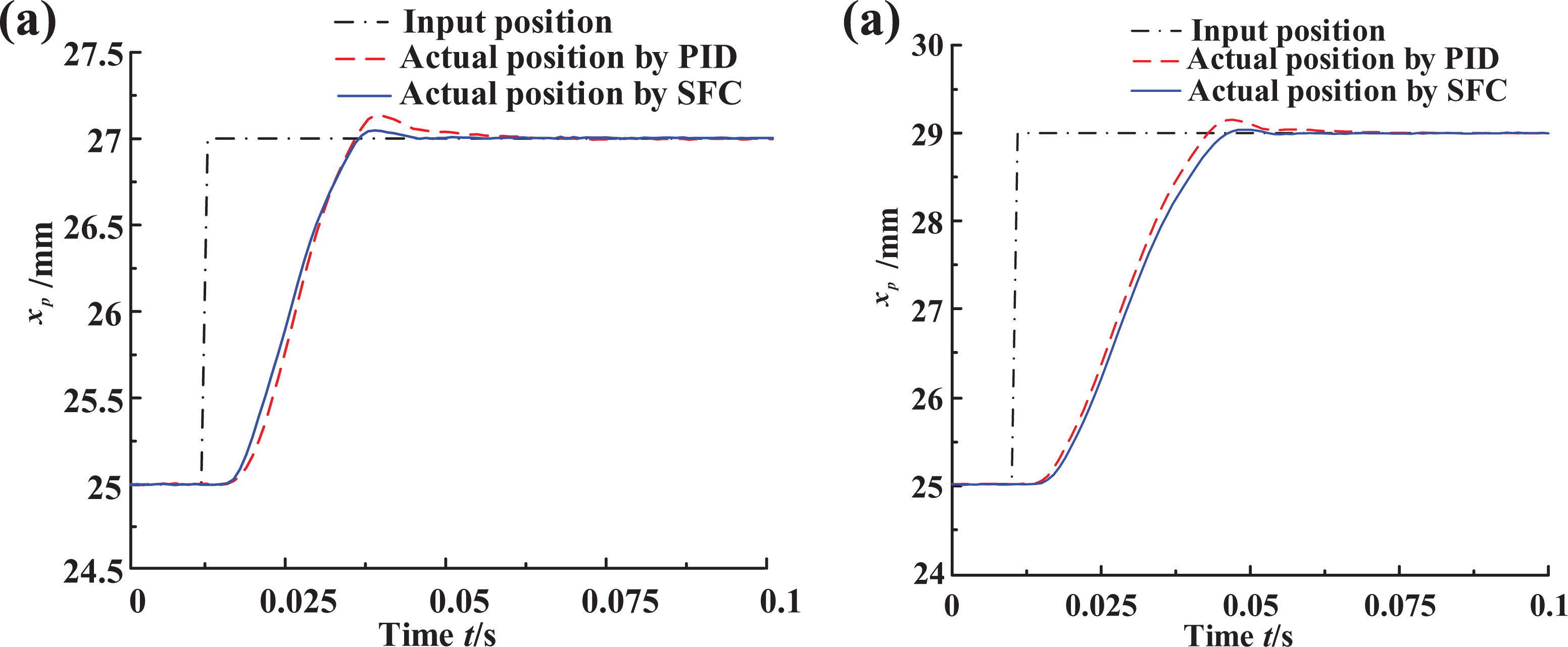
Stepwise working conditions. (a) Step 2 mm response curve and (b) step 4 mm response curve.

The 3 mm amplitude and 0.5 Hz sinusoidal signal under conditions without load force. (a) Response curve and (b) error curve.

The 3 mm amplitude and 0.5 Hz sinusoidal signal under conditions with 1000 N constant load force. (a) Response curve and (b) error curve.

The 3 mm amplitude and 0.5 Hz sinusoidal signal under conditions with 1000 N amplitude and 2 Hz sinusoidal load force. (a) Response curve and (b) error curve.

The 6 mm amplitude and 2 Hz sinusoidal signal under condition without load force. (a) Response curve and (b) error curve.

The 6 mm amplitude and 2 Hz sinusoidal signal under conditions with 500 N constant load. (a) Response curve and (b) error curve.
To show the difference between output feedback and PID control and SFC in the position-based impedance control system more intuitively and concretely, the rising time and maximum overshoot of the step response curve are selected as its performance evaluation index, and the maximum error and maximum error reduction rate of other response curves are selected as its performance evaluation index. “Maximum error reduction rate” in Table 4 represents the difference between the maximum error of PID and SFC divided by the maximum error of PID, which clearly shows the difference between the two effects. Based on these parameters, the performance evaluation indices presented in Tables 3 and 4 are made.
Performance evaluation table under step input conditions.

Performance evaluation table under sinusoidal signal input conditions.

SFC: state feedback control.
Figure 12 and Table 3 show that when the step amount is the same and the rising time is basically the same, the maximum overshoot of the system adopting SFC is smaller than the maximum overshoot of the system adopting PID control, which is approximately 27% of the maximum overshoot of PID control.
Figures 13 to 18 and Table 4 present that when the system input is a sinusoidal signal and the load force is zero, a constant value or a sinusoidal signal, respectively, the maximum error of the system adopting SFC is smaller than the maximum error of the system adopting PID control, and the maximum error reduction rate varies with different working conditions of the system. When the position input of the system is the same and the load force is zero, constant, or sinusoidal, respectively, the maximum error of the system increases successively. At this time, compared with PID control, the maximum error of the system is smaller when SFC is adopted, and the maximum error reduction rate, respectively, decreases with the conditions that the load force is zero, constant value, or sinusoidal.

The 6 mm amplitude and 2 Hz sinusoidal signal under condition with 500 N amplitude and 0.5 Hz sinusoidal load force. (a) Response curve and (b) error curve.
In summary, when the position input of the system is step or sinusoidal and the load force input is zero, constant, or sinusoidal, compared with the PID control, SFC can make the maximum error of the system smaller and improve the tracking performance of the system. After the position-based impedance control system adopts SFC, the control performance of the system is better, and the flexibility of the robot is better.
Conclusions
Based on the above research, the following conclusions were obtained in this article: The nonlinear state space expression of the system is established, the state feedback matrix is obtained based on the solution of linear quadratic optimal control, the input transformation amplifier is obtained based on the steady-state error of the system, and the full-dimensional state observer is designed to track and observe the state variables of the real system. Based on the real-time estimation of flow parameters of servo valves through the front-end force sensor of the hydraulic rod in the HDU, the state feedback matrix, input conversion amplifier, and output error feedback matrix of state observer are calculated in real time. SFC of the position-based impedance control system with dual input and single output is formed. Through the analysis of the experimental curve and performance evaluation table, the full-dimensional state observer designed in this article has a good tracking ability and accuracy for the state variables of the HDU experimental system. Compared with the traditional output feedback and PID control, SFC has better dynamic response and higher control accuracy. Therefore, the position-based impedance control system adopting SFC has better control performance, which can provide better compliance performance for the hydraulic-driven legged robot to alleviate the impact force in the collision process between the foot and the ground more effectively.
Footnotes
Declaration of conflicting interests
The author(s) declared no potential conflicts of interest with respect to the research, authorship, and/or publication of this article.
Funding
The author(s) disclosed receipt of the following financial support for the research, authorship, and/or publication of this article: This work was supported by the National Key R&D Program of China under grant no. 2018YFB2000701, National Natural Science Foundation of China (grant no. 51975506 and 51905465), and Youth Talent Promotion Project of China Association for Science and Technology (grant no. QNRC0246).