
Abstract
Industrial cameras starting to play a significant role in current industrial environment and they represent a strong tool for robotics mainly in cases when they are combined with high-speed robots. However, there are still some difficulties in vision system integration. The capability of such system (e.g. assembly or technological system) depends on several factors, for instance, the camera position, lightning conditions, pattern recognition algorithms, precise setup, as well as well-trained programmer and engineer. The skills of the engineering staff and the precise analysis of conditions and process requirements seem to be crucial for successful solution, what was proved also in our experimental test. The main aim of the article is development and complex performance analysis of robotized screwing application with integrated vision system, concretely the case study of automated assembly system in automotive industry—bolting tightening robotized station as a part of car seat assembly process. The main key elements of the designed workplace are industrial robot FANUC M-20iA/20M with integrated iRVision system containing the industrial camera Sony XC-56. The real influence of inaccuracies during the design process, gradual “step-by-step” refinement, and final influence of all changings on the final quality and efficiency of designed system was demonstrated. At the end, we reached the point where the total number of screwing operations with NOK results (not OK / negative results) is about six single negative results per day, which represents less than 0.1% of all recognitions (overall reliability is higher than 99.9%).
Keywords
Introduction
Several authors (for instance, Küpper and Kuhlmann 1 ) mentioned that advanced digital technology is already used in industry; however, with Industry 4.0, it will transform the production to smarter automation in various ways via installing of smart robots, sensors, using of collaborative robots, applying production simulations, and so on.
Nowadays, there are constantly appearing new applications in robotics and its specific branch, namely vision guided robot systems (VGR systems) where the so-called machine vision (MV) systems have found their strong usage. General VGR system is basically any robot system where the feedback for precise robot navigation to a variable target position is provided via at least one industrial camera. 2,3 As a result, their application can reduce total costs and make it possible to solve tasks that would not be possible without the usage of such cognitive sensors. The main motivation for VGR systems usage in robotics is to replace human cognitive capabilities (visual sense and decision-making) to perform wide variety of tasks where the ability to adapt to variable conditions is strongly required or mandatory. Their main purpose is obtaining information and on this basis controlling processes or machines via proper interpretation of scene’s image achieved through the optical contactless sensing system.
Modern advanced sensing systems based on “smart camera sensors” have been quickly spread into many fields of industry, such as general process control, 4 general object identification and recognition, 5 quality check (Stejskal, Bayraktar, Alghamdi), 5 –7 reading texts and codes (e.g. car identification plate), 8,9 face recognition (Park), 10 robot control via gestures 10 and general pose control of robots using visual servoing, 3 visual navigation of single/multiple mobile robot/s (Kim, Ostertag, Mikulova, Roberti), 11 –14 collision detection and perception (Lehnhardt), 15 many applications in food industry, and online process control and monitoring (Kosinar) 16 using component recognition (Stipancic, Scholz-Reiter). 17,18 Smart sensors are key elements for visual inspection of parts or visual navigation of robots for assembly tasks that has been manually done by human operators before.
Inclusion of large data sets is often necessary by the nature of cognitive sensory systems. Proper simulation can be utilized with both real pictures and synthetic images to minimize any negative effects of processing such extensive data sets. 19 Bayraktar and his colleagues 6 proposed method for efficient processing of hybrid image data sets. Due to the nature of the processed data, VGRs must be able to learn and to “understand” the scene in real world, so they are often closely related to different approaches of artificial intelligence. Since they show better results for some specific tasks, many studies are being conducted on neural networks application (Park) 10 or combination of machine learning algorithms. 2,8,10,20
While the MV market offers various types of vision systems, such as PC-based systems, Smart Camera vision system, and hybrid Smart Camera vision system, 3 for most tasks, VGR systems are sufficient to apply two-dimensional (2D) MV systems based on data collection from single camera. 15,20 On the other hand, for more advanced tasks (like, e.g. the so-called bin-picking), it preferred the three-dimensional (3D)—stereo camera system. 21,22 Although the sensor Kinect has gained notoriety for 3D scanning of industrial robot environment (for instance, Bobovsky, Ghani), 23,24 it is not entirely appropriate for such robot navigation where the high positioning accuracy is required. In general, this type of sensor uses an indirect method of sensing the world based on the 3D space transformation into 2D image information, whether perpendicular or perspective projection is defined. Mario Claer 25 pointed out that it is becoming increasingly important for the robotic system to be able to perceive its surroundings in 3D in specific areas. Scanner based on light detection and ranging method for measuring distance of obstacles (LiDARs) and other kind of 3D scanners are therefore often used for similar tasks, even though their field of vision is smaller. This disadvantage can be eliminated in several ways, mostly by mounting on different types of rotary platforms.
Among the advanced camera systems, we can classify above all visual navigation of mobile robots and self-driving cars, human body gesture or face keypoints recognition, and so on. The application of MV system in autonomous navigation of mobile robots and self-driving cars is mentioned in authors such as Kim, 11 Claer, 25 and others. Jeong-Hyun Kim 11 proposed the so-called Self-Organizing Map algorithm to obtain suitable data about the position of objects in space based on depth data from a stereo camera. This system is used to analyze the front part area of a vehicle in forms of several candidate planes. Kocic et al., 26 in their study, presented a short overview of available sensors and basic rules for sensor fusion in area of autonomous vehicles navigation as well. Park 4 and many others focused their research on MV for human body gesture or face keypoints recognition. Research in this area becomes popular in the last 10 years mainly for robot control. Other interesting application of MV is presented in article written by Christie et al., 27 where a vision alarm system for rock crusher is presented. Bozek 28 and his colleagues proposed a new method for analytic solution of trajectory calculation for precise robot control along the advanced trajectories. Bako et al. 29 and Dizo 30 are dealing with increasing the efficiency of robotized production lines including grasping of object via simulation tools, which can significantly reduce the bottleneck occurrences and handling accidents. Labudzki 31 created the review article about capabilities and applications of MV systems, while Kim 9 focused on neural network usage for MV.
This article describes a case study about performance analysis and development of robotized screwing application with integrated vision sensing system for automotive industry. Imaging analysis with iRVision systems is applied to finding the real position of screws in the target region. In this article, we have designed and tested the Recliner bolting station for the task of autonomous screwing operation of four bolts connecting the back frame with the seat frame of the car seat. The key element of assembly process is application of vision guided robotic system for screwheads recognition and obtaining their precise current position within defined range. The functionality of all key features—station design, chosen equipment, designed recognition procedure, proposed methods, and the designed program—was proved via experimental verification and for more than 2 years run as a part of whole production line.
Task formulation and basic workplace configuration
The task is to design and implement the VGR system for bolting operation—tightening of four screws (bolts) connecting the back frame and bottom frame of the seat. Final cell will replace the human operator from economic, as well as ergonomic reasons. Whole system must be designed as an integral part of existing assembly line for passenger car seats produced by an external customer. Total average production capacity of the production line is defined as 1000 “car sets” (pair of front seats − one left (LH) and one right (RH)) per day. The real production capacity can vary with respect to the customer requirements. It means that average number of “screwing cycles” is about 8000 per day (1000 LH + 1000 RH and for each of them four screws).
The basic requirements are summarized in Table 1. The workcell and the assembly components are shown in Figure 1.
Basic requirements defined by the customer.a

a“Car set” contains a couple − one left and one right seat.

The Bolting station definition—basic structure of the workcell (left), detail of scanned area for finding of screws (right down), screwing order definition (right up), and detail on prescrewed bolt in position how is entering the station (middle).
Workplace structure and equipment
The first goal is to design the robotized bolting workcell, concretely to select suitable equipment and to design all systems to work as one fully integrated automated robotized assembly system according to the requirements (Table 1). So it will be necessary to combine utilizing a six-axis FANUC robot, 2D vision system, and a conveyor system of the production line. The station is under the supervising of higher level control system for whole production line—so it is has to be synchronized with all other processes by manufacturing execution system (MES) system. The main reason why VGR system was required is that the seat setting can vary regarding the previous operations—they can enter the bolting station with different setup in both directions—position of height adjustment lever as well as in horizontal direction.
Robot FANUC M-20iA/20M
The company FANUC Robotics provide a variety of robots for different purposes. 32 We decided to apply the robot FANUC M-20iA/20M 33 with R-30iB controller series in this project. Chosen version of the robot is capable to do degrees of freedom (6-DOF) motion of end effector within the spherical workspace with maximum diameter 1860 mm, while maximum payload is limited to 20 kg included the end effector (see Table 2). The main advantage lies in the effective combination of stiffness, payload, reach, and axis speed. FANUC R-30iB robot controller is compact and easy to integrate into single robot production cells and it is ready for intelligent functions such as vision, force, and interference check as standard. We chose the version with “Mate Cabinet,” which is powerful and self-contained and has been designed specifically for M series and LR-Mate robots. For robot control, setting and programming were applied the teach pendant with touch screen.
Basic technical specification of robot FANUC M-20iA/20M. 33
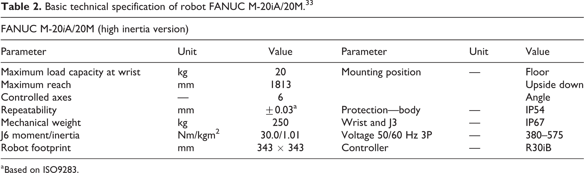
a Based on ISO9283.
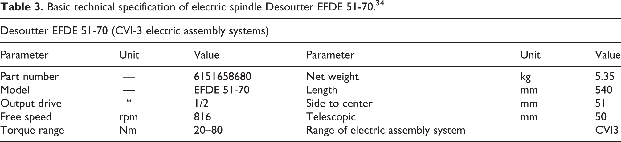
Screwdriver—spindle Desoutter EFDE
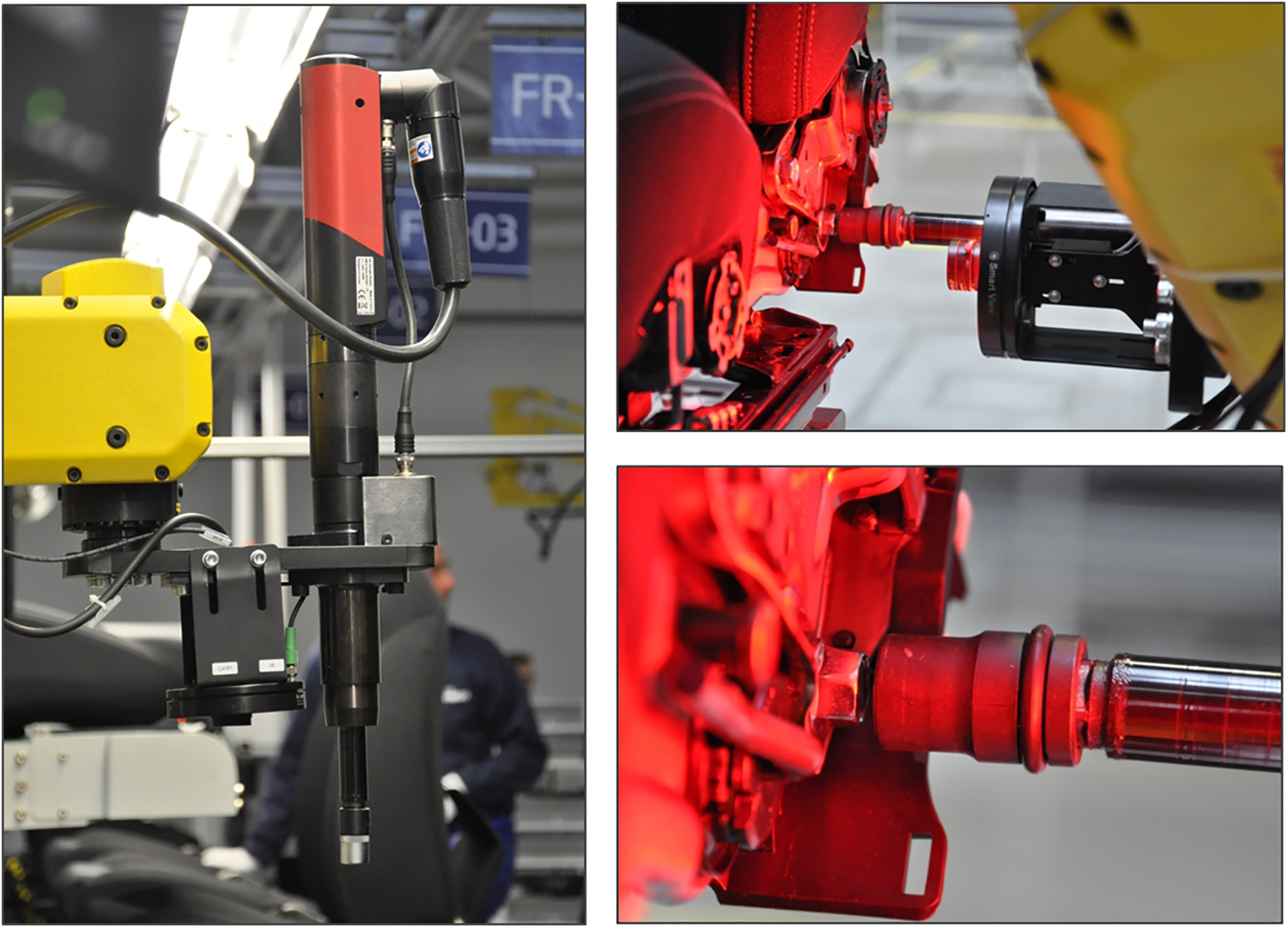
The inline fixtured spindle Desoutter EFDE 51-70 (Figure 2; Table 3) as the main tool was used—part of Desoutter CVI3 assembly system developed especially for automotive industry. Dedicated to meet the demanding requirements of this industry segment, the CVI3 platform assures the robust screwdriver design based on brushless motor combined with the torque transducer and traceability of all the safety critical application process. The integration of error proofing modules is easy to adapt to each application.

Tool for screws tightening—electric spindle Desoutter EFDE 34 (right) and its control unit CVI3 (left).
Basic technical specification of electric spindle Desoutter EFDE 51-70. 34
Vision system—basic structure
The main aim of vision system is to provide the necessary data about shape and position of parts beneath the camera’s view range to the robot controller. FANUC robots are teaching-playback robots. 35 In a teaching-playback system, specific tasks are taught to robots in advance, which then in turn work exactly as they are taught according the robot program. 36,37 This means that, if you want the robot to do any operation with specific component in the same way, you need to place every component at exactly the same position. As a result, the production flexibility increases due to the eliminated need for expensive positioning fixtures. Unfortunately, this is not true in our case due to some different setting of every seat in production line.
The FANUC iRVision system is a fully robot integrated visual sensor system designed to eliminate such restrictions. 38,39 iRVision system uses one or more cameras to find the precise position and orientation (or other desired parameter, e.g. color, different size/scale factor) of each object within the scene and modifies preprogramed robot trajectory. So that the robot can do the same operation even if the position (orientation, etc.) of the objects is different from their position set when the robot program was taught. 38 The iRVision application solution can be implemented on any FANUC industrial robot equipped with suitable hardware card for its connection and can be customized (different capability 2D, 2½D or 3D vision, different tasks, etc.). The main advantages and reasons for application of integrated iRVision system are reduced capital and operating costs, reduced complexity of whole system, stable running due to the elimination of third-party hardware and software features, and high speed of vision communication and processing through robot backplane.
The 2D iRVision system is sufficient for the conditions of our application where it finds parts and their precise position and orientation (X, Y, Z, and R). Our iRVision system (schema in Figure 3) composed from camera Sony XC-56, the lens, proper light source, Ethernet cable/JRL6A port, and software platform Web server was installed on the FANUC M-20iA/20M robot to serve the robot guidance and to find position of screwheads.

General schema of FANUC iRVision system and connection of peripheral devices. 33
Camera
Here we applied the single camera Sony XC-56 (see Figure 4; Table 4) with lens fixed focus length, F1.8-1.4. It was not necessary to choose zoom lens type due to robot-mounted camera, so the proper focal distance can be reached by the position of the robot arm itself. Camera is mounted on the robot arm end effector—it is carried on common holder with the screwdriver (see Figure 4, right). This holder is connected with the flange of robot axis J6. The optical axis of both camera and screwdriver is parallel and offset 90 mm each other. The Sony XC-56 is a monochrome camera module that incorporates a 1/3 type progressive scan CCD. It has VGA resolution (647 × 493 pixels) output at 30 fps or optionally 60 fps. Various settings are available on the rear panel.

Camera Sony XC-56—rear and front view (left/middle) and its mounting on common holder with the screwdriver (right).
Basic technical specification of camera Sony XC-56. 40

W: width; H: height; D: depth; CCD: charge-coupled device; VGA: video graphics array; Ext.: external; DC: direct current; Op.: operating.
Lightning and filtering
The main objective of lighting for MV systems is to create the most favorable conditions for quality detection of required objects, in particular maximize the contrast between objects of interest and their background. In general, these conditions can be achieved by choosing suitable illumination source or combination of sources,
41
its or their position, light intensity, diffusion parameter, color, and so on.
3,8
Due to the difficult light condition around the production line, it was necessary to use individual light source. We were thinking about several alternatives: One light source carried at the robot end effector (moving with the camera). One light source carried at the robot end effector and one static diffuse bar light from above. Combination of one light source carried at the robot end effector, one static diffuse bar light from the ceiling, and one light source focused on each side of the seat mounted on the protection cage.
We have decided for second alternative with respect to ensure reducing costs, as well as to avoid possible collision of two side light sources with other objects within the protection cage or collision with conveyor itself. The standard light source commonly used in a given production line was chosen as the upper diffuse light source.
In our case, it is not possible to apply other lightning methods, such as backlight, side light, and so on. It is also not possible to change the properties and structure of top surface of the frame parts, which creates the background of the screws. So, the proposed vision system must therefore be robust enough to eliminate the negative effects of the scanned scene.
The SmartView Ring-light RL-100R60 and RL-100IR50 (see Figure 5; Table 5), respectively, can be used for flash lightning and for permanent lightning as well. The light can be connected via programmable logic controller (PLC) output and turned ON/OFF according to the task requirements. It can be operated by Trigger signal as well, while the intensity can be controlled by pulse width modulation (PWM) signal if necessary.

SmartView Ring-light RL-100R60 and RL-100IR50.
Basic technical specification of SmartView RL-100R60 and RL-100IR50.a

IR: infrared.
Together with choosing light sources, it is necessary to select proper filters, which will be mounted on the front lens. The general reasons for optical filters application are to correct white balance; remove or allow infrared (IR), ultraviolet, or selected color range; remove undesirable reflections; get higher spatial resolution; 23 gamut; extend the scanning time, and so on.
MV filters were mounted on the front lens tube. Several individual filters and their combination have been tested (see Figures 5 and 6).

Tested filtering elements—light red bandpass filter BP635-27 and linear polarizer PR032-27 and diffusor rings with different light transmission level.
Smart View RL-100R60 (red light) + filter Midopt BP635 (red light),
Smart View RL-100R60 (red light) + filter/linear polarizer Midopt PR032-27,
Smart View RL-100R60 (red light) + filter Midopt BP635 (red light) + filter/linear polarizer Midopt PR032-27,
Smart View RL-100IR50 (IR) + filter Midopt BP635 (red light),
Smart View RL-100IR50 (IR) + filter/linear polarizer Midopt PR032-27.
Best results were reached by IR ring light Smart View RL-100IR50 combined with light red bandpass filter BP635-27 and linear polarizer PR032-27 (both are made by company Midwest Optical Systems, Inc.—MIDOPT, 322 Woodwork Lane Palatine, IL 60067 USA 42 ) mounted on the frontal lens.
Vision system setup
Next step is the tool Vision Setup via iRVision WEB server platform. In general, there exist two different approaches for measuring of objects position in VGR navigation—absolute position measuring and finding the data about relative position offset (iRVision adopts this approach). So, in our case, camera system provides the data about distance between object’s actual position and the so-called reference position, and robot controller adjusts the final trajectory according to this distance.
On the one hand, the iRVision supports two kinds of robot position offset:
35
Fixed Frame Offset—the object offset is measured in a coordinate frame fixed with respect to the robot base. An object placed on a fixed surface is viewed by a camera, and the vision system measures its position. The robot then adjusts its taught positions, so that it can find the object properly.
Tool Offset—the workpiece offset is measured in a coordinate frame that moves with the robot tool. This method is useful for grippers where the part position in the gripper can vary, such as vacuum grippers. An object held by the robot is viewed by a camera, and the vision system measures its position relative to the gripper.
On the other hand, the following two types of camera mounting are selected:
Fixed Camera—camera is connected to the static frame (e.g. over the scene),
Robot-Mounted Camera—camera is carried on the robot arm.
Finally, there exist several possible combinations of both methods. Option 1: Fixed Camera + User Frame (UF) Offset (object is placed on the table), Option 2: Fixed Camera + Tool Frame Offset (object is placed in robot gripper), Option 3: Robot-Mounted Camera + UF Offset (camera is carried on the end effector and object is placed on the table).
With respect to the fact that the scanning process must be done from both left side and right side of the seat, we preferred option 3—Robot-Mounted Camera with UF offset. The principle of such configuration is shown in Figure 7.

Principle of configuration “Robot-Mounted Camera + User Frame Offset.” 31
The configuration procedure contains three steps (also the type of vision data), see Figure 8:

General schema of vision systems set-up procedure. 35
Camera Setup Tools—camera configuration (port number, the type of the camera, the camera mounting method, etc.),
Camera Calibration Tools—it establishes the mathematical correspondence between the camera coordination system and the world coordination system,
Vision Process Tools—it defines the image processing, location, and measurement to be performed by iRVision during production operation.
“Camera Setup Tool”—basic settings and camera configuration
Control system recognizes the type and parameters of connected camera automatically. Furthermore, we can manually adjust the focus ring (according to expected working distance from the subject) and the aperture control (according to expected lighting conditions). You can also change the zoom setting with another lens type. However, this is not available or not necessary in our case. We will adjust the working distance (chose the reference scanning position) to achieve a desired field of view (FOV) of approximately 150 × 150 mm for our application.
“Camera Calibration Tool”—basic settings
This step allows the robot control system to unify the relationship between the robot coordinate system and the camera FOV coordinate system. In case of FANUC robots, calibration is carried out by the means of the so-called 2D calibration grid with fixed spacing of optical calibration points (different sizes), in our case, 15 × 15 mm (Figures 9 and 10). Calibration is done with respect to a specific UF (in our case, UF2 or UF4, respectively; UF can be defined via three-point/four-point method). According to the used lens, the calibration projection can be defined—either orthogonal or perspective.
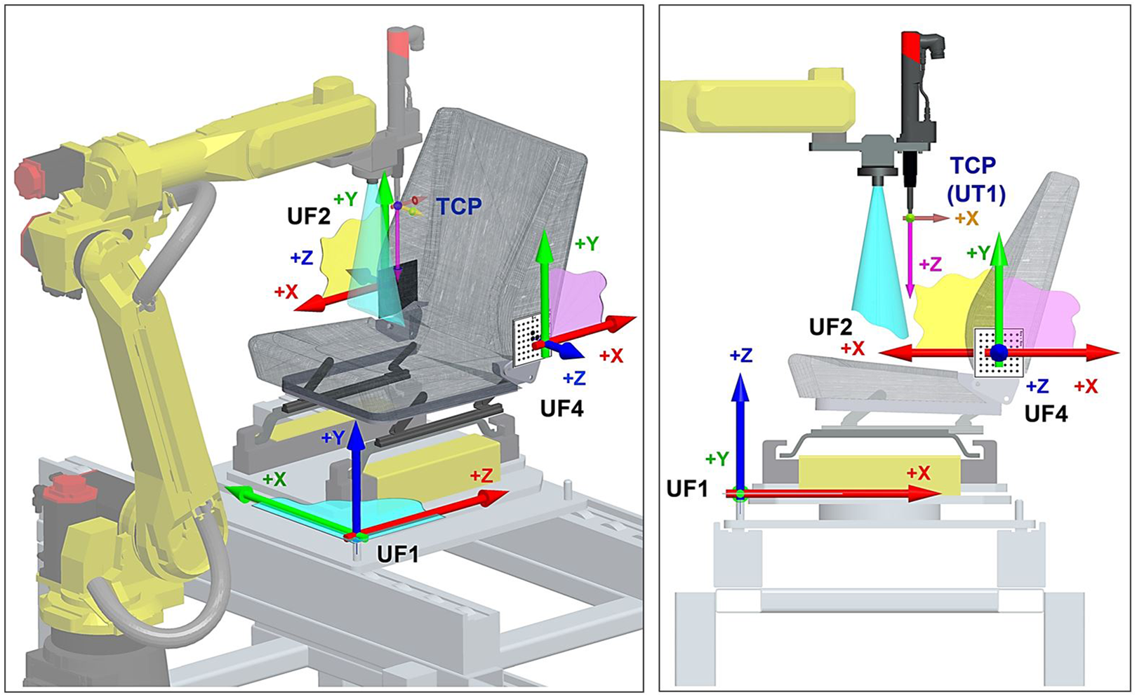
Defined UFs at the workcell. UF1: coordination system of the palette; UF2: coordination system of the left side (screws 1–4); UF4: coordination system of the right side (screws 2–3); UF: user frame.

Calibration process—touching the calibration grid to define the origin of user frame 2/4.
UFs definition
The UF defines the working space in which the robot works. The offset data from the vision system are all represented based on the UF. Therefore, it is very important to teach the UF as accurately as possible.
Table 6 lists all the defined UFs. We use UF6, 7, 8, and 9 for switching between LH and RH seat within the program. The main difference between both seats lies in the horizontal shift 25 mm along the axis X (UF1). So, when the program for RH seat is running, the UF6 and 8 are loaded into UF2 and 4. While the program for LH seat is running, the UF7 and 9 are loaded into UF2 and 4. For such operation, the following instructions can be used:
UF coordinates and configuration.

UF: user frame.
PR [32] = UFRAME [7]; Loading the UF7 data into position register no. 32.
UFRAME [2] = PR [32]; Loading the position register no. 32 into UF2 (for LH).
PR [34] = UFRAME [9]; Loading the UF9 data into position register no. 34.
UFRAME [4] = PR [34]; Loading the position register no. 34 into UF4 (for LH).
In the case of a 2D vision application, the UF covers another important role. It defines the 2D work plane in the real 3D space. The 2D work plane for iRVision must be parallel to the X–Y plane of the UF.
Each robot has different calibration requirements based on their applications, such as different cameras dependent on the type of vision system used which accompanies the specific robot purchased.
36
Difficulties in the process of vision control developing process to cope with were: Localization of object of interest, in which the camera must be calibrated to locate the workpiece under the exposure area shown in Figure 4; Lighting conditions where the appropriate consistent lighting for the process must be determined prior to image collection; Image segmentation in which appropriate time segments must be utilized for the camera to collect quality images; Image quality as the black-and-white photography must be reviewed for high quality, and finally, processing speed as higher processing speeds increases the efficiency of the process.
7
Calibration for UF4 (screws 1 and 4, LH)
We have done two separate Camera Calibration Tools for each seat from the “car set”: LH_Calbration_S_1and4_A, LH_Calbration_S_2and3_A, RH_Calbration_S_1and4_A, RH_Calbration_S_2and3_A.
The calibration method will then be described on the LH_Calbration_S_1and4_A. The same process was then repeated for all other calibrations. First of all, it is necessary to choose the fixture position—position of coordination system origin touched by the end effector (Figure 10). When we click the button “Set fixture positon,” iRVision system automatically calculates the grid position within UF (coordination system). Second step is choosing proper calibration position. The so-called two-plane method is recommended to prefer for Robot-Mounted Camera configuration (camera is carried on the robot end effector)—the calibration is done in two planes about 150 mm apart one another. This process can eliminate the optical distortion in optical elements and improve the precision of calibration data. The same process can be used when the camera is static and calibration grid is moving on the robot arm.
Calibration in first plane
We jog the robot into position P2 (Table 7), where the camera optical axis going through the UF4 origin in distance 325 mm measured from front edge of camera lens ring from calibration grid (Figure 11). Then we turned the light on and take the picture (SNAP button). When the grid is visible, the button FIND at “first plane” label can be used.
Calibration points for “two-plane method.”


“Two-plane method” of calibration done by iRVision system.
Calibration in second plane
We manually jog the robot into position P3 (Table 8, about 150 mm closer/farther from P2), then repeat the above steps for the second plane.
Reference position P1 for screw no. 1, LH.

LH: code for left seat / left seat palette; NUT: code for robot specific configuration.
Calibration refinement—deleting points that flew out
The displayed distance between the centers of the green crosshairs and red crosshairs plotted on the image represents an error. A smaller value indicates more accurate calibration. If a crosshair is displayed at specific location where no grid point is present (Figure 12, left side), we can enter the index number of that point in the text box and then click the Delete button. The specified point is deleted from the list, and the calibration data are automatically recalculated (Figure 12, right side).

Calibration refinement—deleting points that flew out.
After this step, the calibration refinement for screws 1 and 4 can be considered as finished. The same process will be done for the second side of the seat—the grid for screws 2 and 3.
Vision process tools
The next step is to define Vision Process Tool for each search process separately—that means for each component, part, or feature. In our case, we have created a total of eight unique search tools with attribute as 2D-Single-View Vision Process Tool—each for one screw of LH seat/RH seat (see Figure 13):

Setup process of 2D-Single-View Vision Process Tool for LR_SCREW_1_A: pattern teaching (up), pattern finding (middle), and setup of GPM Locator Tool parameters (bottom).
LH_SCREW_1_B_IRL/RH_SCREW_1_B_IRL—for the screw no. 1,
LH_SCREW_2_B_IRL/RH_SCREW_2_B_IRL—for the screw no. 2,
LH_SCREW_3_B_IRL/RH_SCREW_3_B_IRL—for the screw no. 3,
LH_SCREW_4_B_IRL/RH_SCREW_4_B_IRL—for the screw no. 4.
At first, it is the definition of GPM Locator Tool—basically searching pattern definition. The next step is the parameters definition for pattern recognition according to the GPM Locator Tool. Setting the reference position, the offset value is calculated based on the relationship between the reference position and the current found position. In this step, the part height Z if the part position is above/below the application UF can be entered.
At the beginning, it was necessary to jog the robot to the required working position for each component. In our case, we navigate the robot to a position of 3 mm above the head of selected screw. Then, we remember the coordinates of given position into the control program as any standard point P[n] (an example for P1 coordinates for screw 1, LH is listed in Table 8). This is how we got our reference location. Whenever a given object changes its position, the specific Vision tool is activated by RUN_FIND function, and the relative distance between the current and reference positions is measured and stored in the Vision Register VR[n] via GET_OFFSET function. Then, we apply the VOFFSET VR[n] function for specific point P[n] in the program. If RUN_FIND function does not return a value (the object is not found), the search process is repeated until the recognition is done successfully.
Experimental verification and improvement
During the experimental verification, we identified many factors which have different (positive or negative) influence for the recognition results as well as overall quality of screwing process. Further, we describe some experiment results.
Influence of the distance between camera lens and screwhead
At the beginning, the task definition contains requirement that all screws will come prescrewed from previous production sequence, but their exact position will depend on operator—so some seats will come with contact between screwhead and seat frame contact surface and some others will come with screws about 10 mm over the frame contact surface (only few revolutions). We have recognized that in some cases, there was negative influence of the distance between camera lens and screwhead (number of screw revolutions) on vision process (see Figure 14). It can be improved by elasticity (E) parameter. However, this solution is not completely sufficient.

Influence of the distance between camera lens and screwhead: (a) Screwhead is about 5 mm over the metal frame. RH, screw 1: elasticity 1 pixel; distance between camera front lens and screwhead = 177 mm; (b) Screwhead is about 12 mm over the metal frame. RH, screw 1: elasticity 1 pixel; distance between camera front lens and screwhead = 170 mm; no detection; (c) Screwhead is about 12 mm over the metal frame. RH, screw 1: elasticity 4 pixel; distance between camera front lens and screwhead = 170 mm. RH: one right.
This requirement was later changed—all seats are now entering the bolting station with contact between screwhead and seat frame contact surface and the robot unscrewing the screws about exactly defined number of revolutions and then screw them back until the requested torque was reached.
Influence of GPM Locator Tool parameters
In some cases, the detection system was not identifying objects correctly. So we decided to do several experiments; when we were changing these four parameters and examined their impact on the final behavior of designed GPM Locator Tool. Sometimes there was no pattern recognition or misinterpretation of image information when default settings were used.
Examples for different setting of GPM Locator Tool parameters are as follows: Score threshold (ST), Contrast threshold (CT), Area overlap (AO), Elasticity (E).
After several experiments, we can conclude that each parameter has, on the one hand, positive feedback, but at the same time, on the other hand, the negative influence on the recognizing results. Our experiences are shown in Figure 15.

Influence of different setup of GPM Locator Tool parameters: (a) ST = 70%, CT = 50, AO = 30%, E = 2 pixel; (b) ST = 70%, CT = 50, AO = 30%, E = 5 pixel; (c) ST = 70%, CT = 50, AO = 30%, E = 2 pixel; (d) ST = 70%, CT = 50, AO = 30%, E = 2.5 pixel, Search Window; (e) ST = 40%, CT = 40, AO = 20%, E = 4 pixel; (f) ST = 80%, CT = 70, AO = 20%, E = 3 pixel, Search Window. ST: score threshold; CT: contrast threshold; AO: area overlap; E: elasticity.
We have seen that some amount of incorrect pattern identifications (searching of wrong objects) within camera focus area is caused by high number of circular objects in camera range. There are two different ways how the searching area can be reduced only to desired location of the vision range (not whole picture will be analyzed). Run-Time Mask—specify an area of the search window that you do not want to be processed as an arbitrary geometry, such as a circle- or donut-shaped window; Search Window—specify the rectangular shape of the area to be searched. The default value is the entire image; it can be changed via Set Search Window button.
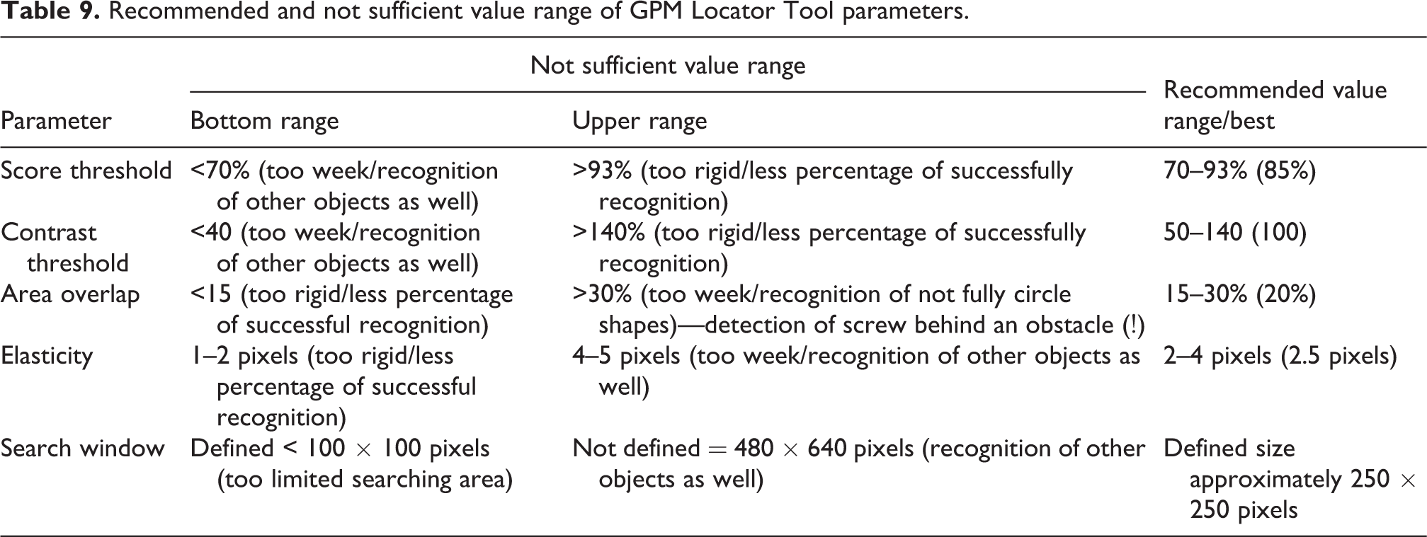
We defined the rectangular Search Window with the size of approximately 296 × 305 pixels. The preparing phase and experimental results are shown in Figure 16 and Table 9.

Reducing the searched area via Search Window tool and examples for NOK and OK results.
Recommended and not sufficient value range of GPM Locator Tool parameters.
Range of horizontal and vertical seat adjustment
Other experiments prove very high influence of original screw position and range of its possible locations (Figures 17 and 18). This relation is caused by quite high light changings in the area of possible screw positions (see Figures 17 to 20).
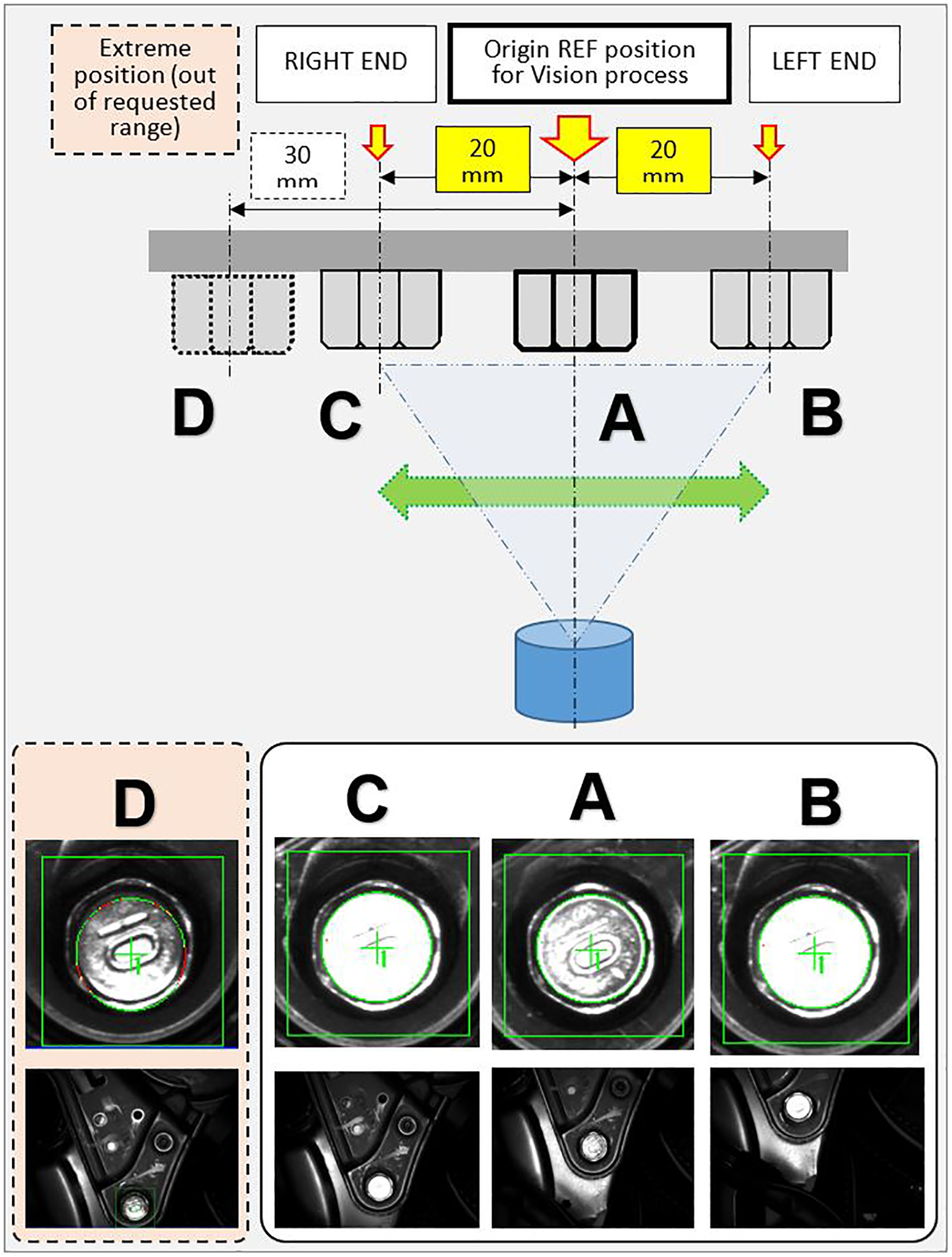
Changing quality of recognized pattern according to offset from reference (REF) position.

The range of vertical and horizontal seat adjustment.

Influence of the seat adjustment range on pattern detection quality—camera snapshots, time-lapse during the seat adjustment motion.

Camera output in different position/coordinates (offset from REF position).
The random unsuccessful recognition of screw 3 on RH seat during the testing phase was identified. We modified the program and vision system setup that in case of negative scan result (system repeating the scan up to 20 times and then send negative result), the control system shifts the robot arm about 10 mm to the side in X-axis (Table 10). This new position can help to reach better optical condition and find the screw position with higher accuracy (see Figure 21). This solution was evaluated after several months run as very successful and efficient.
Normal and shifted (bold; see X-coordinates) “rescan” position P5 for better pattern recognition.

NUT: code for robot specific configuration.

Original position P5 (X: −35), shifted position P5 (X: −43).
Comparison of normal light and IR light source
As it was mentioned above about camera and lightning, two light sources, the red light and IR light, were tested (Figures 22 and 23). The results look not so far each other. A bit better results (more homogenous) were obtained by IR light source, for which we decided in final solution.
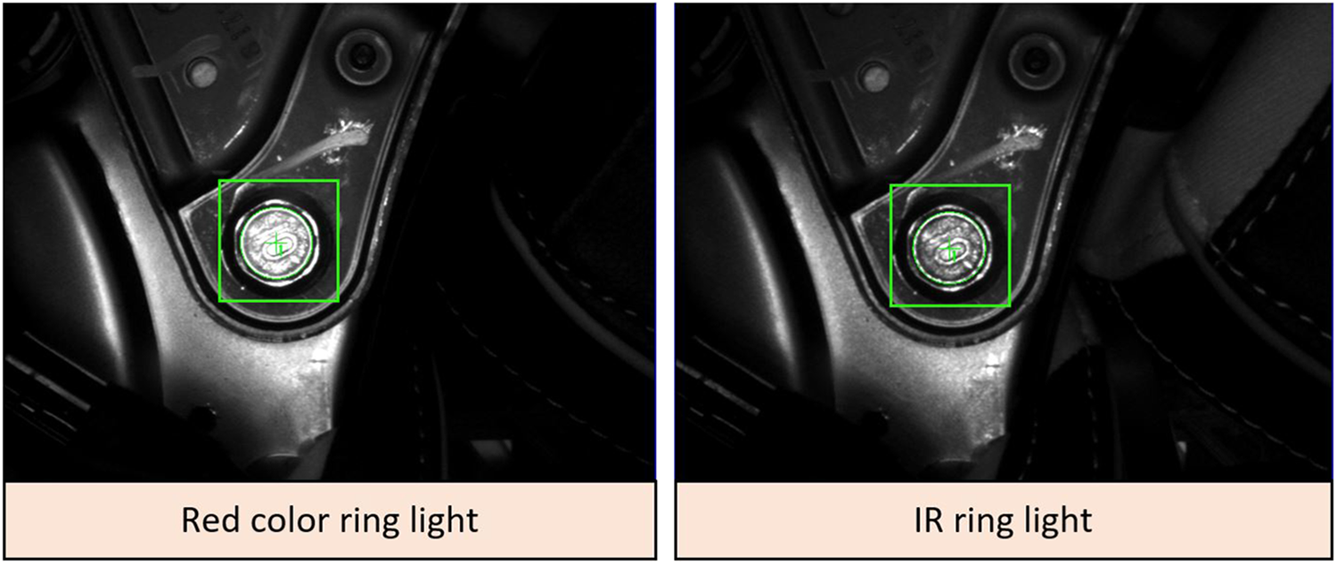
Results comparison between images obtained from standard red color ring light (left) and IR ring light. IR: infrared.
Experimental verification.
Conclusions and future work
Most of the large manufacturing companies, mainly from automotive industry, utilize integration of several systems into automated production lines. The different production facilities such as machine tools and industrial robots equipped with conveyors, pneumatic actuators, or vison systems can be considered as the core features of industrial automation. Utilizing more systems to work as one integrated system including quality control may be the solution to create quality product, increasing productivity and labor cost that result in company’s long-term growth, and customer satisfaction. 36
Due to the ever-increasing variable nature of the production process caused by the increasing customization level of the products, systems enabling the adaptability of production facilities are gaining importance. 35 Under these variable conditions, the vision identification of products, concretely the so-called MV systems or VGR systems, represents strong tools for robotics 15,43 and starting to play a very significant role. However, in spite of their indisputable abilities, the resulting efficiency and successful application of the whole system depends on the quality of technical equipment, their mutual combination, and working condition, but above all on the quality of engineering work (knowledge and skills of the programmer). 44
We presented the case study about the development process and performance analysis of assembly system based on industrial robot FANUC M-20iA/20M with integrated iRVision system for screwing application in automotive industry in this article. The key feature of vision system is the designed robust and optimized recognition method obtained via detailed analysis of its setup and finding the best configuration of the whole system. The contribution of the presented system can be above all improved accuracy and efficiency. Unfortunately, due to the customer restriction, it is not possible to publish the real data from production statistics, to demonstrate the real influence of inaccuracies during the design process, to demonstrate the gradual “step-by-step” refinement, and to demonstrate the final influence of all changings on the final quality and efficiency of designed system. However, at the end of upgrade process, we reached the point where the total number of screwing operations with NOK results is less than required number, and it is about six single negative results per day (less than 0.1% NOK results; total process efficiency is higher than 99.9%). These NOK results are solved by next human operator.
The comparison before/after:
Before—simple bolting work using system tool (1 worker/shift, total three workers);
After—auto bolting using vision system; total 4 screws, location verification by vision reduce workers (1 worker/shift, total three workers); The skills of the engineering staff seem to be a crucial for final success, what was proved also in our experimental test.
The functionality of designed system was tested for approximately 2 years production run. During that period, the functionality of whole system and the functionality of each component were tested. First year was mainly focused on collecting as much as possible practical experiences and data about its behavior and mainly how the system can work under wide variety of conditions—light conditions, type of run, seat type (manual/power, etc.), changing of human operators in working processes ordered before the bolting station, and so on. We have seen that some of our predictions were not met on both sides, as the main problem appears the changing of the light conditions. In general, it can be considered as “the worst enemy” of sensitive VGR system. The light conditions were changed not only during the different part of the day, but even harder during the different season of the year due to the sun trajectory with respect to the windows position in the factory main production hall (unfortunately, the customer doesn’t allow higher percentage of shadows or covering the bolting station). Another expectation that was not met was on customer definition of the basic requirements, mainly cycle time parameter. It was analyzed that in case when the takt time of the production line was increased due to the previous undesirable interruption of the production (production line stopped regarding missing components, unplanned service work in some stations, or the robot needed to do repeating scanning several times per day), the robot wasn’t able to increase its motion and bolting process itself and became a bottleneck of one assembly line segment. They finally redefine the original requirements on robot cycle time, changed from 35 s to less than 25 s (time START/STOP robot) or 45–34 s total cycle time of whole bolting station (time between two seats entering), respectively, what means the necessity to reach about 70% of projected cycle time. The application was tested in automatic regime when the recliner bolting station was able to reach the final cycle time of the robot at the level 21.3 s. So we can conclude that the problem with bottleneck was successfully solved. The experiments confirm our expectation as well as that the successful solution needed precise programming, setup, and exactly to know what is necessary to do.
Furthermore, on the experimental work basis, we can conclude that the successful application need precise analysis of each robotized workplace component, their behavior and interaction, and setup procedure, where all necessary parameters of VGR system are defined. The experimental work proves that:
in cases, the workcell can’t be covered by any shadows and covering, the negative effect of the sunlight can be reduced via study of sun trajectory regarding the windows on walls/roof during whole year and at any part of the day;
The IR light source (SmartView RL-100IR50), combined with proper filters (in our case light red bandpass filter BP635-27 and linear polarizer PR032-27), can improve the detection about 10–20% (red light RL-100R60 was tested as well);
detailed analysis of object motion range within camera FOV and finding the optimal scanning position for pattern recognition seems to be the key element in such systems, which can dramatically reduce later development time and costs;
for similar group of objects (screwheads), the better image results can be reached when optical axis of the camera is offset from screw axis. The screwhead reflections have significant influence positive/negative on detection quality;
The setup procedure of VGR has significant influence on detection reliability, efficiency, and robustness. For similar applications, recommended values are ST = 70–93%, CT = 50–140, AO = 15–30%, E = 2.5 pixels, and reducing the searching area by Search Window function.
Finally, this article can help to other researchers to develop their own solutions for VGR assembly systems and avoid mistakes. We plan more detailed study of whole recliner workcell and its continuous improvement for the future work.
Footnotes
Acknowledgements
The authors would like to thank companies AI engineers crowd, s.r.o., and Hyundai Transys Slovakia, s.r.o., both located in Slovak Republic for helping with practical implementation and experimental verification.
Declaration of conflicting interests
The author(s) declared no potential conflicts of interest with respect to the research, authorship, and/or publication of this article.
Funding
The authors disclosed receipt of the following financial support for the research, authorship, and publication of this article: This work is partially supported by the project APVV-16-0283: “Research and development of multi-criteria diagnosis of production machinery and equipment based on the implementation of artificial intelligence methods” and by grant agency VEGA, project No. 1/0073/19.