
Abstract
In recent years, the environmental perception technology for robotic system has attracted a lot of attention from researchers, but only a little of studies on environmental perception technology are focused on the space underground. Meanwhile, in the field of mobile robotic systems, with the development of research on underground emergency hedging and buried targets’ high-resolution fault imaging, more and more attention has also been paid to underground environmental detection and perception. This article proposes a ground-penetrating radar-based underground environmental perception radar (UEPR) for mobile robotic system indoors. The underground environmental perception radar can achieve noncontact and real-time perception, which helps people detect buried targets and get the image of targets more conveniently and precisely. Major contributions of this work are threefold. Firstly, a stepped frequency continuous wave modulation and demodulation scheme is proposed; secondly, a switch device for a six-channel antenna array is designed and contributed; thirdly, based on a linear antenna array and a signal processing platform, the underground environmental perception radar is supposed to achieve three-dimensional imaging in underground space indoors with its low power consumption. For the experiment of three-dimensional imaging on the copper box and underground environment indoors, the process of imaging is successful, although the size of them is a little bigger than the real size. In addition, the comparison experiment shows that the resolution of underground environmental perception radar system is similar with that of sound wave methods, and the working range of underground environmental perception radar system is deeper than the others. It can be concluded that the underground environmental perception radar can detect the copper box underground and perceive something special within 1.5 m depth.
Keywords
Introduction
In recent years, environmental perception technology for robotic system has attracted a lot of attention from researchers, and most of the studies on it are focused on the space above ground. With the development of computer science, there are more and more environmental perception sensors developed for robotics and artificial intelligence fields, including radio frequency identification (RFID) with its sensors networks, 1,2 lidar sensors, 3 –7 red-green-blue-depth (RGB-D) camera, 8,9 millimeter radar, 3,10 and so on. In addition, the related perception technology above can be classified into two main categories: the one is vision based and the other one is sensor fusion based.
In vision-based technologies, the camera is a powerful sensor for capturing the images in robot vision and building the map for environments. 11 Recently, color-depth cameras have been widely used in robotic system for the applications of environmental perception, such as pose estimation, 9 detection and tracking of humans, 12 autonomous navigation, 13 and simultaneous localization and mapping (SLAM). 8 Compared with the other cameras, a single color-depth camera is able to produce a transformation matrix with an absolute scale because of its additional depth information, 8,14,15 which helps robots achieve higher sensing accuracy with lower system cost. However, the fact that cameras are highly affected by lighting conditions makes those optical sensors unsuitable to be used in dark environment. In sensor fusion-based technologies, a majority of recent published works on environmental perception for robots use sensor fusion-based technologies to achieve path planning, 11,16 driving automation, 17 mobile robot’s navigation, 2,18 and robust obstacle detection and classification. 5 Moreover, for different applications, the strategies of sensor fusion are also different. For example, the fusion of wireless sensor network and RFID tags is often used in indoor environment because of its low-cost hardware and relatively reliable services, 1,2,18 but its principle limits the application of environmental perception in outdoor. As a fact, the vision- and radar-based sensor fusion has been discussed mostly for outdoor environmental perception, especially for in-road applications, 19 –21 where radar sensors are usually used to provide extra features and help visual sensors to classify the targets.
Meanwhile, with the development of research on underground emergency hedging and buried targets’ fault detection, more and more attention has also been paid to underground environmental detection and perception. However, compared with a variety of detection and perception methods for the space above ground, the technical means are limited for underground environmental detection and perception. Until now, there have been three effective ways, including a way based on electromagnetic technology, Internet of things (IoTs) technology, and seismic (Rayleigh) waves.
For underground detection, the electromagnetic-based technology now is the most effective way to achieve noncontact detection for the features underground. As a typical equipment for underground detection, ground-penetrating radar (GPR) has been widely used in a lot of fields. For example, early on, the GPR is usually used to detect targets underground, like pipeline networks and antipersonal land mine. 22 In the last decades, it is also confirmed that the moisture content of wood sample and surface soil moisture can both be measured using a GPR-based sensor. 23,24 In addition, with the high performance in the field of noncontact detection for the features underground, the GPR system has also been used in archeology study, such as identifying pavement construction periods of Valencian Silos in the 16th century. 10
For achieving underground perception, there have been three methods proposed in recent years. The first method is based on IoT technology, which is a core technology to specialize in underground model building for the mine IoT. 25 However, in IoT technology, a sensor network must be constructed underground in advanced, which means that the underground environmental perception based on IoT technology cannot be used in real-time and noncontact working scene. The second method is based on seismic (Rayleigh) waves, which is designed to achieve buried-object noncontact detection and imaging and to detect deeper targets. 26 Similarly, there are also some other studies on detecting buried relics and ruins at shallow depths using sound chirp wave. 27,28 The third method is based on underground environmental perception radar (UEPR) system, which combines radar system and image processing technology to achieve real-time and noncontact underground environmental perception. For example, in order to interpret UEPR B-scan images and estimate buried pipes, an UEPR imaging and explanation method has been proposed. 29 The method perceives environment using the performance of electromagnetic wave propagation in soil or cement.
Compared with the other two methods, the UEPR method has some irreplaceable advantages. With real-time and noncontact detection, this method can also achieve high imaging resolution and higher detection speed. Besides, the GPR-based UEPR method can achieve deep detection depth without losing the other methods. Therefore, the advantages above promote the application of GPR-based UEPR method in the field of mobile robotic system indoors. Recently, the technology related to ultra-wideband (UWB) radar has been introduced for some applications indoors, like human detection and tracking, 30 pipeline noncontact detection, and indoor electrical wiring imaging. With irreplaceable advantages of the choosing method, this research can improve the detection speed and imaging resolution of applications above.
As a result, for buried targets’ noncontact detection and real-time imaging indoors, a GPR-based UEPR system, which can be loaded on a mobile robotic system indoors, is proposed in this article. Based on a linear antenna array and a signal processing platform, the UEPR can be loaded on indoor robotic system and can achieve three-dimensional (3-D) imaging in underground space indoors. In addition to improving imaging resolution and detection speed, the 3-D imaging function of UEPR system can greatly improve the intuitiveness of detection results. Major contributions of this work are threefold. Firstly, in order to sample the UWB signals using an A/D conversion with relatively low sampling rate, we propose a stepped frequency continuous wave (SFCW) modulation and demodulation scheme. Then, we design a switch device for a six-channel antenna array to achieve the linear scan of signal channels. At last, an experimental study is performed to confirm that UEPR can be loaded on indoor robotic system with its low power consumption and can achieve 3-D imaging in underground space indoors.
Theoretical analysis on GPR-based UEPR
The UEPR system aims at achieving 3-D imaging for the target underground. Concretely, the whole working process of UEPR system basically consists of the following parts: The part of hardware is shown in Figure 1, where the structure of SFCW modulation and demodulation with switch matrix component and antenna array is elaborated. In this part, the modulated and received SFCW, which consist of 1-MHz local oscillator (LO) signal and linear sweeping baseband signal, both sweep from 300 MHz to 720 MHz, with 6-MHz stepped frequency. On the other hand, the part of software is shown in Figure 2, where the whole 3-D-imaging process is elaborated. In this part, the compressed echo signals sampled by analog-to-digital converter (ADC) are decompressed and imaged according to the channels that they belong to.

The structure of SFCW modulation and demodulation with switch matrix component and antenna array. SFCW: stepped frequency continuous wave.

The processing of 3-D-imaging. 3-D: three-dimensional.
In this section, in order to elaborate the whole working process of UEPR system, the basic theory of the system is supposed to introduce from the following three aspects.
Analysis on GPR-based perception in underground space
To achieve GPR-based perception in the space underground, we firstly simulate the process of electromagnetic propagation using gprMax with the method of finite-difference time-domain (FDTD). The basic information of FDTD for GPR modeling can be found in the literature. 31 –33 Then, we extract the characteristic signals of every channel and achieve 3-D imaging for the target underground.
The electromagnetic propagations, on a macroscopic scale, can be described by the following Maxwell’s equations, which express the relations between the fundamental electromagnetic field quantities and the dependence on their sources using first-order partial differential equations.


where t is time (s) and qv is the volume electric charge density. To simulate the response of GPR-based system from a set of targets, Maxwell’s equations should be solved subject to the initial conditions and the geometry problems. As a result, the FDTD, a numerical solution of Maxwell’ equations, is presented to discretize the space and time continua. In addition, the building block of this discretized grid in this simulation is Yee cell, which is shown in Figure 3, where δx, δy, and δz define the discretization spatial size, and δt temporal step. In addition, the values of δx, δy, δz, and δt should be subject to the following relation rather than assigned independently.

where vp is the velocity of electromagnetic wave in different dielectrics.

3-D FDTD Yee cell. 3-D: three-dimensional; FDTD: finite-difference time-domain.
According to the analysis above, we set the value of parameters in this simulation, which are listed in Table 1. Then, as shown in Figure 4, we build a 3-D environment based on the assignment in Table 1, with an underground space in red and a mental target in blue. Then we take the measurements five times in different path using the antenna couple in Figure 4, and the simulated results in different path, which is called B-scan, are shown in Figure 5. It is obvious that both the amplitude and shape of radar echo in every path are different, and the amplitude of radar echo in the middle path is the largest. Moreover, the 3-D radar echo shape without direct-coupled wave can be calculated with these five B-scan data.
Parameters of the UEPR system.

UEPR: underground environmental perception radar.

The simulated 3-D environment with a red underground space, a blue mental target and a couple of antennas. 3-D: three-dimensional

The simulated results in different paths.
Study on SFCW modulation and demodulation
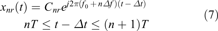
The dielectric consists of bricks and cement in underground environment indoors. To achieve high resolution and large detection range, it is necessary to modulate and transmit UWB SFCW signals to the ground. On the other hand, depending on the sampling rate of ADC and digital-to-analog converter (DAC), in order to achieve modulating and demodulating the UWB signals successfully, we decide to use double direct digital synthesizer circuit with short frequency switching time to produce stepped frequency signals, where one is used to produce baseband signal and the other one is used to produce LO signal. The modulated transmitted signals can be formulated as follows

where f
0 is the frequency of LO signal,
where

Then, we make

where

As shown in equations (9) and (10), Xn
is a function of time t, but every frequency group of it can also be a sampled echo wave in frequency domain. It means that Xn
is also a function of

If the target is at rest, the velocity v of it will be 0, and Hl can be formulated as
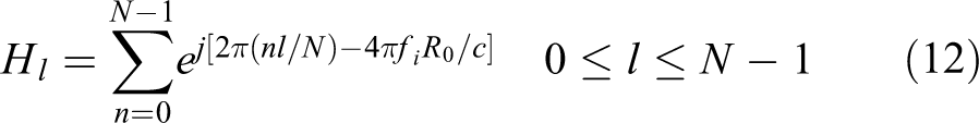
where l is the time of propagation and R 0 is the distance between antennas and a target.
Based on theory above, we measure the transmitted and collected distance profile Hl using UEPR system, and the results are shown in Figure 6, in which the blue curve is the transmitted distance profile and the red curve is the collected distance profile. As is shown, it seems that the radar transmits a Gaussian pulse after IFFT, although the radar system is designed as continuous wave. However, compared with the pulse radar, SFCW radar is easier to achieve high resolution and large detection range because its bandwidth can be much wider than pulse radar.

We measure the transmitted distance profile in blue and the collected distance profile in red using UEPR system. UEPR: underground environmental perception radar.
Study on switch strategy of signal channels
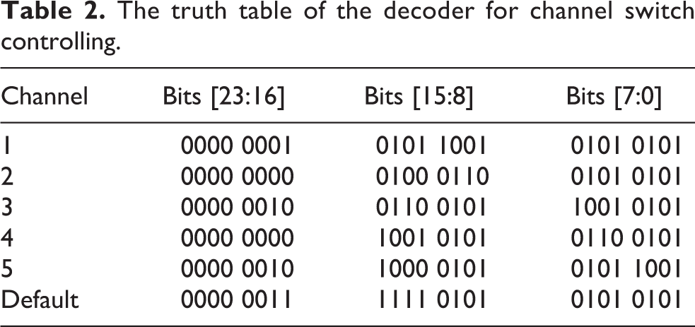
To achieve antenna array linear scan with a set of signal chain, we design an RF switch matrix using a group of component combination including two single-pole-six-throw switches and six single-pole-two-throw switches. The topological structure of the switch matrix is shown in Figure 7, where the five colors represent five different channels. More concretely, the signal chain starts with Tx-SW1-SW2-Rx in red and sweeps to Tx-SW5-SW6-Rx in blue, which creates five channels of data. Every channel has its unique number for accurately channel switch controlling. For example, when channel 1 (Tx-SW1-SW2-Rx) is enabled, port IN1 is connected with port O1 in Tx model and Rx model, both of which belong to single-pole-six-throw switches; meanwhile, port P1 is connected with P3 in SW1 model, and port P3 is connected with P2 in SW2 model, where both of them belong to single-pole-two-throw switches. Every model has its own control instruction. To perform this operation, we design a decoder to translate the number of channels to control instructions using field programmable gate array (FPGA). The truth table of the decoder is shown in Table 2. As is shown, the selected bits [11:0] are programmed to configure the signal path of single-pole-two-throw switches, and the selected bits [17:12] are programmed to configure the signal path of single-pole-six-throw switches. The other bits are reserved for the extendibility of switch matrix.

The topological structure of the switch matrix where the five colors represent five different channels.
The truth table of the decoder for channel switch controlling.
In addition, every channel would be held for 14.1 µs, if the radar starts working. The holding time of every channel consists of three parts: controlling signal rising/falling time, RF signal ON/OFF time, and SFCW pulse holding time. For switch matrix, the time of controlling signal inversion is around 40 ns and the time of RF path ON/OFF is around 70 ns, and the SFCW pulse holding time is around 14 µs. As a result, the time of a five-channel scanning is 70.5 µs and the movement of robotic system is too small to consider about. It means that the robotic system can move with high velocity when it is working.
Experiment and discussion
In this section, we make an experimental platform which can be loaded on robotic system indoors, and the parameters of this platform are listed in Table 3. As is shown, its small size determines that the system is able to be loaded on mobile robot platform and work in a narrow space. Then, we take the three experiments: The first one, as shown in Figure 8(a), is the detection for a copper box; the second one, as shown in Figure 9(a), is the detection for realistic underground space indoors; and the last one is a comparison experiment in different depth. The platform is shown in Figure 10, where there are six antennas on the bottom and a set of signal processing function on the top.
Parameters of the UEPR system.

UEPR: underground environmental perception radar; SFCW: stepped frequency continuous wave.

(a) The experimental environment of copper box detection. (b) The collected signals of five channels before and after enhanced. (c) Seven layers of underground environment in copper box detection.

(a) The experimental environment of a realistic underground space indoors. (b) The collected signals of five channels before and after enhanced. (c) Seven layers of underground environment in experiment of the detection for realistic underground space indoors.

The experimental platform for robotic system.
For the first experiment, both the detection area and the target are marked in red, where the big one is the area, and the small one is the target. We scan the area and collect the echo signals using the UEPR platform. Then, there are five B-scan pictures produced with direct-coupled wave only. To extract the characteristic echo wave, we make some improvements for a histogram equalization algorithm and enhance the B-scan pictures using the improved algorithm. Figure 8(b) shows the results of five channels before and after enhancement. We replace these five enhanced pictures as the arrow, as shown in Figure 8(a), where the number of channels can also be a sign of length. After sampling in different depth, as is shown in Figure 8(c), the characteristic signals of the target in seven layers are collected. As is marked in red lines, the image of target is similar to a rectangle in layers 3 and 4. However, in layers 5–7, the signal amplitude is falling, and the attenuation of signals in channel 2 is faster than that of other channels. At last, we extract the characteristic point by setting a threshold, and the 3-D image of copper box is shown in Figure 11, where the box is marked in a blue rectangle.

The 3-D image of the copper box. 3-D: three-dimensional.
To detect realistic underground space indoors, for the second environment, without any special target, the detection area is also marked in red. We scan the area and collect the echo signals using the UEPR platform. Then, there are also five B-scan pictures produced with direct-coupled wave only. After the enhancement, the characteristic echo wave is extracted with the help of improved algorithm. Figure 9(b) shows the results of five channels before and after enhancement. The same as the first experiment, we replace these five enhanced pictures as the arrow, as shown in Figure 9(a), where the number of channels can also be a sign of length. After sampling in different depth, as shown in Figure 9(c), the characteristic signals of the target in seven layers are collected. As is marked in red lines, the extracted signals in layers 5–7 are obviously stronger than those in layers 2–4. In addition, the shape of extracted signal is similar to pipelines. Then, the 3-D imaging in Figure 12 shows that there is something special in the depth of 0.9 m.

The 3-D image of the environment underground. 3-D: three-dimensional.
On the basis of experimental results above, in the last experiment, the resolution of the UEPR system is analyzed. First of all, we improve the experimental platform to meet the requirements of this comparison experiment. Specifically, as shown in Figure 13, there are six metal balls with 10 cm radius, which are spherical perfect electric conductors in the simulation, put into a wood box full of solid. The six mental balls are divided into three couples, and the distance between every couple of balls and the depth of them are both adjustable. In this article, the values of depth are set as 0.3, 0.9, and 1.5 m, and the distance between every couple of balls in every depth is set as 0.1, 0.2, and 0.3. In addition, the distance between two couples is 0.5 m. Then, we scan the box using the UEPR system. If the distance between two balls is smaller than the resolution of system, UEPR system will just show one target in the image; if the distance between two balls is bigger than the resolution of system, UEPR system will show two targets in the image. On the basis of imaging results, the UEPR resolution in different depth can be detected. As shown in Figure 14, the targets are marked in red rectangles. It can be concluded that as the depth of targets increases, the UEPR resolution becomes lower and lower. For example, the two balls 30 cm apart can be identified as two separated targets in a depth of 0.9 m underground but identified as one target in a depth of 1.5 m underground.

The distribution of six mental balls.

The image in different depth.
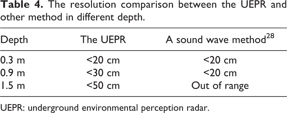
Combining the above experimental results, the resolution of UEPR in different depth is shown in Table 4. Meanwhile, we compare the effect of UEPR with two ultrasound imaging methods. 26,28 Firstly, the UEPR can achieve 3-D imaging, which two ultrasound imaging methods cannot do. Secondly, according to the experimental results, although the resolution of the methods is similar, the UEPR detection range, which is from 0.3 m to 2.1 m, is larger than ultrasound imaging methods. However, compared with Bulletti’s method, 26 UEPR cannot identify the material of the targets.
The resolution comparison between the UEPR and other method in different depth.
UEPR: underground environmental perception radar.
In a word, the GPR-based UEPR system is able to achieve underground environmental perception indoors in a narrow working space. In addition, the comparison experiment shows that the resolution of UEPR system is similar with that of sound wave methods, and the working range of UEPR system is deeper than the others. However, in these two 3-D imaging, the size of imaging target is a little bigger than the size of real target. This problem is supposed to be improved in future research.
Conclusion
The environmental perception technology for robotic system has attracted a lot of attention from researchers recently, but only a little of studies on environmental perception technology are focused on the space underground. In this article, a GPR-based UEPR for mobile robotic system indoors is proposed. Major contributions of this work include three functions: Firstly, an SFCW modulation and demodulation scheme is proposed; secondly, a switch device for a six-channel antenna array is designed and contributed; thirdly, based on a linear antenna array and a signal processing platform, the UEPR is supposed to achieve 3-D imaging in underground space indoors with its low power consumption. For the experiment of 3-D imaging on the copper box and underground environment indoors, although the size of them is a little bigger than the real size, the process of imaging is successful. In addition, the comparison experiment shows that the resolution of UEPR system is similar with that of sound wave methods, and the working range of UEPR system is deeper than the others. In the end, the simulation and experimental results show that the UEPR can detect the copper box underground and perceive something special within 1.5 m depth.
Footnotes
Declaration of conflicting interests
The author(s) declared no potential conflicts of interest with respect to the research, authorship, and/or publication of this article.
Funding
The author(s) disclosed receipt of the following financial support for the research, authorship, and/or publication of this article: This work was supported by the National Natural Science Foundation of China [61673128, 61573117, and 41627801] and the Natural Science Foundation of Heilongjiang Province [F2015031].