
Abstract
A high-precision prescribed-time guidance law is developed for a quadrotor to accomplish precise path following at predesigned time T. Firstly, a new control structure is proposed for a quadrotor to perform fixed-velocity back-to-turn flying mode by introducing four controllers, which can realize a non-sideslip and bank-to-turn flight scheme just like a fixed-wing unmanned aerial vehicle. Then, prescribed-time guidance law is presented based on fixed-velocity back-to-turn flying mode via combining sliding mode control with a compensation function
Introduction
Quadrotors have numerous potential applications no matter for military or civil use. They present many advantages compared with fixed-wing unmanned aerial vehicle (UAV) including high maneuverability, the capability to hover, vertical takeoff, and landing in limited spaces. 1,2 In recent years, the missions of quadrotor are becoming more complex such as close range surveillance, detection, and commercial package management. 3,4 All the missions put forward a requirement of an accurate path following method. In addition, to execute time critical mission reliably for quadrotor, such as simultaneous arrival scenario, cooperative surveillance, cooperative target tracking, and spatial-temporal cooperative formation flying, 5,6 it is necessary to investigate a novel path following method, which can drive quadrotor to achieve the desired path at pre-designed time exactly.
The existing guidance laws of quadrotor achieve position control by tracking a set of given waypoints or time-varying target point. 7,8 However, such flying mode cannot maintain a constant flight speed, which is proportional to the distance between the quadrotor and the target point. In addition, it cannot achieve precise smooth turn with a constant speed. To improve the conventional flying mode, a new control structure is developed for quadrotor in this article to perform fixed-velocity back-to-turn flying mode, which can realize path following at any given velocity profile. Four controllers are introduced for the control structure, namely course hold controller, longitudinal controller, lateral controller, and height controller. By means of applying the novel flying mode, quadrotor not only has strong maneuverability but also can perform a non-sideslip and bank-to-turn flight scheme just like a fixed-wing UAV. Based on it, path following guidance law of fixed-wing UAV can be effectively applied to quadrotor.
There have been many effective methods of path following developed for fixed-wing UAV. An approach named “vector field” is proposed by Miao and Fang, 9 the purpose of which is not to make vehicle pursue a moving point but to get on the desired path at given velocity. An adaptive optimal path following is developed by Ratnoo et al. 10 It regards the path following of a vehicle as a general infinite-horizon nonlinear problem which is solved by combining a linear quadratic regulator with an adaptive gain. A nonlinear guidance law motivated by proportional navigation of missile is introduced by Park et al. 11 and Curry et al., 12 which contains an element of anticipatory control to guarantee tight tracking. Sujit et al. performs simulations of some existing path following methods and compares the control efforts and tracking errors of them. 13 The foregoing literature are all confirmed to be effective. However, they cannot achieve path following at predesigned time exactly and the tracking accuracies of them are not high enough.
To improve the conventional methods, sliding mode control is recommended for designing path following guidance law, due to its advantages of high precision and robustness. Sliding mode control includes reaching phase and sliding phase. Reaching phase drives system to sliding surface, while sliding phase makes state error slide to origin. There are several forms of sliding surfaces, like linear sliding surface, integral sliding surface, terminal sliding surface, fixed-time sliding surface, and so on.
14
Linear sliding surface and integral sliding surface could only realize exponential convergence. Terminal sliding surface can achieve system stabilization in finite time, but the convergence time grows along with the increase of initial condition. The fixed-time sliding surface proposed by Polyakov can overcome this disadvantage.
15
However, since the fixed convergence time obtained by theoretical derivation is too conservative compared with actual convergence time, it is difficult to carry out the actual design and parameter adjustment based on theoretical results.
16
Therefore, a prescribed-time sliding surface is developed based on a compensation function
In summary, the contributions of this article are given as follows:
A novel control structure is designed for quadrotor to realize fixed-velocity back-to-turn flying mode. Based on it, quadrotor can perform a non-sideslip and bank-to-turn flight scheme just like a fixed-wing UAV.
A PTGL is proposed for quadrotor to realize path following at prescribed time exactly. Meanwhile, higher tracking precision can be ensured compared with the conventional path following guidance law.
An outline of the article is as follows: The second section presents a dynamic model of quadrotor. The third section introduces the four controllers used to make quadrotor realize fixed-velocity back-to-turn flying mode. The fourth section proposes the PTGL based on an accurate model and presents a strict proof for prescribed-time convergence. In the fifth section, simulations are performed to show effectiveness and superiority of the method proposed.
Quadrotor modeling
In this section, the dynamic model of quadrotor is developed. 17,18 The quadrotor structure is presented in Figure 1, with the definition of inertial frame, body frame, and positive direction of rotor rotation.

The definition of (a) quadrotor model and (b) coordinate frames.
The rotation matrix from inertial frame (I) to body frame (B) is modeled following Z-Y-X order. To transform from I to B, firstly we rotate around zI
by yaw angle ψ, then rotate around the intermediate

in which

in which

where
The forces acting on quadrotor are gravity G and aerodynamic force produced by four rotors which is denoted by Ta . The dynamic equations of vehicle are as follows


where m is vehicle mass. Notations
The relationship between forces, torques, and angular velocity ω of each rotor is given below

in which l is the distance between the barycenter of quadrotor and the rotor, while k and b express lift and drag constant, respectively.
In addition, resultant velocity V and course angle χ are defined as

Fixed-velocity back-to-turn flying mode
To realize fixed-velocity back-to-turn flying mode, a new control structure is proposed in this section, composing of four controllers. By means of applying the novel control structure, quadrotor can perform a non-sideslip and bank-to-turn flight scheme just like a fixed-wing UAV.
Firstly, for the sake of achieving non-sideslip flight, course angle χ is selected as desired yaw angle. Course hold controller is used to make yaw angle ψ reach course angle χ, so as to guarantee the plane determined by xB axis and the resultant velocity vector is coincident with vertical plane. The course hold controller loop is shown in Figure 2 in which inner controller is defined applying proportional–derivative (PD) control algorithm for practical engineering application

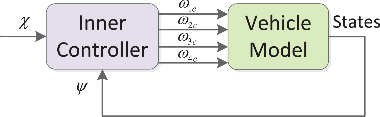
Course hold controller loop.
The purpose of longitudinal controller is to make quadrotor achieve the desired velocity Vd
by pitching to desired pitch angle


Longitudinal controller loop.
Outer controller is given using proportional–integral–derivative (PID) algorithm as follows
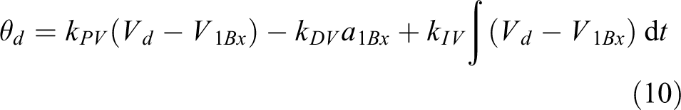
where
The purpose of lateral controller is to make lateral acceleration


Lateral controller loop.
Outer controller is given using PI algorithm as follows

Height controller is used to make quadrotor arrive the expected altitude, which can be realized easily by making four rotors speed up or speed down at the same time. Therefore, height command zc can be imported to inner controller directly. The height controller loop is shown in Figure 5 in which inner controller is defined applying PD algorithm


Height controller loop.
Although the above four PID controllers are not able to achieve accurate and perfect tracking control as advanced control theories, they are more convenient for practical engineering application. The disturbance in quadrotor dynamics is mainly reflected in parametric uncertainties, such as mass, moments of inertia, lift constant, drag constant, and so on. The magnitude of the disturbance is generally small, which can be solved effectively by robustness of PID controller. Therefore, there is no need to apply the advanced but complex controllers with stronger robustness, such as
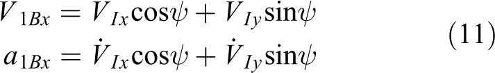
After calculating the four command signals

Based on the new control structure mentioned above, advanced guidance law can be developed for quadrotor to realize high-precision and prescribed-time path following.
In the actual task of path following, desired velocity and desired height are given by the task in advance. To follow the desired path, guidance law designs lateral command acceleration to eliminate cross-track error. Therefore, in the process of performing a path following task, height controller drives quadrotor to the height of path and keeps it. Longitudinal controller adjusts velocity of quadrotor to the desired value and maintains it. Course hold controller is used to make yaw angle ψ reach course angle χ in real time, to avoid the influence of yaw angle ψ on lateral movement. Thus, lateral movement can only be achieved by rolling to track the designed lateral command acceleration, which is realized by lateral controller.
In summary, among the four controllers, height controller and longitudinal controller are independent, and they are less related to the other two controllers. The course hold controller and lateral controller are integrated. They cooperate with each other to realize back-to-turn flying mode for lateral tracking control. The interaction of the four controllers is illustrated in Figure 6.
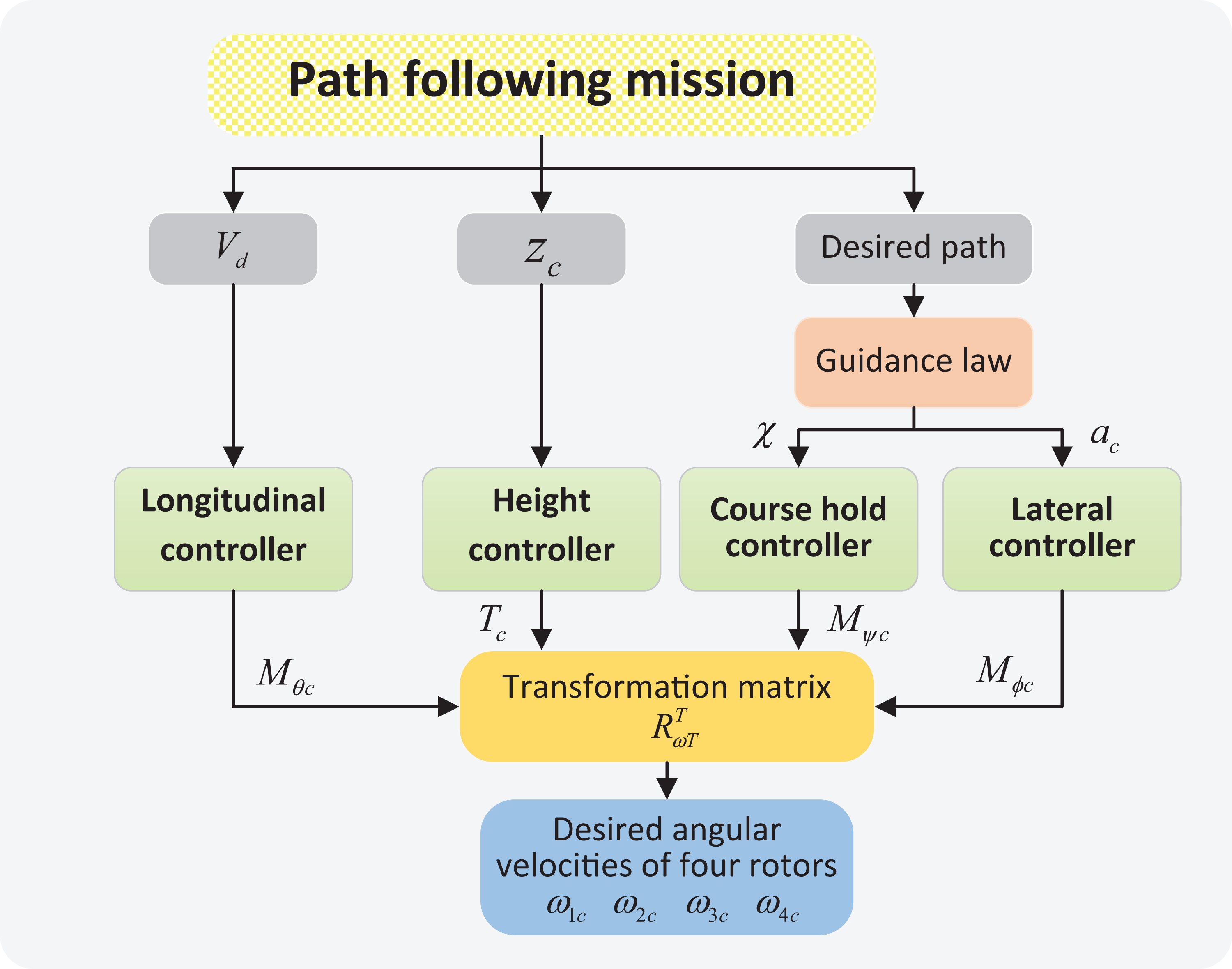
Relationship between four controllers when performing a path following mission.
High-precision PTGL design
In this section, a high-precision PTGL is proposed to decrease cross-track error and realize prescribed-time path following.
In the actual engineering application of path planning for fixed-wing UAV, the real-time characteristics and the small amount of calculation are very important. 19 Therefore, the path planning method based on Dubins path has become an effective and widely used solution, which can realize high-efficient, real-time, and online path planning. 20,21 The Dubins path is a shortest path from the starting point with initial prescribed heading to the final position and heading. 22 The path consists of circular arcs and straight lines, which establishes optimal transitions between different waypoints. 13 Compared with the complicated path, the Dubins path has the shortest length and is easy to implement in engineering. The demonstration of Dubins path is given in Figure 7.

Demonstration of Dubins path.
To ensure the practicality of engineering, many existing path-following schemes are designed based on Dubins path. Considering Dubins path is composed of circular arcs and straight lines, the guidance laws designed by researchers are all divided into two modes: straight line and circular path following modes. 13,20 Therefore, the straight line and circular path-following modes are also designed, respectively, in this article.
The relationship of vehicle position, velocity, and desired linear path in horizontal plane is shown in Figure 8, where d is the cross-track error. Desired course angle


Geometry relationship between quadrotor and desired path in horizontal plane.
Selecting lateral acceleration as control variable:

It should be noted that velocity
Defining

Ratnoo et al. assumes that


Geometry relationship in circular path.
To enhance convergence precision, guidance law is designed for nonlinear system equation (17) based on sliding mode control. In addition, a compensation function p(t) is introduced to realize prescribed-time convergence. Sliding mode variable s is designed as

where c must satisfy Hurwitz condition:

in which

Combining sliding surface equation (20) and exponential reaching law, the PTGL is proposed as follows
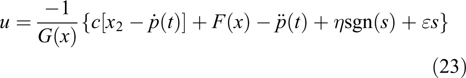
in which η and ε are positive design parameters of reaching law.
The aim of designing function p(t) is to guarantee the errors of state variables converge to zero at prescribed time T. Therefore, p(t) is defined as a piecewise polynomial function

In addition, for the sake of establishing global sliding mode, p(t) should satisfy

To make the second-order derivative of p(t) continuous at given time T, conditions below are essential

Applying conditions (25) and (26) into (24), the following equations can be obtained
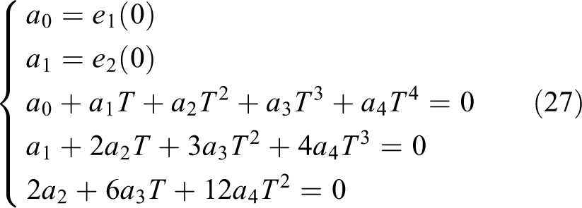
According to equation (27), coefficients are solved as

Theorem 1
The errors of state variables e 1 and e 2 are able to converge to origin at prescribed time T using the PTGL in equation .
Proof
The process of proof is divided into two steps. The first step is used to prove the convergence of sliding mode variable s, while the second one proves the exact convergence of tracking errors e
1 and e
2 at given time T. Step 1: Convergence of traditional sliding mode control is composed of reaching phase and sliding phase. The former is used to drive the system converge to sliding surface, which also means to achieve the convergence of sliding mode variable s. The latter is used to make states e
1 and e
2 converge to zero along the sliding surface. Therefore, the convergence time of sliding mode control also consists of reaching time and sliding time.
Combining the definition of sliding mode variable equation (20) and conditions in equation (25), it can be obtained that initial value of s is satisfied with
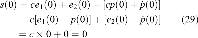
which means that system using PTGL lies in sliding surface from the beginning. Therefore, compared with applying traditional sliding mode control, the system using PTGL does not have initial reaching phase and the convergence of system starts directly from the sliding phase.
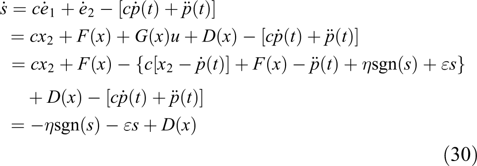
Substituting equations (23) and (20) into equation (18), dynamics of s is satisfied with
A positive Lyapunov function for sliding mode variable s is defined as

If
If Step 2: The following relationship is satisfied according to equation (20)

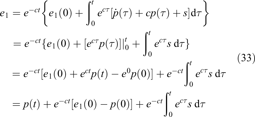
Solving differential equation (32), e 1 can be obtained
If
If
According to the above analysis, the maximum value of divergence for s is
Remark 1
Considering sliding mode variable s is initially equal to zero, system is located on sliding surface at the beginning. Therefore, system can eliminate initial reaching phase, so as to accelerate response speed and enhance robustness.
Remark 2
If compensation function p(t) is defined as zero, the PTGL in equation will degenerate into high-precision guidance law (HPGL) and lose its character of prescribed-time convergence but remain robust and accurate.
Remark 3
In order to restrain the chattering phenomenon in engineering application, a saturation function can be used to replace sign function sgn(s) in equation

in which Δ is a sufficiently small constant.
Remark 4
In the actual path following task, in order to track the desired Dubins path, quadrotor can switch between straight line and circular path-following modes automatically in real time, according to different desired path segments.
Simulation
In this section, a high-fidelity nonlinear 6-degree-of-freedom model of quadrotor is implemented with the proposed control structure and guidance law. The nominal parameters of quadrotor are given in Table 1. 24,25 Three subsections are carried out to verify the effectiveness of method proposed in detail. “Straight line following” section compares HPGL and PTGL in linear path following. “Circular path following” section compares the method in this article with a conventional guidance law in circular path following, so as to highlight the advantages of high precision and prescribed-time convergence. “Complex path following” section verifies the validity of PTGL on a complex path following task.
Parameter table of quadrotor.

The desired ground velocity and height command are
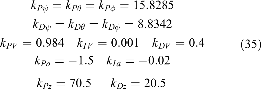
Controllers of quadrotor are designed according to the “Fixed-velocity back-to-turn flying mode” section to realize fixed-velocity back-to-turn flying mode. To suppress the influence of high-frequency noise in practical applications, parameters of PID controllers are adjusted to minimize the value of amplitude–frequency curve in high frequency band. By means of designing appropriate bandwidth, the introduction of high-frequency noise can be avoided. Parameters for four controllers are selected as follows
Remark 5
In order to avoid the accident of quadrotor caused by an excessive attitude angle, the magnitudes of desired angles
Straight line following
In this subsection, two cases of simulation are carried out. Case A utilizes the HPGL without compensation function p(t) as comparative simulation, while Case B applies the PTGL with compensation function to verify its effectiveness.
From a theoretical point of view, cross-track error e
1 can achieve precise convergence effectively. However, in practical applications, tracking error is inevitable due to the effect of sampling step. Therefore, the tracking task can be considered complete when error e
1 is less than
The design parameters of the guidance law are selected as Case A:
It can be seen from Figures 10 and 11 that quadrotor tracks the desired path directly using HPGL and the final cross-track error is almost zero. In this case, t 1 is equal to 72.37 s.
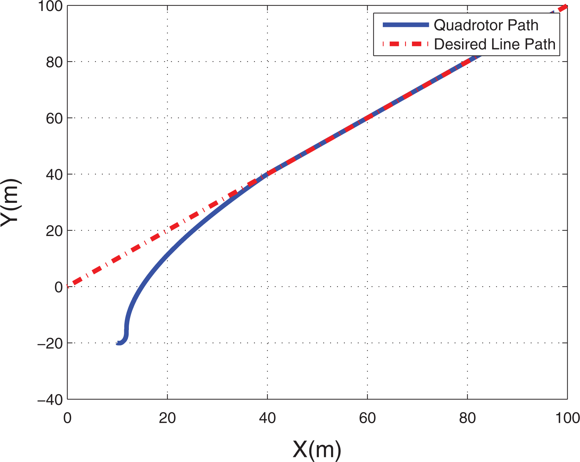
Result of straight line path following using HPGL. HPGL: high-precision guidance law.

Cross-track error of straight line path following using HPGL. HPGL: high-precision guidance law.
Case B: The prescribed time T is set as 120 s for PTGL in this case.
Figure 12 shows that quadrotor does not fly directly to the path like Figure 10, to realize path following at given time. It can be observed from Figure 13 that e
1 and
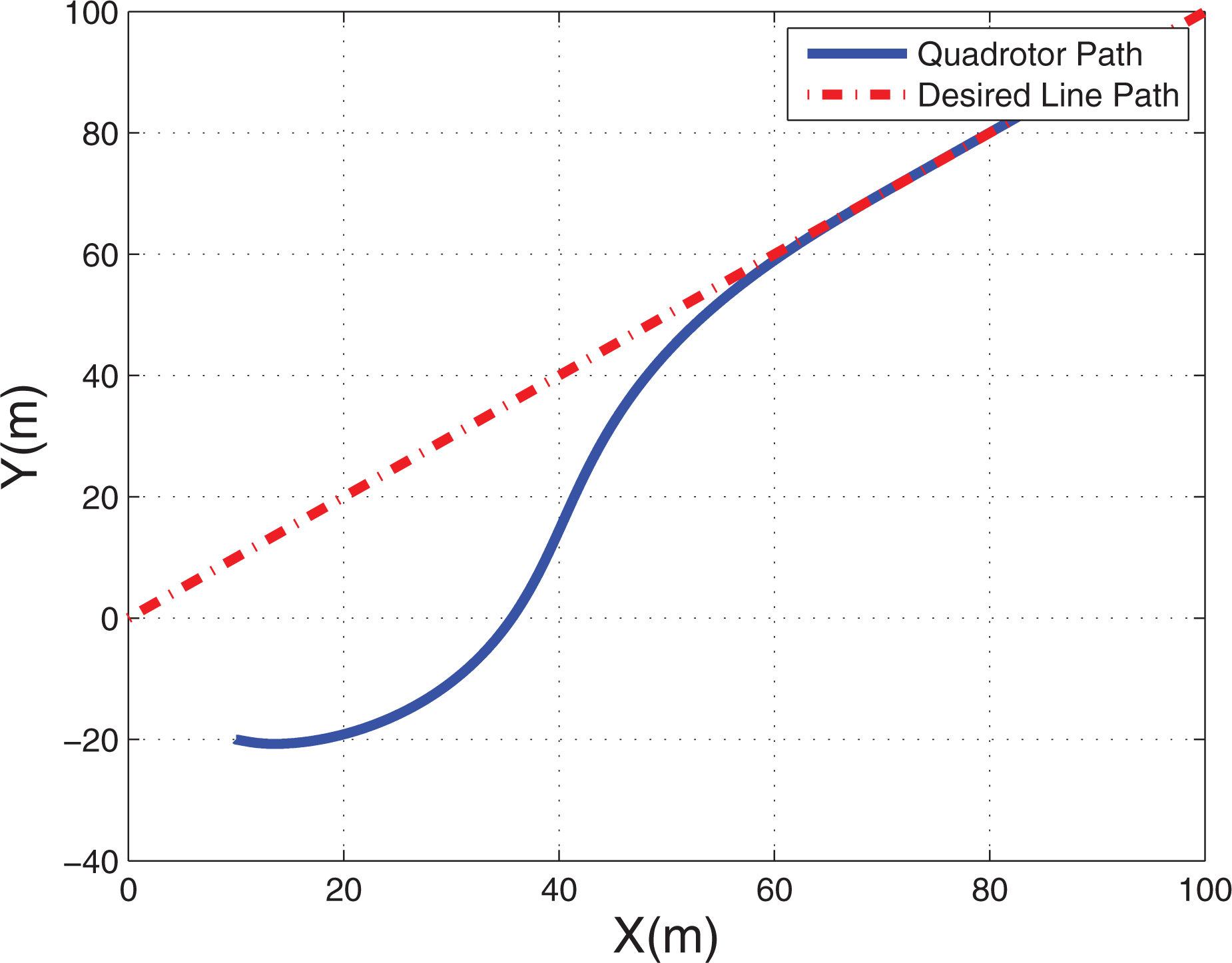
Result of straight line path following using PTGL with T = 120 s. PTGL: prescribed-time guidance law.

(a and b) Cross-track error of straight line path following using PTGL with T = 120 s. PTGL: prescribed-time guidance law.
In Figure 14, tracking performance of course hold controller and longitudinal controller are displayed. It can be seen that yaw angle ψ can track the course angle χ accurately to realize no-sideslip flight under the effect of course hold controller. Longitudinal controller drives the pitch angle θ to reach a stable value quickly, so as to make velocity
(a to c) Tracking performance of course hold controller and longitudinal controller with T = 120 s.

(a to c) Tracking performance of lateral controller and height controller with T = 120 s.
To verify the effectiveness of prescribed-time convergence more comprehensively, two different simulations are performed using PTGL with prescribed time T set as 90 and 130 s.
Figures 16 and 17 show that quadrotor can follow the desired path with convergence time t1 = 90.31 s. Similarly, it can be observed from Figures 18 and 19 that convergence time t 1 is 129.78 s. The two convergence times are all approximately equal to given prescribed times. Therefore, the two simulations demonstrate that PTGL are able to adjust the convergence time freely according to task requirements while ensuring convergence.

Result of straight line path following using PTGL with T = 90 s. PTGL: prescribed-time guidance law.

(a and b) Cross-track error of straight line path following using PTGL with T = 90 s. PTGL: prescribed-time guidance law.

Result of straight line path following using PTGL with T = 130 s. PTGL: prescribed-time guidance law.

(a and b) Cross-track error of straight line path following using PTGL with T = 130 s. PTGL: prescribed-time guidance law.
However, it should be noted that the prescribed time T of PTGL can only be set to be longer than convergence time of HPGL. When utilizing HPGL, quadrotor flies directly to the desired path, to eliminate tracking error as quickly as possible. However, when utilizing PTGL, quadrotor changes its flight path, instead of flying directly to the desired path, so as to achieve path following at prescribed time T. Therefore, the convergence time of HPGL can be regarded as the lower bound of the convergence time of PTGL. It is unrealistic to make PTGL achieve faster convergence speed than HPGL just by setting shorter prescribed time T, and it is not in accordance with the actual physical constraints of quadrotor.
If the convergence speed of PTGL needs to be improved, the convergence speed of its basic method HPGL should be improved firstly. By means of increasing coefficients η, ε, and c, HPGL can achieve faster response speed, which means that the convergence time of HPGL is shorten. Therefore, the prescribed time T of PTGL can be set to be shorter than before.
Circular path following
In this subsection, four cases of simulation are carried out. Case A utilizes a conventional guidance law as comparative simulation.
11,12
Case B performs simulation using HPGL without compensation function to compare with Case A. The PTGL proposed in this article is applied in Case C. To verify the effectiveness of PTGL when height and velocity of quadrotor change dramatically, Case D performs simulation using PTGL under different initial height and velocity. Symbol t
2 is defined as the time after which the cross-track error e
1 converges to steady state. Case A: The nonlinear guidance law (NLGL) is given as

in which L 1 is a line defined from quadrotor to a reference point on desired path and μ is the angle created from V to the line L 1. In this case, value of L 1 is designed as 3 m to produce better results. If the initial relative distance is larger than 3 m, quadrotor is driven to fly directly toward the center of circular path.
Figures 20 and 21 show that the settling time is about 34.78 s, and the final tracking error is 0.0665 m using NLGL. Case B: The design parameters of HPGL without compensation function are selected as

Result of circular path following using NLGL. NLGL: nonlinear guidance law.

Cross-track error of circular path following using NLGL. NLGL: nonlinear guidance law.
Figures 22 and 23 demonstrate that the final cross-track error is −0.0055 m and t 2 is equal to 25.12 s approximately. It is obvious that HPGL can achieve higher tracking precision compared with NLGL, which confirms the descriptions in Remark 2.

Result of circular path following using HPGL. HPGL: high-precision guidance law.

Cross-track error of circular path following using HPGL. HPGL: high-precision guidance law.
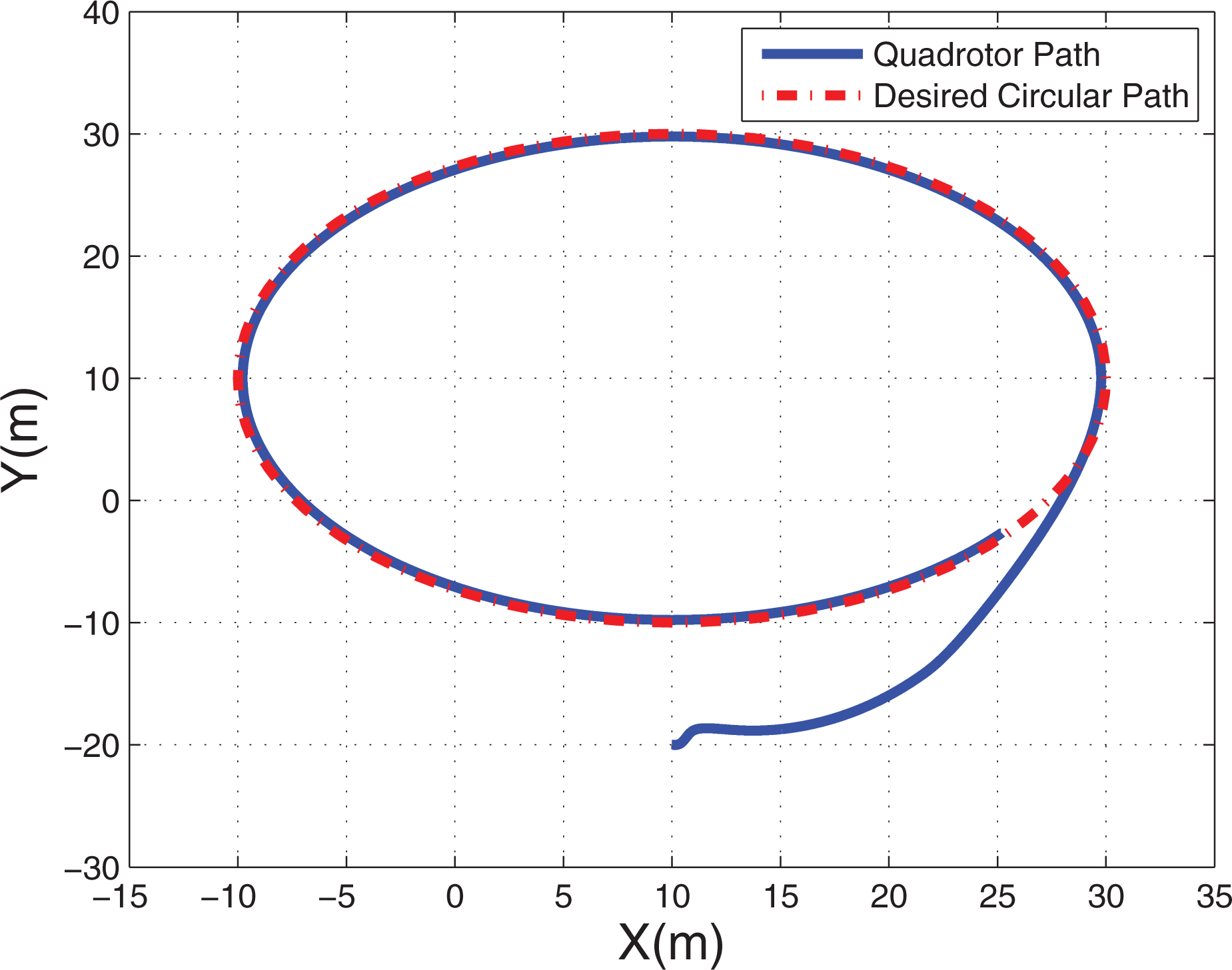
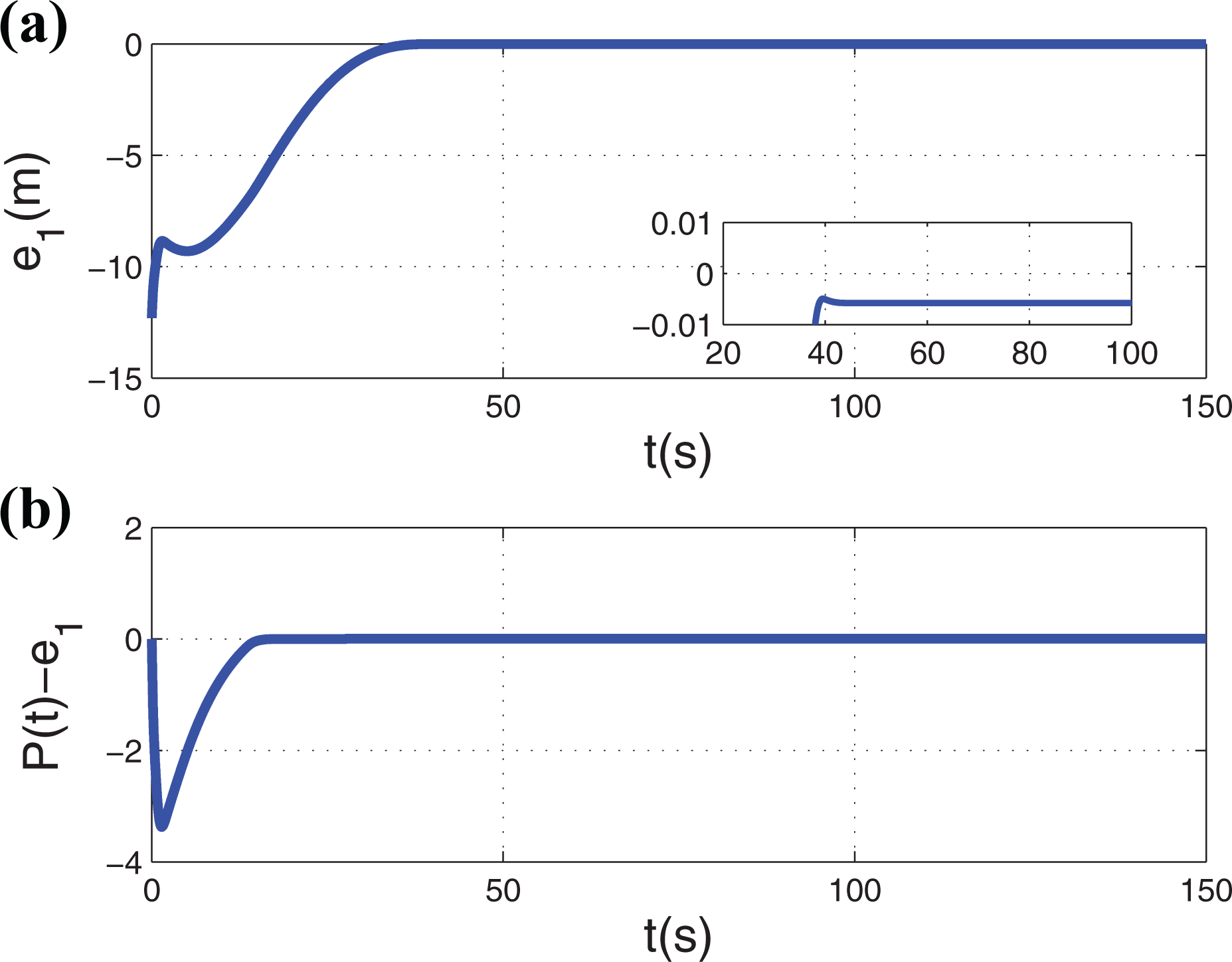
Case C: The design parameters of PTGL in this article are selected as the same as that in Case B. The prescribed time T is set as 40 s in this case.
Figure 24 shows that quadrotor takes longer time to settle on the desired path compared with Figure 22 in Case B. Figure 25 demonstrates that t 2 is 39.42 s, which is approximately equal to prescribed time T. Cross-track error e 1 is still equal to −0.0055 m. It can be summarized that PTGL not only can achieve convergence at prescribed time but also can retain the higher precision of HPGL, compared with conventional NLGL method. Although the tracking accuracies in numerical simulation are high enough, it should be noted that it is impossible to achieve such high precision in practice due to the influences of sensor errors and wind variations.

Result of circular path following using PTGL. PTGL: prescribed-time guidance law.

(a and b) Cross-track error of circular path following using PTGL. PTGL: prescribed-time guidance law.
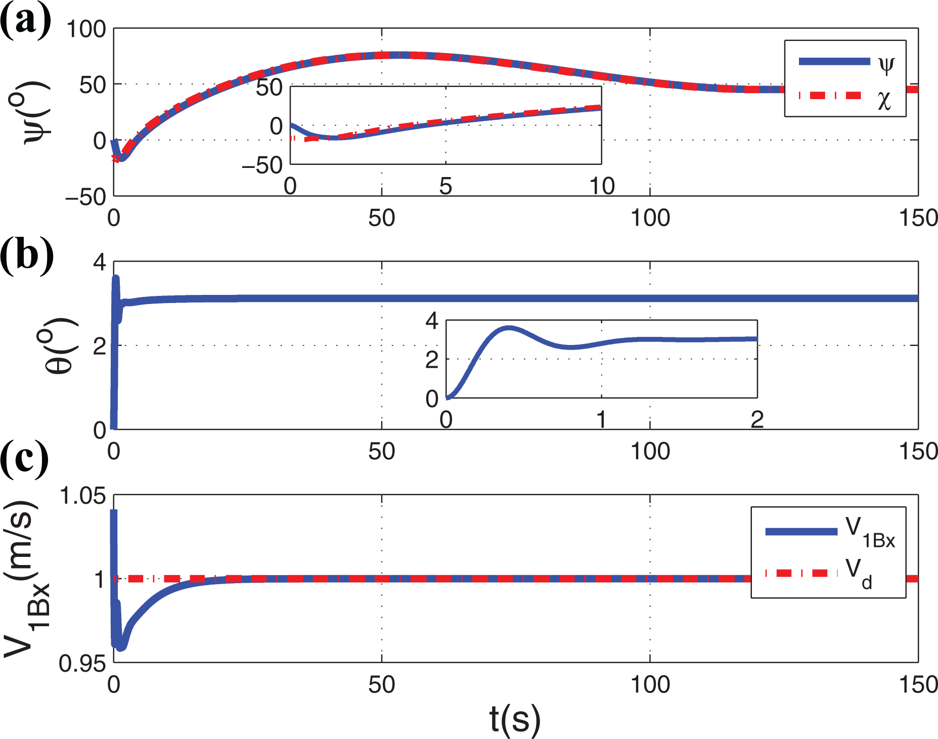
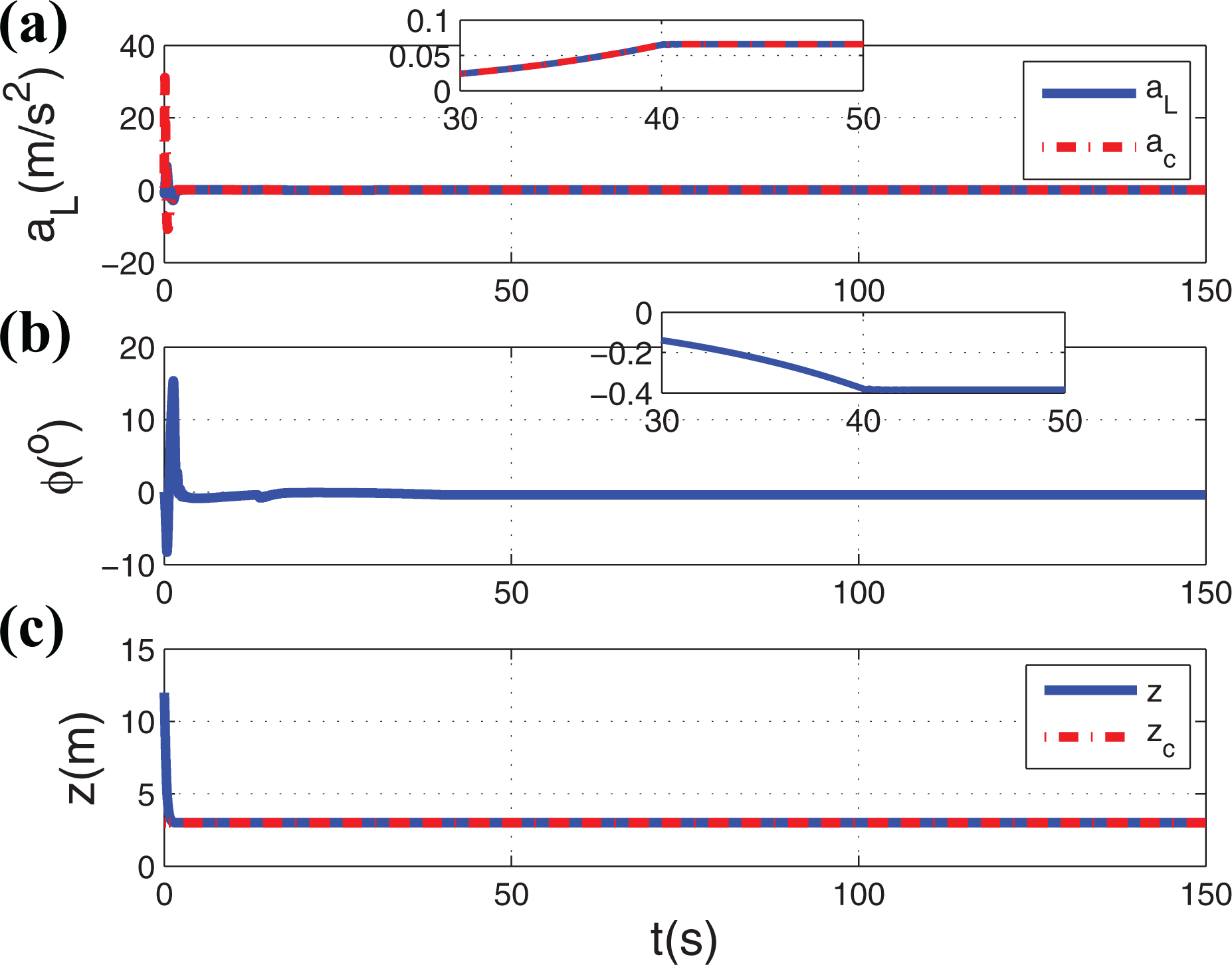
Similarly to Case B in “Straight line following” section, tracking performance of course hold controller and longitudinal controller are displayed in Figure 26. Course hold controller drives yaw angle ψ to track the course angle χ accurately to realize no-sideslip flight, while longitudinal controller makes quadrotor achieve the desired velocity Vd by pitching to desired pitch angle. In Figure 27, lateral controller generates roll angle ϕ, to follow the lateral command acceleration ac . It can be seen that roll angle ϕ and lateral acceleration converge to stable values after prescribed time, because cross-track error e 1 achieves convergence exactly at prescribed time. However, different from Case B in “Straight line following” section, it should be noted that stable values of ϕ and lateral acceleration are not equal to zero, which is used to achieve exact circular path following. In addition, tracking performance of height value can also be guaranteed similarly to Case B in “Straight line following” section.

(a to c) Tracking performance of course hold controller and longitudinal controller.

(a to c) Tracking performance of lateral controller and height controller.
Case D: In this case, PTGL is applied in different initial conditions and disturbance, to demonstrate that effect of PTGL will almost be unaffected by drastic changes in height and velocity. The simulation conditions are listed in Table 2.
Simulation conditions of Case D.

Compared with Case C, Case D.1 changes the initial height of quadrotor and Case D.2 changes the initial velocity of quadrotor. Case D.3 adds disturbance
Result of circular path following using PTGL in Case D.1. PTGL: prescribed-time guidance law.
(a and b) Cross-track error of circular path following using PTGL in Case D.1. PTGL: prescribed-time guidance law.

(a to c) Tracking performance of course hold controller and longitudinal controller in Case D.1.
(a to c) Tracking performance of lateral controller and height controller in Case D.1.

Result of circular path following using PTGL in Case D.2. PTGL: prescribed-time guidance law.

(a and b) Cross-track error of circular path following using PTGL in Case D.2. PTGL: prescribed-time guidance law.

(a to c) Tracking performance of course hold controller and longitudinal controller in Case D.2.

(a to c) Tracking performance of lateral controller and height controller in Case D.2.

Result of circular path following using PTGL in Case D.3. PTGL: prescribed-time guidance law.

(a and b) Cross-track error of circular path following using PTGL in Case D.3. PTGL: prescribed-time guidance law.

(a to c) Tracking performance of course hold controller and longitudinal controller in Case D.3.

(a to c) Tracking performance of lateral controller and height controller in Case D.3.
In summary, the change in height does not have any influence on the effectiveness of PTGL whether in theory or in practice. The change in velocity will influence the convergence precision of e 1 slightly in theory, according to the analysis in proof of Theorem 1. However, this influence can be negligible in actual use.
Remark 6
Although the PTGL proposed could accomplish precise path following at predesigned time T, the prescribed-time convergence is realized via changing its flight path, instead of flying directly to the desired path. It should be noted that PTGL will cost more spaces compared with conventional path following methods. Therefore, PTGL is suitable for path following tasks in more open areas. If the surrounding environment is relatively narrow, such as a narrow tunnel, it is not recommended to use PTGL, to ensure the safety of quadrotor.
Complex path following
In this subsection, quadrotor is driven to follow a complex path, which is a combination of straight and circular path, just like a track. The positions of four waypoints of the complex path are set as

while the radius of the arcs is equal to 20 m. The initial position and velocity of quadrotor are
To increase the persuasiveness of PTGL, two cases of simulation are performed. Case A.1 sets prescribed time T as 25 S, while Case A.2 sets T as 90 S.
Figures 40 and 41 show that PTGL is able to make quadrotor follow the desired complex path effectively with high tracking precision. The convergence time t 3 of Case A.1 is 25.12 s, which is approximately equal to prescribed time T. The tracking errors of straight line and circular path are the same as the results in previous two subsections.

Result of complex path following using PTGL in Case A.1. PTGL: prescribed-time guidance law.

(a and b) Cross-track error of complex path following using PTGL in Case A.1. PTGL: prescribed-time guidance law.
Tracking performance of course hold controller and longitudinal controller are displayed in Figure 42. In Figure 43, it can be seen that roll angle ϕ and lateral acceleration converge to zero at prescribed time, so that e
1 achieves convergence exactly at prescribed time. When flight path switches between straight line and arc, the lateral acceleration command will generate a step. The reason for this phenomenon is that the

(a to c) Tracking performance of course hold controller and longitudinal controller in Case A.1.

(a to c) Tracking performance of lateral controller and height controller in Case A.1.
Similarly, Figures 44 and 45 display the results of Case A.2. The convergence time of Case A.2 is 90.26 s, which is approximately equal to prescribed time T. Tracking performance of course hold controller, longitudinal controller, lateral controller, and height controller are shown in Figures 46 and 47, respectively, which are similar to Figures 42 and 43. It should be noted that due to the longer prescribed time set in Case A.2, quadrotor achieves prescribed-time convergence on circular path instead of on straight line path as in Case A.1. According to the results in Case A.1 and Case A.2, it can be concluded that PTGL can also adjust the convergence time freely to achieve accurate path following even if the path is complex.

Result of complex path following using PTGL in Case A.2. PTGL: prescribed-time guidance law.

(a and b) Cross-track error of complex path following using PTGL in Case A.2. PTGL: prescribed-time guidance law.

(a to c) Tracking performance of course hold controller and longitudinal controller in Case A.2.

(a to c) Tracking performance of lateral controller and height controller in Case A.2.
Conclusion
In this article, a new control structure is proposed for quadrotor, which can perform a non-sideslip and bank-to-turn flight scheme just like a fixed-wing UAV. Based on it, a PTGL is presented to realize path following at pre-designed time by means of combining sliding mode control and a compensation function p(t). Simulations demonstrate that the PTGL could make quadrotor converge to desired path at prescribed time precisely whether in linear or circular path following. Meanwhile, high-precision tracking of PTGL is verified by comparison with traditional guidance law. In the future research, the robustness of the method to wind disturbances will be verified and the implementation on an experimental testbed will be performed.
Footnotes
Declaration of conflicting interests
The author(s) declared no potential conflicts of interest with respect to the research, authorship, and/or publication of this article.
Funding
The author(s) disclosed receipt of the following financial support for the research, authorship, and/or publication of this article: This work was supported by the National Nature Science Fund of China [No. 61703125].