
Abstract
In view of the difficulties in the attitude determination of wrecked submarine and the automatic attitude matching of deep submergence rescue vehicles during the docking and guidance of a submarine rescue vehicle, this study proposes a docking method based on parameter adaptive control with acoustic and visual guidance. This study omits the process of obtaining the information of the wrecked submarine in advance, thus saving considerable detection time and improving rescue efficiency. A parameter adaptive controller based on reinforcement learning is designed. The S-plane and proportional integral derivative controllers are trained through reinforcement learning to obtain the control parameters in the improvement of the environmental adaptability and anti-current ability of deep submarine rescue vehicles. The effectiveness of the proposed method is proved by simulation and pool tests. The comparison experiment shows that the parameter adaptive controller based on reinforcement learning has better control effect, accuracy, and stability than the untrained control method.
Keywords
Introduction
Submarines are characterized by good concealment, long range, and strong penetration, these characteristics contribute to making it widely used. However, the crew avoiding danger remains to be a difficult problem because of the particularity of the working environment. 1 –5 Incomplete statistics reveals that more than 400 accidents involving submarines in peaceful environments worldwide have been reported since 1900, resulting in the sinking of more than 180 submarines and the death of more than 3000 sailors. 6,7 The accident of the Russian navy’s “KURSK” nuclear submarine in August 2000 shocked the world and gained people’s attention for research on submarine rescue technology. 8
After the submarine accident, the crew could escape in many ways. Waiting for a deep submergence rescue vehicle (DSRV) is the most reliable and effective among many methods worldwide. 9 –12
On April 10, 1963, the US navy’s nuclear submarine “Thresher” had an accident during a deep diving test in the Atlantic Ocean, resulting in the death of 129 people. 13 This event prompted the US navy to propose a deep submersible rescue plan in May 1964. Lockheed Missiles teamed up with the Space Company to build the US DSRV-1 Mystic, the world’s first DSRV, which was launched in 1970. The Avalon was built in 1971, which was roughly the same size and had similar functions as the Mystic. Both vehicles entered service in 1977 and retired in 2000. Russia has two series of DSRVs, namely, Bester and Priz. The Priz series consists of four DSRVs, namely AS-26 (1986), AS-28 (1989), AS-30 (1989), and AS-34 (1991). 14 The LR series were produced by Perry Slingsby systems in British. The LR5 is used by the North Atlantic Treaty Organization for submarine rescue; it has participated in the rescue activities of the Russian “KURSK” nuclear submarine. 15,16
China began its technical research on DSRVs in the 1970s and placed its self-developed DSRV into service in 1987. The DSRV has a maximum dive of 600 m and a maximum speed of 4 knots. It can be used for docking and rescue when the current is less than 1.5 knots, the water visibility is more than 0.5 m, and the submarine is not inclined too much. In 2008, China purchased DSRV LR7 from Britain.
The docking process 17 of DSRVs and wreck submarines is important in deep-dive rescue. The following control method 18 is related to the success of docking. Xia et al. 19 designed an adaptive fuzzy control law using command filtered backstepping method considering the system uncertainties and unknown disturbances of a DSRV. A second-order filter in the design of the controller was introduced to approximate the virtual control signal and its derivative. However, only a simulation test was conducted for verification. Control accuracy and other problems may appear in an actual test. Park et al. 20 introduced a docking process for a testbed autonomous underwater vehicle (AUV) using a charge-coupled device camera. A two-stage final approach for stable docking at the terminal was suggested. A vision guidance controller was designed with proportional integral derivative controllers for the vertical and horizontal planes. However, this visual guidance docking process hardly obtains the attitude of the docking device, which is only applicable to the case of small deviation angle of the docking device. Teo et al. 21 presented an AUV docking method that resists unknown water currents. The approach incorporated a Tagaki Sugeno Kang fuzzy inference system. A current compensator was designed and applied to fuzzy docking guidance so that the vehicle can maintain course under the disturbance of water flow. However, the method fixed the direction of the docking device and was not universally applicable. Li et al. 22 designed a docking control algorithm for AUVs. A control scheme of a three-layer control loop structure was proposed and embedded with an online current compensator and effective control parameter setting. The validity of the method was verified through experiments. However, this method had a weak anti-interference ability. When the flow velocity is large, the cross-track error increases, resulting in docking failure.
Therefore, the underwater rescue docking process faced the following problems:
Target identification and positioning efficiency: In the process of guidance, an AUV is often used to determine the position and attitude of the wrecked submarine before rescue and thus time consuming.
Adaptive controller: The position of the submarine wreck, which requires the controller to have strong anti-interference ability and self-adaptability is often accompanied by severe sea conditions.
Control accuracy: High control accuracy is needed to improve the success rate of docking between DSRV and submarine.
A new docking guidance method based on visually assisted underwater acoustics is proposed to address problems in underwater rescue docking process. This method measures the attitude of a submarine combined with the visual and acoustic to adjust the DSRV. Moreover, it omits the process of obtaining the information of the wrecked submarine in advance, thus saving considerable detection time and improving rescue efficiency. The automatic matching problem of submarines with large inclination under unfavorable sea conditions is solved. A parametric adaptive controller based on reinforcement learning is designed in this study. The parameters of the controller are trained through reinforcement learning, which makes the controller adaptive to the parameters; thus, the control effect of the DSRV in the complicated underwater environment and the accuracy and stability of the docking process are improved. In addition, achieving the required angle and accuracy of docking and increasing the complexity of thrust distribution and energy consumption are difficult if the large inclination positioning of a DSRV is achieved through propellers only. A ballast tank combined with a pump valve (solenoid valve) system was used to achieve the vertical and horizontal tilt control of a test DSRV.
The rest of this article is organized as follows: The second section proposes the underwater docking guidance method combining vision and acoustics. The third section designs a parametric adaptive controller based on reinforcement learning, including the DSRV motion control and water tank regulation control algorithms. The fourth section presents the simulation experiment of the docking process. The fifth section discusses the experiment on DSRV docking and compares the results with that of the conventional control algorithm, thereby proving the advantages and effectiveness of the proposed method.
Acoustic and visual guidance during docking
The attitude of the submarine cannot be acquired due to planar imaging if visual guidance is the only method used during docking. Determining the center position of the target due to the uncertain attitude of the target is difficult if the acoustic guidance method is adopted. Visual and acoustic methods are combined to identify and locate objects. First, the position of the docking device is determined by the ultrashort baseline (USBL) positioning system. The target is identified and positioned on the basis of the single shot multibox detector (SSD) algorithm using the camera mounted on the DSRV after the DSRV arrives near the docking device. The target is positioned at the center of the image by adjusting the position of the DSRV. The attitude of the DSRV is adjusted using a water tank so that the slant distance measured by the four USBLs is approximately equal. Second, the position of the DSRV is fine-tuned, placing the target at the center of the image again. Lastly, the DSRV dives, and the position and attitude of the DSRV are adjusted to complete the docking.
Visual guidance
The SSD algorithm 23 is used to identify and locate the docking device. The DSRV is equipped with an underwater searchlight, and a reflector is installed on the docking device to reflect the light, which is identified by the camera.
Deep learning is used to study the real-time detection and positioning of relative moving target points. The SSD method is adopted to extract the convolution features of multiple scales with VGG16 as the network model under the TensorFlow framework.
The image physical coordinates of the target’s center point and four corners are obtained and then converted into the camera coordinate system. The position of the target in the geodetic coordinate system is obtained in accordance with the transformation relation between the camera and geodetic coordinate systems. This target position is the target point of DSRV.
The pinhole model is taken as the imaging model of the camera, as shown in Figure 1, which represents three different coordinate systems; (XW , YW , ZW ) is the world coordinate system, also known as global coordinates; (xoy) is the camera coordinate system, which takes the focal point of the camera model as the origin, the direction of the captain as the x-axis, direction of the boat width as the y-axis, and the optical axis of the camera as the z-axis. The image coordinate system is divided into image pixel (XOY) and image physical coordinate systems (XfOfYf ). The origin of the image physical coordinate system is the intersection of the optical axis of the lens and the imaging plane. The X- and Y-axes are parallel to the x- and y-axes of the camera coordinate system, respectively. The image pixel coordinate system, also known as computer image coordinate system, is a planar rectangular coordinate system fixed on the image with the unit of pixels and is located in the upper left corner of the image. The Xf - and Yf -axes are parallel to the X- and Y-axes of the physical coordinate system of the image.

Schematic representation of camera coordinate system transformation.
The transformation relationships among the coordinate systems are as follows:
The transformation relationship between the world and camera coordinate systems is as follows

where T is the coordinates of the origin of the world coordinate system in the camera coordinate system and the matrix R is the orthogonal rotation matrix. R meets the following constraints

The transformation relationship between the image and camera coordinate systems is as follows:
The point p in the camera coordinate system is converted to the point P in the image physical coordinate system according to the following transformation relationship

where f is the camera parameters. The above equation is expressed by homogeneous coordinates as follows
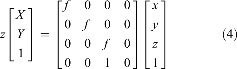
The above formula is converted into the image coordinate system

where u and v are the image coordinates, u
0 and v
0 are the image center coordinates.
The transformation relationship between the world and image coordinate systems is as follows

The above equation is converted into homogeneous coordinates.
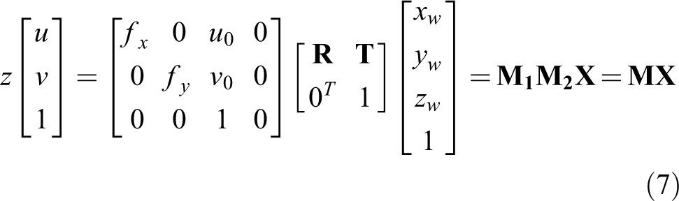
This equation is the mathematical expression of the pinhole model. Figure 2 shows that the internal and external parameters of the camera can be solved using several known object points, and the coordinates of the corresponding image points under the condition that the internal parameters of the camera are determined.
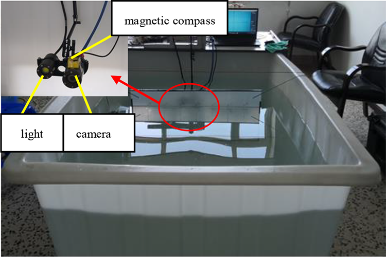
Underwater camera calibration test.
Table 1 lists the camera parameters obtained through the experiment.
Camera parameters.

The position of the target relative to the DSRV in the world coordinate system can be solved in real time according to the distance between the target point and the image center in the imaging position of the camera after obtaining the camera parameters. The movement of the DSRV is controlled until the target is in the imaging center, so that the DSRV and the rescued submarine are aligned in the vertical direction. When the target appears in the imaging center, the distance from the DSRV to the target can be obtained in accordance with the actual size of the target and the imaging size.
Acoustic guidance
After the DSRV and the submarine are aligned in the vertical direction with the visual guidance, the DSRV is guided to the submarine’s attitude with acoustic guidance. Figure 3 shows the installation of four underwater acoustic transponders on the docking device and the installation of the positioning base station on the docking guidance system of the DSRV.

Installation position of the four transponders on the docking platform: (a) main view and (b) top view.
The target attitude of DSRV, heading angle ψ, trim angle θ, and heeling angle ϕ, are calculated using formula in accordance with the distance of the underwater acoustic transponders and DSRV. Figure 4 shows that point O is the position of the DSRV; (xw 1, yw 1), (xw 2, yw 2), (xw 3, yw 3), and (xw 4, yw 4) are the positions of the four underwater acoustic transponders

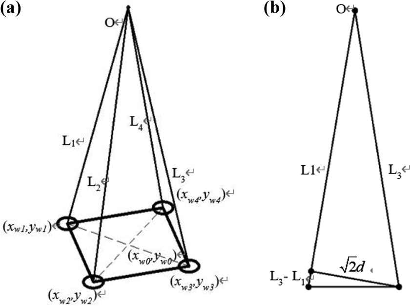
Attitude calculation diagram: (a) main view and (b) side view.
where


L 1, L 2, L 3, and L 4 are the distances measured by four underwater acoustic transponders. d is the mounting distance of two adjacent underwater acoustic transponders. The underwater acoustic transponder with the minimum distance measured as no. 1 was set clockwise, and nos. 2, 3, and 4 were set counterclockwise.
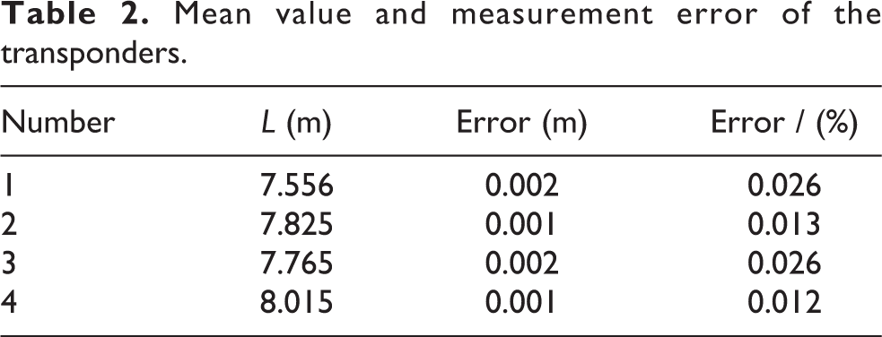
The attitude of a lifeboat is highly required during docking. Therefore, testing the positioning accuracy of the USBL is necessary. The docking platform is placed underwater, and the base station of the docking guidance system is suspended at a certain depth in the water for static test. The sound velocity profiler is used to collect the sound velocity information of the tank, and the sound velocity is modified before the test. Table 2 presents the measured standard deviation of the four transponders at 7.825, 7.556, 7.765, and 8.015 m, with a maximum value of 0.002 m. The positioning system keeps the measured values of the four transponders’ oblique distance unchanged, and the error is less than 1 cm, meeting the requirements of docking.
Mean value and measurement error of the transponders.
Parameter adaptive controller based on online learning
The development of science and technology has led to an increasing number of control methods being applied in the AUV field. 24 The S-plane control method 25 is adopted to identify the propeller control of DSRV, and the integral separation proportional–integral–derivative (PID) control method 26 is adopted to achieve the water tank adjustment of DSRV. The deep deterministic policy gradient (DDPG) method 27 is used to train the control parameters for obtaining the online learning ability of the controller and improve the adaptability of the parameters.
Hydrodynamic modeling
The CHUAN SUO (CS) deep submergence vehicle was taken as the experiment platform (Figure 5).

CHUAN SUO deep submergence rescue vehicle.
A dynamic model of the DSRV is established 28,29

where M is the inertia coefficient matrix of the system that can satisfy
The parameters of each matrix are expressed as follows 30


where

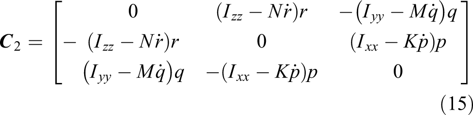


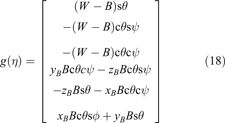

where W and B are the gravity and buoyancy of the AUV.
Accurate hydrodynamic coefficients are needed in the simulation training of controller parameter adjustment through deep reinforcement learning. Table 3 presents that the hydrodynamic coefficient of the DSRV is obtained through calculation and a model test.
Hydrodynamic coefficients of the DSRV.

DSRV: deep submergence rescue vehicle.
Design of controller
The DSRV has two control objects: propeller and regulating tank. The speed, position, heading, and depth of the DSRV can be controlled by controlling the output force of the propeller. The roll and trim of the DSRV can be controlled by adjusting the water tank. The S-plane control algorithm is adopted for propeller control, and the integral separation PID control algorithm is adopted for water tank adjustment. At the same time, the DDPG method is used to train the parameters of the controller, and the variable parameter adaptive control of the controller is identified.
Basic control algorithm
S-plane controller
S-plane control learns from the PID method based on fuzzy control. 31 Figure 6 is the control surface of the S-plane method which expresses the relationship between deviation, deviation rate and control force. The algorithm is expressed as follows


Control surface of the S-plane.
where i is the ith degree of freedom . ei
and
Integral separation PID controller
The CS uses the water tanks and an electromagnetic valve to control the trim and heel.
Figure 7 shows that the ballast tanks are arranged. There are four tanks arranged on both sides of the compressive cabin to adjust heel. There are two tanks arranged on both ends of the compressive cabin to adjust trim. The pump and valve system is installed in the compressive cabin. The solenoid valve is controlled for ballast water regulation.

The tank arrangement for CS. CS: CHUAN SUO.
By manually controlling the solenoid valve to adjust the vertical and horizontal inclination tests, it is found that the changes of CS inclination angle are basically linear with time. In this study, integral separation control algorithm based on PID is used to calculate the opening and closing time of solenoid valve, so as to realize the automatic control of trim and heel

where k is the serial number of the current order. t is the opening or closing time.
Variable parameter controller based on reinforcement learning
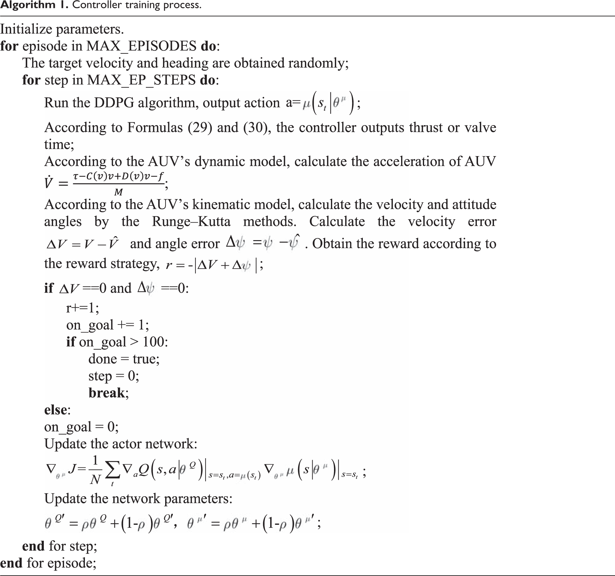
The DDPG algorithm is adopted to train the parameters of the controller, and the real-time adaptive adjustment of parameters is identified.
DDPG is a deep reinforcement learning algorithm that combines Actor Critic and deep q network (DQN). The concept is to apply the memory banks in the DQN structure and the idea of two neural networks with the same structure but different frequencies of parameter update on Actor Critic. The DDPG algorithm is divided into two parts: Main Net and Target Net, as shown in Figure 8. Each part includes an ActorNet and a CriticNet. The ActorNet outputs control system parameters, and the CriticNet evaluates each action. In consideration of a standard RL problem, a finite Markov decision process, which comprises a current state st , an action space at , a reward function r, and the next state st +1, is established. During the learning process, the reward value is adjusted constantly, and it can be found that the absolute value of the difference between the actual motion state of the DSRV and the target state as the system reward is the best. Hence


Deep deterministic policy gradient.
where
Experience is gained from the experience pool for learning. The 6-DOF action at
form

If the target policy is deterministic, then a function

where λ is the learning rate. According to Q-learning
32
and considering the function approximators parameterized by

The neural network is trained to minimize the loss function so that the actual Q value tends to the target Q value.
A parameterized actor function

where N is the number of learning. The idea of using DDPG to train the controller parameters is to input the speed and attitude errors of the DSRV into the algorithm as the state, and the algorithm outputs the controller parameters. The neural network can be trained to obtain the optimal parameters, so that the motion state of the DSRV can stabilize toward the target state.
The application of DDPG in DSRV control requires the establishment of a critic


Formulas and are used for training in two reinforcement learning systems. ak and aK represent the action output of the two systems, respectively. Thus, the controller can be expressed as


The learning-and-training process of the controller is shown in Algorithm 1.
Controller training process.

Python is used to build the training environment, and the training results are as follows:
In Figure 9, the abscissa represents the episodes of training, and the ordinate represents the total reward of each episode. A total of 10,000 episodes are created during simulation training. Each training episode is updated with 500 steps. The control range of velocity (0–3 m/s), the control range of heading angle (−180° to 180°), and the control range of pitch angle (−45° to 45°) can be obtained through training. Figure 9 shows that when the reward value basically converges to 50, the training is successful. The parameters obtained from the training are applied to the DSRV after training in the Python simulation environment. The self-learning ability of the controller parameters is maintained. Real-time online learning is conducted to optimize the parameters of the controller continuously and adapt to different and complex real environments during an actual operation.

Training results of control parameters based on DDPG. DDPG: deep deterministic policy gradient.
Thrust allocation
The CS is equipped with six thrusters, including two main propellers, two side propellers, and two vertical propellers. The placement of the thrusters on the CS is shown in Figure 10. l 1, l 2, l 3, l 4, l 5, and l 6 are the moment arms for each propeller to the center of the CS. Thus, the relationship between the force required at the 4-DOF of CS can be obtained as follows


Thruster plan of the CS underwater vehicle. CS: CHUAN SUO.
where X, Y, and Z correspond to the forces on 3-DOF; N is the torque; and T 1 and T 2 are the thrusts of main propellers, T 3 and T 4 are the thrusts of side propellers, T 5 and T 6 are the thrusts of vertical propellers.
The formula (31) shows a redundant propulsion system. Consider the two constraints: the main propellers only adjust the longitudinal velocity and the vertical propellers only adjust the vertical velocity. Thus
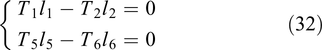
where
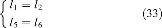
Combining formulas and

When T
1, T
2, T
3, and T
4 are greater than

Two situations exist for T
3 and T
4. Firstly, when they are greater than

Secondly, one of them is greater than T max, assuming T 3 > T max > T 4. T 3 and T 4 both adjust the lateral and heading motions of CS. The principle of “heading priority” is adopted for the thrust allocation, that is, the torque of turning bow is first satisfied

If
Simulation experiment
Deep-dive rescue is divided into four stages. The first stage is the approach stage. The DSRV is usually hoisted and lowered vertically on the mother ship and then dives after entry on this stage. The DSRV sails at a fixed depth, heading, and velocity to within 10 m of the wrecked submarine. The second stage is the dynamic positioning stage of the 4-DOF control. In this stage, the 4-DOF control of the heading and the longitudinal, transverse, and vertical positions are identified and named 4-DOF dynamic positioning. The DSRV eventually hovers at an altitude above the wrecked submarine. In the third stage, the attitude is adjusted on the basis of the 4-DOF dynamic positioning so that the DSRV could hover on the wrecked submarine with the target trim angle and the heeling angle. Finally, the 6-DOF dynamic positioning is identified. The fourth stage is the approach and lifesaving stage. After approaching a certain height, the DSRV attitude is kept, and the translation of three positions is controlled so that the docking structure of the DSRV and the rescue platform of the wreck submarine can be connected. Misalignment or skew may occur during this process, and adjusting the position or attitude so that the DSRV can be socketed with the rescue platform of the wreck submarine is necessary. Finally, the people on the wrecked submarine can safely enter the DSRV to complete the lifesaving stage through water light to identify the atmospheric pressure of the lifeboat passage.
The simulation test environment is built to simulate the docking process between the DSRV and the submarine, as shown in Figure 11. Figure 11(a) shows the DSRV sailing toward the target wrecked submarine. Figure 11(b) shows the DSRV entering the communication range of USBL. Figure 11(c) shows the positioning of the DSRV guided by visual and acoustic sense and the docking completed by the controller.

Simulation of the deep submergence rescue: (a) the first stage, (b) the second stage, and (c) the third and fourth stages.
In the simulation, the DSRV adjusts the heading and sails to the wrecked submarine at a fixed depth and speed. Figure 12(a) and (b) shows the control results. The transverse, longitudinal, and vertical positions and the heading stability of the DSRV are controlled at the target value to achieve the dynamic positioning of 4-DOF control and finally hovers on the wrecked submarine when approaching the range of approximately 10 m of the wrecked submarine. The attitude of the DSRV is adjusted to make it hover on the wrecked submarine with the target trim angle and heeling angle based on the 4-DOF dynamic positioning. Finally, the 6-DOF dynamic positioning is achieved. Figure 12(d) shows the attitude control results. Figure 12(c) shows that the three positions shift under the condition of three attitude control after approaching the height of the platform, so that the skirt body of the lifeboat is connected with the rescue platform of the wreck boat. Finally, the three positions are shifted under the premise of maintaining the attitude after approaching a certain height of the submarine. This action is performed so that the skirt of the DSRV connects with the rescue platform of the wrecked submarine.

Simulation results: (a) speed control result, (b) heading control result, (c) position control result, and (d) attitude control results.
According to the simulation results, the DSRV can successfully reach the target position to complete the docking rescue task using the proposed control method. The control effect is stable, and the convergence speed is fast. Therefore, the adaptive control method proposed in this study is effective and feasible.
Tank experiment
A tank experiment, as shown in Figure 13, was performed. The docking device adopts an articulated skirt structure located in the middle of the DSRV (red circle range), and the scale ratio of the carrier is 1:2. The experiment is conducted in the deep pool laboratory. The pool is 50 m long, 30 m wide, and 10 m deep.

Tank experiment: (a) the articulated skirt and (b) installation of the articulated skirt.
The DSRV reaches the target position by controlling the propeller and stabilizes at the target position in the test. The DSRV dives to the target depth and adjusts its bow, trim, and rake to the target value.
Figure 14(a) and (b) shows the horizontal and longitudinal position control curves, respectively. The horizontal coordinate represents the running time of the system, the vertical coordinate represents the transverse and longitudinal positions of the DSRV in the geodetic coordinate system, and the center of the geodetic coordinate system is selected in the center of the tank. Results show that the proposed DDPG-based variable parameter control method can control the DSRV positioning at the target position well. In addition, it can control the DSRV to reach the target position faster and more steadily than the traditional control method. Figure 14(c) shows the depth control curve of the lifeboat. The DSRV dives down to a depth of 6 m after reaching the target position. The controller can stabilize the DSRV at the target depth well. Figure 14(d) to (f) shows the heading, trim, and heeling control curves of the DSRV, respectively. The trim and heeling control of DSRV are identified through water tank adjustment. The control curve of the proposed control method is stable. In conclusion, compared with the ordinary fixed parameter control method, the DDPG-based variable parameter control method has certain anti-flow ability and adaptability and can control DSRV navigation and docking more quickly and steadily.

Control results of the tank experiment: (a) horizontal position control results, (b) longitudinal position control results, (c) depth control results, (d) heading control results, (e) trim control results, (f) heeling control results.
Figure 15 shows that the docking is completed with acoustic and visual guidance after the adjustment of the position and attitude of the DSRV.

Screenshots of the docking process: (a) towards the target and (b) completing docking.
According to the test results, the method of combining visual and acoustic sense can successfully guide the DSRV to complete the docking task under the condition of unknown wrecked submarine posture. Compared with the ordinary control method, the DDPG-based parameter adjustment control method has stronger adaptability to the environment, has a certain anti-flowability, and can control the DSRV to complete the docking task more quickly and steadily.
Conclusions
This study proposes a guidance method based on the combination of vision and acoustics, considering the difficulties in determining the attitude of the wrecked submarine and controlling the instability in submarine rescue. A variable parameter controller based on reinforcement learning is designed. The effectiveness of the proposed guidance method is proven by simulation and tank tests. The attitude of the submarine can be measured during docking to adjust the attitude of the DSRV in real time while combining vision and acoustics. The process of obtaining the wreck submarine information in advance is omitted; hence, considerable detection time is saved, and rescue efficiency is improved. The automatic matching problem of a submarine with large inclination under unfavorable sea conditions is solved. The controller with the DDPG-trained parameters and the controller without training are compared through a tank experiment; results show that the variable parameter controller based on reinforcement learning has better control effect. Moreover, the proposed controller is more suitable for complex and changeable underwater environment and improves the accuracy and stability of the docking process.
Footnotes
Declaration of conflicting interests
The author(s) declared no potential conflicts of interest with respect to the research, authorship, and/or publication of this article.
Funding
The author(s) disclosed receipt of the following financial support for the research, authorship, and/or publication of this article: The work was supported in part by the Equipment Pre-research Project (Project Number 41412030201), and the China National Natural Science Foundation (Project Numbers 51779057 and 51709061).