
Abstract
Flexible bearing is an important component of harmonic reducer which is widely used in automation equipment, especially in industrial robots. Studying its mechanical characteristics has great significance. In this article, the theoretical model of contact force between rolling elements and outer ring is established based on three bending moment equations, and the characteristics of CSF-40-80 flexible bearing are also studied by finite element method analysis. Analysis of equivalent stress at static state has shown that it already has large equivalent stress before load and that external load has a great influence on it. The dynamic and contact characteristics of it after actual assembly are also presented in this article. The displacements and velocities at different locations at different times of the movement are found to be different, which can provide a reference for the manufacture of flexible bearing.
Introduction
The harmonic reducer was proposed by Musser 1 based on the thin-shell elastic deformation theory in 1953. Harmonic drive system offers significant advantages over conventional systems, including high positioning accuracy with zero backlashes, reduced size, reduced weight, and increased reduction ratios. Therefore, it is widely used in military, industrial, agricultural, and other fields, especially industrial robots. 2,3 Recently, the development and study of robots has been a very hot topic. Xiong 4 did the simulation of the steering movement of the soccer robot. The steering movement of the wheeled soccer robot is controlled by artificial intelligence control algorithm. Jaber and Bicker 5 built a condition monitoring system of industrial robots based on signal processing. Vibration signals are used to study the failure analysis and fault detection of industrial robots. Chao et al. 6 proposed a deep learning-based object-detection method for a five-fingered industrial robot hand model to improve the accuracy of the robotic grasp. Harmonic reducer is indispensable to these mobile robots. Harmonic reducer consists of three components which are a wave generator, a nonrigid flexspline, and a rigid circular spline, and flexible bearing is the core component of wave generator, which is a compact component with precise structure and small size. 7 When the arm of industrial robot works, the main load at the joint will be transferred to the reducer at the joint. The flexspline at the joint bears load from itself and external load. Deformation and velocity increase of flexspline resulted from the contact between the outer ring of flexible bearing of wave generator and the inner wall of flexspline. Flexible bearing makes the harmonic reducer to reach high performance through its elastic deformation, while it is easy to fail because of the large cyclic load. The life of flexible bearing determines the service life of the whole harmonic reducer even in the industrial robots; therefore, the design and manufacture of flexible bearing are highly demanded. It is difficult to install sensors and other devices for dynamic measurement. Therefore, simulation turned out to be important in the study of flexible bearing.
Ostapski and Mukha 8 proposed a method for calculating the deformation of thin-walled shell structure model. They analyzed the stress and strain of flexible bearing using finite element method (FEM) analysis. Zou et al. 9 treated wave generator (including flexible bearing) as a rigid body and studied the stress and deformation of flexspline under no-load and load conditions. But they did not analyze the mechanical properties. Huang et al. 10 established the calculation model of friction torque and heat capacity for flexible bearings and obtained the temperature distribution of the inner and outer ring and the rolling elements. Ueura and Kiyosawa 11 made a comprehensive study on the failure mode and failure mechanism between the outer ring of flexible bearing and the inner wall of flexspline. They established a mixed lubrication model with asperity contact model. The flow field and pressure distribution between the inner wall of flexspline and outer ring in different environments are analyzed. Zheng and Yang 12 regarded flexspline as a whole and studied its failure mechanism. It reports that the main reason for the failure of the flexspline was that the working surface of the gear has local microcracks, which results in abnormal contact and local rupture during the working process. Liu et al. 13 designed a new machine to test fatigue life of flexible bearing. However, the testing machine can only simulate the condition when flexspline is the active part but cannot simulate the actual working state when wave generator is the active part.
Unfortunately, current research about harmonic transmission is more about regarding flexspline or wave generator as a whole and the study of the dynamics performance caused by flexible bearing is rarely mentioned. Therefore, this article studies the static and dynamic mechanical properties of flexible bearing and analyzes the dynamic performance under actual assembly, which provides theoretical support for the optimization of harmonic reducers and the manufacture of high-performance harmonic drive systems.
Theoretical model of external load
Analysis of outer ring
In harmonic reducer, the external load of flexible bearing is produced by meshing force between flexspline and circular spline, and meshing force is related to the meshing area of gear teeth and transmitted torque. Figure 1 shows the meshing force distribution on flexspline.

External load of flexible bearing.
The load of flexspline given by Ivanov 14 can be written as

where
Flexible bearing can only withstand positive pressure from flexspline. Thus, the load of outer ring can be written as

Influences resulting from eccentric load are not considered because the deflection angle is relatively small. Therefore, φ 1 = 0, φ 2 = φ 3, and external load of outer ring can be written as

Load analysis of rolling elements
Maximum bending moment of outer ring with load
The inner ring of flexible bearing fits completely on the cam of wave generator, thus bending deformation and bending moment of inner ring remain unchanged while the bearing is loaded. The outer ring is supported on a series of continuous rolling elements, which can be regarded as a multispan beam that crosses over a series of fulcrum. Each fulcrum will produce additional bending moment and stress that cannot be neglected. The three-moment equation of continuous beams can be used to solve the problem of outer ring. 14 The mechanical model of adjacent fulcrum is shown in Figure 2.

Force diagram of adjacent fulcrum.

Mn is the bending moment of fulcrum, ln is the span between adjacent fulcrums, qn (θ) is the load in span, ωn is the area of bending moment graph in span, an is the distance between left end and center of bending moment graph, and bn +1 is the distance between right end and center of bending moment graph.
Contact force with load
From the above equation, bending moment of each fulcrum can be obtained. Each span can be regarded as a static structure. 7 Contact force for each fulcrum can be obtained by static equilibrium conditions.


Thus, support forces at the left and the right ends of each span can be written as


Contact force of each fulcrum can be obtained by adding the left and the right support forces of each span.

Rational verification of FEM model
Contact force of rolling elements about CSF-40-80 flexible bearing is studied in this article. The parameters of CSF-40-80 flexible bearing are presented in Table 1.
The parameters of CSF-40-80 flexible bearing.

Figure 3 shows the contact force of rolling elements calculated from above equations. From it, we can see that only 11 rolling elements actually bear load among the 23 rolling elements inside. The maximum contact force occurs near the long axis of wave generator and its value is 324.7 N. At the same time, the contact force at the short axis is 0. The load angle of the half-circle above the short axis is approximately 63° and that of the half-circle below is 78°.
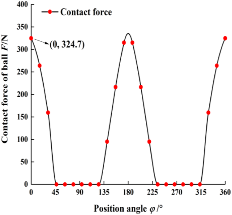
Contact force distribution of rolling elements.
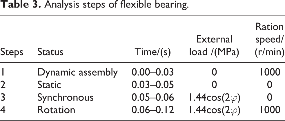
FEM model of CSF-40-80 flexible bearing is also established. The material properties of its components are presented in Table 2. Table 3 presents the steps of FEM analysis.
Components of flexible bearing.

Analysis steps of flexible bearing.
Contact stiffness is the most important parameter influencing the results. For surface–surface contact element model, contact stiffness is given by the normal stiffness factor (NSF). Assuming NSF equals to 1.6, the finite element results and the theoretical results of the maximum contact force are shown in Figure 4. The error between them is within 5%. Therefore, the FEM model and its settings are reliable.

Maximum contact force comparison.
Results and discussion
Equivalent stress at static state
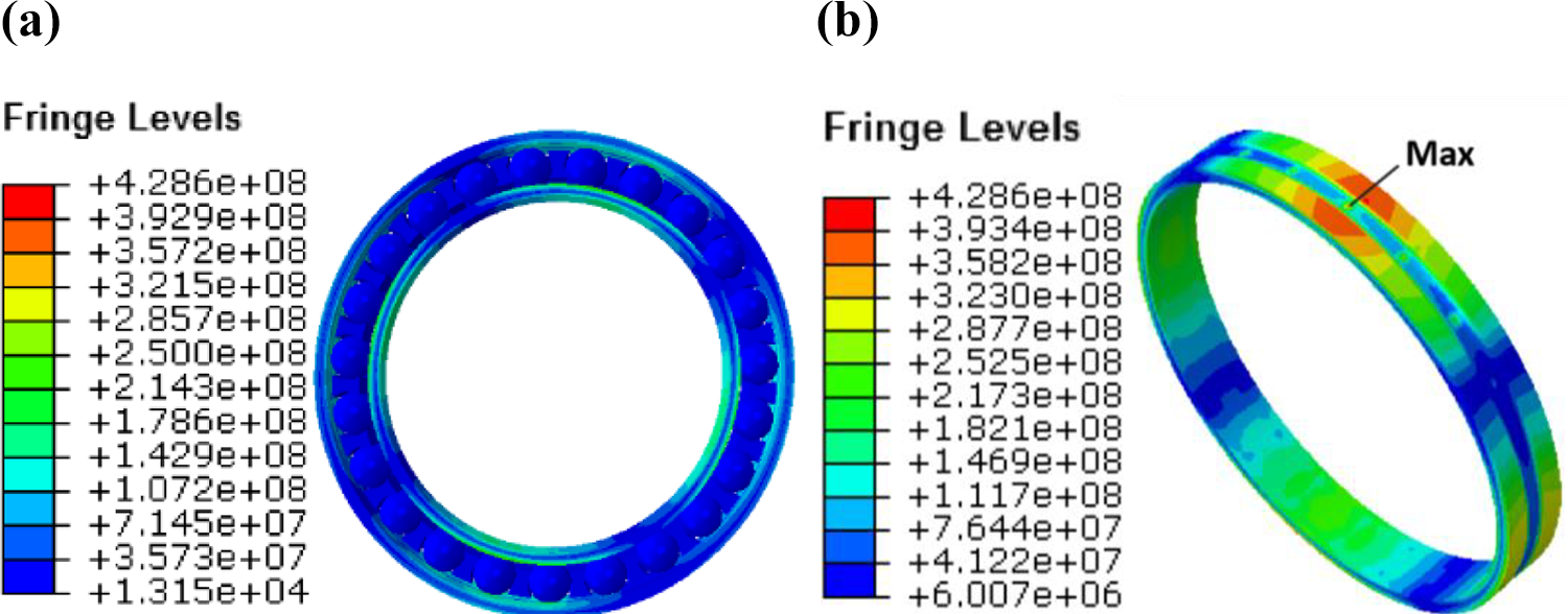
Figures 5 and 6 show the equivalent stress nephogram of flexible bearing with load and without load, respectively.

Equivalent stress nephogram without load: (a) flexible bearing and (b) inner ring.
Equivalent stress nephogram with load: (a) flexible bearing and (b) inner ring.
It can be seen from Figure 5 that the maximum equivalent stress of flexible bearing at static state without load is 336.8 MPa and it occurs at the position where the outer end surface of inner ring at the long axis is in contact with the rolling elements. Thus, it already has large equivalent stress before load. From Figure 6, we can see that the maximum equivalent stress is 428.6 Mpa when it is loaded, which is 27.3% higher than the former. It occurs at the contact point of the inner ring at the long axis and rolling elements. Therefore, it can be concluded that external load has a great influence on the equivalent stress of flexible bearing.
Dynamic analysis of flexible bearing on actual assembly
Analysis of outer ring
The motion of nodes at the long axis and the short axis of outer ring raceway is significant under the cosine cam. Therefore, the node N9 at the long axis and the node N23 at the short axis are selected. These nodes are shown in Figure 7.

Outer ring raceway of flexible bearing.
Deformation and velocity curves of N9 and N23 are shown in Figures 8 and 9.

Deformation curve of the outer ring raceway.

Velocity curve of the outer ring raceway(0–0.01 s).
It can be seen from Figure 8 that the deformation of the nodes N9 and N23 changes in the form of alternating crests and troughs, and the trend of these two nodes in different positions is identical. Crest will appear when the cam rotates for per one-fourth circle, which is consistent with the reality.
It can be seen from Figure 9 that the velocities of the nodes N9 and N23 changed in the form of alternating crests and troughs as well when the assembly of cam and inner ring is completed. The contact between rolling elements and outer ring raceway caused velocity fluctuations.
Analysis of rolling elements
Rolling elements at different positions are chosen in this study. CN34, DN34, and GN34 represent the chosen nodes where the rolling elements at the long axis, the short axis, and the transition region of the cam are in contact with the inner ring. The node N27 in inner ring raceway at the long axis is studied as well. These selected nodes are shown in Figure 10.

Chosen nodes distribution.
The displacements of CN34, GN34, and DN34 are shown in Figure 11, and the velocities of CN34, GN34, DN34, and N27 are shown in Figure 12.

Displacement of the rolling element versus time.

Velocity curve of each nodes of the flexible bearing.
Rolling elements rotate and revolve simultaneously and they are in contact with the inner and outer rings periodically when flexible bearing is working. It can be seen from Figure 11 that the displacements of CN34, GN34, and DN34 all increase alternately and the trend of each node is the same. Each crest indicates that the node is in contact with the outer ring and each trough indicates that the node is in contact with the inner ring. The alternating change represents the rotation motion of rolling elements while the increase of the displacement represents the revolving motion.
It can be seen from Figure 12 that the velocities of rolling elements change periodically when stable. Crests indicate that these nodes are in contact with the inner ring, while troughs indicate that these nodes are in contact with outer ring. Velocities of the nodes at the long axis and the transition region are approximately the same and slightly larger than the node at the short axis. The velocity of the node at the inner ring remains almost unchanged throughout the time.
Analysis of contact characteristics of flexible bearing on actual assembly
Analysis of outer ring
To reveal the stress change of outer ring, the equivalent stress nephogram of outer ring at 0.03 s is studied in Figure 13.

Equivalent stress nephogram of outer ring of flexible bearing.
Figure 13 shows that the equivalent stress of outer ring under cosine cam is first reduced and then increased throughout the long axis to the short axis. The maximum equivalent stress of outer ring occurs in the contact area of rolling element and the outer ring raceway at the long axis. The minimum equivalent stress occurs in the transition area of the outer ring. It can be concluded that the equivalent stress of the outer ring mainly occurs in the contact area of outer ring and rolling elements.
Figure 14 shows the stress distribution of N9 and N23. The stress of the outer ring raceway changes in the form of alternating crests and troughs at the long-axis region, while changes in an arc shape at the short-axis region are due to the contact between the rolling element and the outer ring. Stress mutation in N9 is earlier than N23 because of the periodic deformation of outer ring.

Equivalent stress curve of the long axis and short axis of the outer ring raceway.
Analysis of rolling elements
To reveal the stress of rolling elements, the equivalent stress nephogram of rolling elements at 0.03 s is studied in Figure 15. The equivalent stress of rolling elements mainly occurs near the long axis of the cam and the maximum equivalent stress occurs at the position where the rolling elements at the long-axis are in contact with the inner ring.

Equivalent stress nephogram of rolling element (t = 0.03 s).
The equivalent stress of the node CN34 is shown in Figure 16. It changes in the form of alternating crests and troughs when the rolling elements are near the long axis. Crests represent the alternate contact between rolling elements and the inner and outer rings, while troughs indicate that the rolling elements are not in contact with either the inner ring or the outer ring. The rolling elements enter the long-axis and the short-axis area of wave generator alternatively. The stress of rolling elements in the short axis of wave generator is 0 from 0.015 s to 0.04 s.

Equivalent stress curve of rolling element node CN34.
Three adjacent nodes N610, N612, and N614 of the rolling elements at the long axis are selected and shown in Figure 9. These nodes are not on the contact line of rolling elements and inner ring. From Figure 17, we can see that the stress of these nodes is related to the distance between the node and the vertex when the rolling element is near the long axis. The farther the node is from the vertex, the smaller its stress is. We can also see that the equivalent stress is basically 0 near the short axis.

Equivalent stress curves of different nodes on rolling elements.
Analysis of dynamic maximum equivalent stress
The acceleration of rolling elements is considered in dynamic state. From Figure 18, we can see that the dynamic maximum equivalent stress is 613.8 MPa, which is greater than in static state (428.6 MPa). It can be concluded that the fatigue strength at dynamic state is much lower than that at static state.

Maximum equivalent stress of flexible bearing versus time.
Conclusion
This article is mainly for the research on static and dynamic characteristics of flexible bearing. Some conclusions can be obtained as following:
In static state, the location of maximum equivalent stress on flexible bearing is related to whether it is loaded. When the bearing is not loaded, the maximum equivalent stress locates at the position where the outer end surface of inner ring is contacted with rolling elements and it locates at the contact point of the inner ring at the long axis and rolling element when the bearing is loaded. The actual number being loaded is 11 among the 23 rolling elements and it already has a large equivalent stress before load.
In dynamic state, deformations and velocities of nodes at the long axis and the short axis of outer ring change in the form of alternating crests and troughs. Rolling elements rotate and revolve simultaneously and they are in contact with the inner and outer rings periodically. Displacements of nodes at the contact area of rolling elements and inner ring raceway increase alternately. When the velocity of inner ring is stable, the velocities of rolling elements will change periodically.
The stress of the outer ring raceway changes in the form of alternating crests and troughs at the long-axis region, while it changes in an arc shape form at the short-axis region. The equivalent stress of rolling elements mainly occurs near the long axis of the cam. When rolling elements are near the long axis, the stress of these nodes where the rolling elements come into contact with the inner ring changes alternately and the stress of these nodes turns to be larger when the nodes are farther away from the vertex. On the contrary, the equivalent stress is basically 0 when the rolling elements are near the short axis. The fatigue strength of flexible bearing in dynamic state is lower than that of static state.
In this article, the mechanical properties of flexible bearings are analyzed by combining theoretical equations and finite elements model. Stress, deformation, and velocity are analyzed, which can guide the design and manufacture of flexible bearing.
Footnotes
Declaration of conflicting interests
The author(s) declared no potential conflicts of interest with respect to the research, authorship, and/or publication of this article.
Funding
The author(s) received no financial support for the research, authorship, and/or publication of this article.