
Abstract
A new type of parallel robot ROBO_003 is presented. Its mechanisms, kinematics, and virtual prototype technology are introduced. The research of degrees of freedom (DOF) is based on screw theory, a set of screw is separated as a branch, which named as constrain screw. The type of three DOF gained by counting constrain screw, the moving platform’s frame, and base platform’s frame is set, respectively, a complete kinematic research including closed-form solutions for direct kinematic problem. The 3-D model of ROBO_003 is established using SOLIDWORKS; position and orientation of motion platform can be gained using ADMAS, which is a type of virtual prototype technology. The resultant shows that the structure of ROBO_003 is reasonable, three DOF of motion platform can be operated in a reasonable range, the solutions to the direct kinematics are right, and robot ROBO_003 can be used in many industrial fields. The research of this article provides a basis for the practical application of parallel robotics ROBO_003.
Introduction
Since the advent of robots, its development prospects have become wider and wider, especially in many industrial fields, which greatly improve labor productivity and product quality, reduce production costs, reduce labor intensity, and improve labor conditions.
Most of the traditional robotic manipulators are made up of joints in series, which are base, waist, upper arm, lower arm, wrist, and end-effector, so they are called serial robots. This kind of robot has the advantages of wide working range and flexible movement. However, if degree of freedom (DOF) is more and the arm is longer, the stiffness is poor and the bearing capacity is low, so there is a phenomenon of error accumulation and amplification. Therefore, people need to study a new type of robot with high position accuracy, good stiffness, strong bearing capacity, and simple structure.
Parallel robot was first proposed by Stewart in 1965, it is called Stewart mechanism. 1 It consists of a moving platform, a fixed platform, and six parallel branches with two platforms. Each branch can be retracted. The two ends of the branch are connected with two platforms by spherical or Hooke hinges. When the length of each branch changes, the moving platform can obtain three DOFs (Figure 1).

Stewart platform.
In 1998, Professor Joachim in Germany designed a six-DOF parallel robot named triplanar (Figure 2). Triplanar is driven by three 2-DOF planar motors, ROBO_003 is the first model derived from triplanar since its birth (Figure 3). Its design conception comes from triplanar parallel robot and has its own obvious characteristics. 2
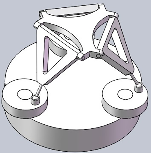
ROBO_003.

Triplanar.
Three 2-DOF planar motors of triplanar parallel robot are replaced by three rotating discs around fixed axes in ROBO_003, which is equivalent to restricting two-DOF free motion of three planar motors to one-DOF along fixed circumference.
ROBO_003 is a new type of parallel robot with three DOF, so it can also be called pure rotation parallel robot. With its unique structural advantages, ROBO_003 parallel mechanism has great application prospects in many fields, such as satellite antenna, radar, photovoltaic tracker, and so on. However, there is almost no systematic research on the mechanism of this kind of parallel robot, so its mathematical modeling and simulation is a very innovative and challenging work, as well as laying a solid theoretical foundation for its practical application, which is of great significance.
In this article, the screw method is used to analyze the number and form of the DOF of the mechanism, the virtual prototype technology of SOLIDWORKS and ADMAS is used to carry out kinematics modeling and simulation. The theoretical analysis and software simulation of ROBO_003 parallel robot are also an innovative work, which has important practical significance.
Analysis of DoF form
Screw theory
Among many mathematical methods for analyzing space mechanisms, screw is a very effective tool.
3
Firstly, it integrates six scalars, or two 3-D vectors, so that a screw can represent the direction and position of vectors at the same time, the velocity and angular velocity in rigid body motion, and the force and torque in rigid body mechanics. Therefore, screw with six scales is very useful for kinematics and dynamics analysis of spatial mechanisms. A vector in space is constrained on a line whose position is determined, the vector constrained by the line is called a line vector, which is expressed by a dual vector

where L, M, and N can be expressed as unit angular velocity; P, Q, and R can be expressed as unit line velocity. Corresponding to r,

The first three components represent the principal vector of the force screw, and the last three components represent the principal moment of the force screw. For two screws, if the following formula is satisfied, they are called reciprocal screws

According to the definition of reciprocal screw 5 , motion screw and force screw are a pair of reciprocal screw, and the sum of virtual power of external force system to stable rigid body is constant to zero at any time.
For an object connected to a fixed base by a pure series kinematic chain with n (n > 0) DOFs, its motion screw is the linear combination of the motion screw of all the motion pairs in the kinematic chain, which is expressed as follows
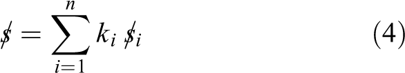
where

where J is motion screw system of the kinematic chain, According to reciprocal screw theory, the anti-screw
K can take any value. Therefore, the necessary and sufficient condition for the establishment of the above formula is

In formula (6)

Therefore, for any given pure series kinematic chain, the terminal constraint (anti-Screw) can be obtained by this formula, and the terminal constraint is known. The unconstrained motion is the DOF of the terminal.
DOF analysis of ROBO_003
Structural diagram of ROBO_003, as shown in Figure 4, one of branched chain


ROBO_003 structural diagram.

(a) ROBO_003 coordinate system and (b) the diagram of joint screw.
Spherical pairs in G
1 can be decomposed into three orthogonal rotating pairs.
9,10
And they intersect the center of rotation of the spherical pair, the coordinate of the center is


The direction and vector diameter of the axis of the rotating pair in Q 1 cannot be determined; so, its Screw can be set as follows:

The motion Screw of

It is expressed as the matrix:
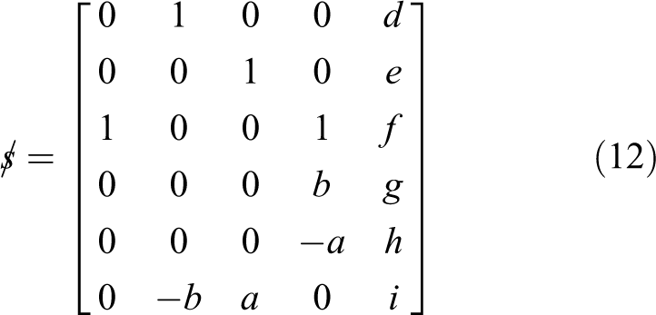
The rank of the matrix

According to the relation between the screw system, it is an anti-screw system, five equations are obtained as follows


By solving the above equations, we finally get a group of equation solutions

After calculation, we get the equation:

We can conclude from the resultant that the anti-screw of the motion screw is a line vector, the anti-screw has a meaning of force, and its direction vector is
Kinematics
Kinematics research only considers motion condition, not force condition. Position analysis is the most basic task of ROBO_003 kinematics analysis. Its essence is to solve the position relationship between input and output components of mechanism. It can be divided into two subproblems: the forward and inverse position solutions. 6,7 The former involves the known joint variables to solve the operation variables, and the latter involves the known operation variables to solve the joint variables. For parallel mechanisms, the process of calculating all possible motion parameters of the driving joint by giving the position and attitude parameters of the moving platform relative to the static platform is the inverse position solution; and the known driving joint is the inverse position solution. The forward position solution is the process of solving the position and posture of all possible moving platforms relative to the basic platforms.
Establishment of coordinate system
As shown in Figure 5(a) and (b), two equilateral triangles represent the base and the moving platform, respectively.
The input joint refers to the rotating pair between the base and the turntable, and the output joint refers to the rotating pair between the rod and the moving platform. The input and output refer to the input and output of motion. From the point of view of motion, the input joint is the driving joint and the output joint is the guiding joint, while the joint between the two, for example, the spherical hinges or pairs between the turntable and the rods are all transmission joints.
Quantitative analysis of motion requires setting motion parameters.
8
Each moving joint transmits the corresponding motion parameters, in parallel mechanism ROBO_003,
Position and orientation describing of moving platform
Position of moving platform
The position of the moving platform can be represented by the position vector of the center point C of the moving platform, the coordinate of point C, which relative to the base frame

Orientation of moving platform
For orientation of moving platform, we describe it by rotational transformation of the moving frame

The three angles ψ,θ,γ are called RPY angle, they are called roll, pitch, yaw angle, respectively, 9 which is the rotating angle of moving frame rotating around x-axis, y-axis, and z-axis.
Solutions for direct kinematic problem
Analytic method for close-form solutions
The mechanism parameters and input parameters of ROBO_003 parallel robot can be used to get the solution equation of moving frame, the closed solution is obtained, the mechanism parameters of ROBO_003 are provided in Table 1.
Parallel mechanism parameters.

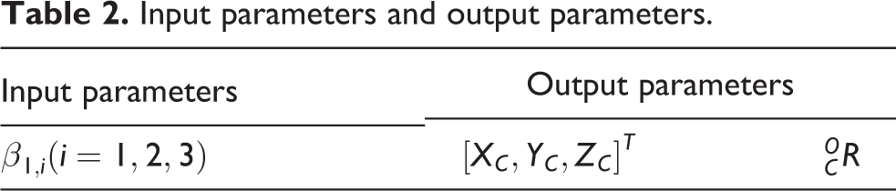
The kinematics of ROBO_003 studies the relationship between the input angle and the position and orientation of the moving platform. The input angle is the input parameter
Input parameters and output parameters.
The selection of reference frame will not affect the distance between two points. Obviously, the distance between the center of the spherical hinge Gi
and

The position vector of Gi
, that is, in frame

Setting the initial state of ROBO_003 parallel robot motion, point Gi
is on the xi
-axis of inertial frame

Setting

The position vector of


where


The position vector of Gi
in the frame

The position vector of theGi
point in the frame

Setting mi
is the distance from Gi
to

Therefore, the forward position analysis of ROBO_003 parallel mechanism can be reduced to the closed solution of the upper form.
Let
Substitute the upper form and get it:

When i = 1, 2, 3, the above formula is equivalent to the following equations:

Let

After simplification

To eliminate variables t 2, the first two equations are multiplied by t 2, two new equations are obtained. Consider the following two equations

The above equations are written in the form of matrices:

Only if the determinant of the fourth-order coefficient matrix is equal to 0, as following:

Expanded

Substitute

To eliminate the variables t 3,combine the above two formulas. Let the following six-order coefficient row number equals 0

The 16-degree polynomial equation of t 1 obtained by expanding and merging the same terms

where
Numerical examples
The value of structure parameter.

Calculating forward kinematics solution based on MATLAB, obtaining the three points’ coordinate of G 1, G 2, and G 3 respectively

The 16th order polynomial equation is as follows:

The eight real roots of t
1 are obtained by solving the above equation. The corresponding value of

Two sets of solutions of
Real number solutions of moving platform.

The corresponding four rotation matrices are obtained as follows


The above results are the forward kinematics solutions of parallel mechanisms of ROBO_003.
ADMAS simulation
Introduction of ADMAS
Automatic dynamic analysis of mechanical systems (ADAMAS) is a virtual prototype analysis software developed by American MDI Company. 23 The start-up interface of ADMAS is shown in Figure 7. The simulation steps of ADAMS are provided in Table 5.

The 3-D assembly model of ROBO_003.

Effect drawing of adding constraints and motions.
Simulation step of ADMAS.

Kinematics simulation of ROBO_003 based on ADMAS
Before simulation, CAD software Solidworks is used to build 3-D assembly drawing of ROBO_003, 24 as shown in Figure 6.
The assembly drawings are established in Solidworks, the parts of the 3-D drawings are saved in the form of suffix x_t. Import ADMAS and reassemble in ADMAS. 25 The assembled model establishes the simulation model in ADMAS interface according to the simulation steps in Table 5. The simulation time and steps are set up. The results are shown in Figure 7.
Simulation results
Centroid position change curve of moving platform
Results and discussion
In this article, a new type of parallel mechanism ROBO_003 was presented, it is DOF form, kinematics, and virtual prototype technology have been studied.
The DOF of parallel mechanism is based on screw theory by choosing the joint motion screw of three branches of parallel mechanism, the screw system of each joint is obtained, and the constraint screw of each branch chain is obtained by matrix calculation. The constraint screw of the screw system consisting of the constraint screw of each branch chain is the motion screw of the moving platform. From the calculation results of formulas (1) to (10), it can be concluded that the motion form of ROBO_003 parallel mechanism moving platform is three DOF rotation, that is, rotation around X, Y, and Z axes, respectively (Figures 8 and 9).

Centroid displacement changing curve (x-axis).

Centroid displacement changing curve (y-axis).
For the kinematics research, first, we established the frame of the moving platform and the base platform, then the frame of each joint was established, choosing the rotation angle of the moving platform frame relative to the base platform frame respectively, they are roll, pitch, yaw angle, the rotation matrix is obtained using homogeneous matrix transform to obtain position and orientation of moving platform relative to base platform, choosing key points on moving platform and base platform, respectively, and setting constraint equation. After eliminating, the 16-degree equation is simplified, the closed solution is obtained by analytic method, the 16-degree equation is solved by programming, and 8 pairs of positive position solutions are obtained. After choosing or rejecting, the final position and orientation of the moving platform relative to the base platform are obtained.
ADMAS virtual prototyping technology is a simulation technology for kinematics and dynamics of robots. It can correctly analyze the kinematics of ROBO_003 parallel mechanism. According to theoretical calculation and ADMAS virtual prototyping technology, Figures 10 to 12 are displacement curves of the center of mass of moving platform in three directions of X, Y, and Z axes. Figures 13 to 15 are velocity curves of moving platform centroid in three directions of X, Y, and Z axes. Figures 14 and 15 are angular velocity and acceleration curves of moving platform relative to base platform orientation. The results show that the simulation results coincide with the actual theoretical calculation.

Centroid displacement changing curve (z-axis).

Centroid velocity changing curve (x-axis).

Centroid velocity changing curve (y-axis).

Centroid velocity changing curve (z-axis).

Angular velocity changing curve of moving platform.

Angular acceleration changing curve of moving platform.
Conclusions
In this article, the screw theory is used to study the DOF form of ROBO_003 parallel mechanism, the closed solution of forward kinematics is studied by analytical method, and the forward kinematics solution is obtained by simulation with ADMAS software. The results accord with the theoretical calculation value. The research results provide a theoretical basis for the practical application of ROBO_003 parallel mechanism.
For complex parallel mechanisms, the screw analysis method proposed in this article can easily solve the analysis of the DOF form of parallel mechanisms. It is concluded that the DOF form of ROBO_003 parallel mechanisms is three DOF rotation. The ADMAS virtual prototype can easily obtain the forward kinematics solution and the process of pose change.
The research of parallel mechanism has broad prospects. In the future, there will be more mathematical theories applied in mechanics, kinematics, and dynamics. ROBO_003 parallel mechanism can be applied to various industrial aerospace and aerospace fields, and its application prospect and values are very great.
Footnotes
Declaration of conflicting interests
The author(s) declared no potential conflicts of interest with respect to the research, authorship, and/or publi-cation of this article.
Funding
The author(s) disclosed following financial support for the research, authorship, and/or publication of this article: This work was supported by the College Natural Science Foundation of Jiangsu Province (no. 17KJB460003), National Key Research Planning Project(No.2018YFC0309100), National Natural Science Foundation of China (no. 51375230), and Key Construction Subject Project of Jiangsu Province (no. (2016)9)